EP0602439A2 - Photographic material advancement adaptation unit for plant for continuous development - Google Patents
Photographic material advancement adaptation unit for plant for continuous development Download PDFInfo
- Publication number
- EP0602439A2 EP0602439A2 EP93119164A EP93119164A EP0602439A2 EP 0602439 A2 EP0602439 A2 EP 0602439A2 EP 93119164 A EP93119164 A EP 93119164A EP 93119164 A EP93119164 A EP 93119164A EP 0602439 A2 EP0602439 A2 EP 0602439A2
- Authority
- EP
- European Patent Office
- Prior art keywords
- photographic material
- units
- adaptation
- operative
- unit
- Prior art date
- Legal status (The legal status is an assumption and is not a legal conclusion. Google has not performed a legal analysis and makes no representation as to the accuracy of the status listed.)
- Granted
Links
Images


Classifications
-
- G—PHYSICS
- G03—PHOTOGRAPHY; CINEMATOGRAPHY; ANALOGOUS TECHNIQUES USING WAVES OTHER THAN OPTICAL WAVES; ELECTROGRAPHY; HOLOGRAPHY
- G03D—APPARATUS FOR PROCESSING EXPOSED PHOTOGRAPHIC MATERIALS; ACCESSORIES THEREFOR
- G03D13/00—Processing apparatus or accessories therefor, not covered by groups G11B3/00 - G11B11/00
- G03D13/007—Processing control, e.g. test strip, timing devices
-
- G—PHYSICS
- G03—PHOTOGRAPHY; CINEMATOGRAPHY; ANALOGOUS TECHNIQUES USING WAVES OTHER THAN OPTICAL WAVES; ELECTROGRAPHY; HOLOGRAPHY
- G03D—APPARATUS FOR PROCESSING EXPOSED PHOTOGRAPHIC MATERIALS; ACCESSORIES THEREFOR
- G03D13/00—Processing apparatus or accessories therefor, not covered by groups G11B3/00 - G11B11/00
- G03D13/003—Film feed or extraction in development apparatus
Landscapes
- Physics & Mathematics (AREA)
- General Physics & Mathematics (AREA)
- Photographic Processing Devices Using Wet Methods (AREA)
- Projection-Type Copiers In General (AREA)
- Advancing Webs (AREA)
- Paper (AREA)
- Compositions Of Macromolecular Compounds (AREA)
- Cultivation Of Plants (AREA)
- Agricultural Chemicals And Associated Chemicals (AREA)
Abstract
Description
- The invention refers to operative units for a plant for continuous development of photographic material (film or paper), to adapt the advancement speed of such photographic material among the different component elements of such developing plant.
- From the U.S. patent n. 4,782,354 it is known a plant for the automatic and continuous photographic development of photographic material like film and paper, comprising substantially a plurality of different per se known operative units, as i.e. splicers, photographic film developing machines, labelling machines, printing machines, which can be combined to each other at variable sequences depending on the needs of the different customers, to achieve the automatic and continuous development of such photographic material.
- The plant referred to, in particular, is provided with one or more photographic material storage units interposed between the one and the other one of the above mentioned operative units and constituted by a set of rotating rollers applied on the upper side of the associated units, having stationary rotation axles, as well as a set of rotating rollers applied on the lower side of such unit, having rotation axles which are either stationary or displaceable with respect to the upper roller axles, so that the photographic material is wound around the respective upper and lower rollers and a continuos advancement thereof from the one operative unit to the other one during the operation of the plant referred to be caused. Therefore, these storage units besides providing the photographic material advancement, allow also the immediate storage thereof at variable rate onto such upper and lower rollers, thereby compensating the unavoidable changes of the advancement speeds of the photographic material leaving the directly preceding operative units, in order that the photographic material being leaving such storage units may arrive with the pre-established advancement speeds at the subsequent plant operative units.
- Finally, all the operative and storage units of the so formed plant are connected to one or more data processors, which control the carrying out of the relevant pre-established operative sequences thereof, to provide for the advancement of the photographic material through all the units, so as to obtain the development and printing of the same material.
- From the U.S. patent n. 4,930,672 it is known a photographic material storage unit, which is used on the above mentioned photographic material developing and printing plant, which unit is substantially identical to those of the same plant and is provided with further sets of upper and lower rotating rollers, these latter having rotation axles displaceable with respect of the axles of the upper rollers, said rollers being situated at the inlet and outlet side of each storage unit to permit the removable connection thereof with the adjacent plant operative units, for the same objects previously specified. However, the so formed plant has different inconveniences. First of all, each storage unit is obtained with considerable overall dimensions and is always constituted by a compensation mechanism of the photographic material advancement speeds (comprising the upper and lower rotating rollers) which is incorporated on an actual photographic material storage warehouse, so that after all it is complicate on its construction and requires the availability of considerable spaces for the installation thereof together with the different plant operative units.
- Besides, such storage unit needs always a determinate response time, even if of limited duration, for the compensation of the different photographic material advancement speeds between the outlet side of the one operative unit disposed directly upstream and downstream the same storage unit, owing to the unavoidable inertia of the compensation mechanism forming said storage unit, which circumstance in the case in which the storage unit is relatively spaced from an associated operative unit adjacent thereto, might involve undesired changes of the sliding path of the photographic material between such adjacent units, with the hazard of distortions and/or eventual breakings of such material. Finally, all the operative and storage units of the plant referred to are controlled in a manner dependent from each other by the process computer, so that an eventual operative failure or defect of any one of such units may involve undesired operation stoppings of the entire plant.
- The present invention has the object to overcome the above described inconveniences and limits, by the use of particular adaptation units which are installed between the one operative unit and the other one, so as to permit a correct advancement of the photographic material through the plant operative units, by making also flexible and very reliable the operation thereof, with the possibility to combine also in a different way the same operative units thereamong, depending on the needs of the single customers.
- These adaptation units are made with the constructive features substantially described, with particular reference to the attached patent claims.
- The invention will appear more understandable from the following description, given solely by way of a not limiting example, and with reference to the accompanying drawings, wherein :
- Fig. 1 shows schematically a perspective view of a possible embodiment of a photographic material developing plant, incorporating the present adaptation units ;
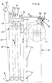
- Figs. 2 and 3 show schematically, in a lateral cutaway view, the two different adaptation units according to the invention ;
- Figs. 4 and 5 show an enlarged item of the adaptation unit of Fig. 3, displaced in two different operative positions.
- With reference to the Fig. 1, it is shown a possible embodiment of a plant for automatic continuous development of photographic material (paper and film), of the type with continuous strip, in the present case for the photographic paper, comprising substantially a conventional developing machine 6, a first warehouse - storage means 7, a quality checking table 8, a second warehouse - storage means 9, a
cutting equipment 10 formed i. e. by a common cutter or the like, and adisplay unit 11, as well as comprising the adaptation units according to the invention, namely afirst adaptation unit 12 placed between theoutlet side 13 of the developing machine 6 and theinlet side 14 of the first warehouse - storage means 7, and asecond adaptation unit 15 placed between theoutlet side 16 of the second warehouse - storage means 9 and theinlet side 17 of thecutting equipment 10 and acting as feeder for this latter. - As usual, the developing machine 6 (in this case, of the photographic paper) is provided with the
different treatment tanks 18 containing the different chemical baths required for developing the photographic material introduced in the same machine, which baths for convenience aren't cited as they are per se known, as well as is provided with photographicmaterial drying units 19, also of per se known type, for the complete drying of the developed photographic material, and an end collecting zone 20 in which the developed and dried material is adequately conveyed, to be subsequently picked up and passed through the following plant operative units. - In turn, the warehouse - storage means 7 and 9 are also provided, as usual, with a plurality of upper and lower rotating rollers (not shown in the Figure), which can be driven in rotation by at least an associated electric motor with speed adjustable in a per se known manner (also not shown), rollers around which the photographic material is wound to provide for both the transport on the advancement direction A thereof through all the plant operative units and the temporary storage thereof, in such a way as to be able to take up an exceeding amount of photographic material coming from the operative unit situated directly upstream the associated warehouse - storage means, when the unit situated directly downstream the warehouse - storage means referred to is stopped or operates with limited advancement speed of the photographic material, for operative requirements of said unit situated downstream, and in such a way as to be able to supply said unit situated downstream with photographic material, when this latter unit operates with considerable accelerations. Moreover, such warehouse - storage means 7 and 9 are advantageously paired with associated sets of guiding
rollers - In the present case, the sets of guiding
rollers inlet side 23 of the quality checking table 8, between this latter and theoutlet side 24 of the first warehouse - storage means, and at theoutlet side 25 of said checking table, between this and theinlet side 26 of the second warehouse - storage means 9. - As usual, the quality checking table 8 is provided for the inspection of the quality of the developed printings of the photosensitive material and the image printed onto the photographic paper, while in turn the
cutting equipment 10 is provided for automatically cutting at the required size the photographic material (in this case, the photographic paper), and thedisplay unit 11 permits to display on real time the different plant operative parameters and operative state, and the input of the operative parameters needed to insure the operation of the same plant. - Finally, the first and
second adaptation units - These adaptation units, which will be described in detail hereinafter, are substantially provided with at least an associated control means shaped as a microprocessor (not shown), connected to the entire electric wiring harness of the whole plant, which interconnects all the operative units and adaptation units of the same plant, said microprocessor being arranged to control by means of an information data exchange both the correct operation of the respective adaptation unit, by signalling immediately any anomalous operative condition thereof ((failure, stop etc..), and to control the operative state of the operative units situated directly upstream and downstream the adaptation unit referred to, so as to enable or disenable the operation of this latter and the operative units adjacent thereto, depending on such operative state of said operative units.
- Likewise, also the remaining plant operative units are provided with at least a respective control means of the same type, adapted to control the operation thereof in the same manners, which is also connected to the electric wiring harness of such plant together with the associated control means of the other operative and adaptation units.
- Furthermore, the control means of all the operative and adaptation units, besides performing the control functions on the respective pertaining unit and the adjacent ones, contain the informations of all the operative sequences that the remaining plant operative and adaptation units must perform. This means that each operative and adaptation unit is autonomous with respect to the other ones and, in the case in which it should operate in an anomalous way (owing to failures, stops etc...), so disenabling in case one or more units adjacent thereto, the remaining plant units will continue to operate in an independent way, thereby providing always the advancement of the photographic material through the plant, up to the stop thereof is caused by the units adjacent thereto, which in turn are influenced by such disenabled units. Therefore, it appears evident that, thanks to the fact that each microprocessor of an unit contains the informations of all the plant operative sequences, it can be connected to those of the remaining plant units through a wiring harness prearranged for a smaller data information exchange, since in this case there are eliminated such informations of the total plant operative sequences, which wiring harness therefore is considerably underdimensioned and more simple with respect to those employed for the plants of this kind previously existing.
- Moreover, this wiring harness may be made with smaller overall dimensions and lends itself to be connected in a simple, quick and removable way among the different plant units, which therefore may be combined to each other with different and variable numbers and combinations, depending on the customer needs, by making also very flexible and reliable the so constructed plant.
- In this way, there may be obtained also plants with units different than those described by way of example, by providing always at least two
adaptation units - By examining now the Figs. 2 and 3, there are shown schematically the two
adaptation units first adaptation unit 12 referred to, which in the case of the present plant is disposed between theoutlet side 13 of the photographic material developing machine 6 (in the present case, of the photographic paper), and theinlet side 14 of the first warehouse - storage means 7, situated on the upper side of such warehouse - storage means, so as the photographic material be transported in its advancement direction A from thefirst adaptation unit 12, in which it is introduced as it will be described later, toward such warehouse - storage means 7 by means of suitable conveyor devices (not shown in the Figure) of per se known type, interposed between said adaptation unit and said warehouse - storage means. - As evident from this Figure, the
adaptation unit 12 comprises substantially a set of idlerotating rollers 27 parallel to each other and having horizontal axle of rotation, applied on the upper side of a box-like envelope 28, transversally thereto, whose rotation axles are stationary, as well as comprises another set of idlerotating rollers 29 parallel to each other and having horizontal axle of rotation, applied on the lower side of such box-like envelope, transversally thereto, whose rotation axles are movable vertically with respect to the correspondent axles of theupper rollers 27, eiher in the one or other one of the two directions B or C, from an upper position of end of stroke to a lower one in which said lower rollers are respectively raised and brought closer to theupper rollers 27, and lowered and moved away of the greatest distance from such upper rollers. - Besides, this adaptation unit comprises additional idle rotating rollers having horizontal axles of rotation, disposed on the upper side of the same unit, above the
upper rollers 27, which in the present example are formed by tworotating rollers inlet side zone 32 of the adaptation unit, at a position opposite and brought closer with respect to theoutlet side 13 of the developing machine 6 (not shown in the Fig. 2), as well as a rotatingroller 33 spaced rectilinearly from the preceding pair ofrollers like envelope 28, and a rotatingroller 34 aligned rectilinearly and perpendicularly with respect to the correspondentlower rollers 29. - A powered rotating roller 35 which can be driven in rotation by an own
electric motor 36 having steady or variable torque, through a belt driving 37 or the like, is additionally situated between the idle rotatingrollers idle rollers pressing roller 38 co-operating with the powered roller 35 to insure always a correct advancament in the direction A thereof, said photographic material being afterwards wound like a coil among the differentupper rollers 27 andlower ones 29, by leaving the last lower roller with aninclined portion 39 thereof directed upward, which is suitably guided by anidle roller 40 applied externally the adaptation unit, thus being able to arrive at theupper inlet side 14 of the first warehouse - storage means 7. The adaptation unit referred to, in addition, comprises a dispensingroller 41 having large diameter, situated at a position below to and coincident with the photographic materialinlet side zone 32 and contains a driving band (leader) wound thereon, adapted to entrain the photographic material through all the sliding path thereof in the adaptation unit and the following plant operative units, which driving band is guided toward saidinlet side zone 32 by means of adequateidle guide rollers roller 41 and said pair ofidle rollers like envelope 28, at such positions as to be able to sense steadily the coil shaped sliding path of the photographic material among the sets ofupper rollers 27 andlower ones 29. Advantageously, as in case of the present embodiment, thesensors 44 are arranged reciprocally aligned and equally spaced vertically, parallelly approached to the photographic material, so that to be able to sense the presence of the photographic material wound around thelower rollers 29, depending on the vertical shifting of the same rollers, from the one to the other one of the upper and lower positions of end of stroke, by passing through different intermediate positions. The object of this sensing is to determine instantaneously and automatically the quantity of photographic material provided or not provided in the above coil shaped path, which material is collected therein or dispensed therefrom in a variable way depending on the different operative conditions of the units situated directly upstream and downstream the present adaptation unit, thereby compensating the different photographic material advancement speeds in the various plant operative units, therefore providing for a correct advancement and tensioning of said photographic material through all the above operative units. To this purpose, the microprocessor of the adaptation unit is set in advance in such a way as to receive coded informations of the presence or not presence of the photographic material in correspondence of any one of thesensors 44, and to convert instantaneously such informations into quantities of photographic material actually provided within the coil shaped path, so as to be able to interact adequately with the operative unit situated directly downstream the adaptation unit referred to, in order to compensate effectively the photographic material advancement speeds among these units. - In particular, in the considered case when the microprocessor senses the presence or not presence of the photographic material, which marks the temporary containing capacity of the same material into the warehouse determined by such coil shaped path, it provides to process a coded response information corresponding to such temporary containing state, which information is transmitted to the microprocessor of the first warehouse - storage means 7, which consequently provides to control the driving motor for the rotating rollers of such operative unit, and in case it is transmitted, in the case of anomalous operation thereof, also to the
electric motor 36 for operating the powered roller 35 of the adaptation unit referred to, so as to be able to influence suitably either the one or the other one of these motors, or both, in order to share properly the photographic material among thevarious units - In this way, the microprocessor senses steadily the presence of the photographic material along the entire coil shaped path thereof and, depending on the respectively sensed quantity of photographic material, it provides to control adequately the rotation of the driving motor for the rotating rollers of the warehouse - storage means 7, in a way to accelerate such rotation for a determinate time when a considerable collection of photographic material within said coil shaped path is produced, thereby transferring it rapidly into the warehouse - storage means 7, and to keep steady or to stop such rotation respectively in cases in which the photographic material has been collected at normal quantities or is fully absent within said coil shaped path.
- Moreover, under these operative conditions the microprocessor keeps the
motor 36 of the adaptation unit referred to steadily on, which is driven in rotation at the same advancement speed of the photographic material being coming from the preceding operative unit (in this case, the developing machine 6). Vice versa, should thelower rollers 29 be raised or lowered in correspondence of the associated upper o lower sensors of end of stroke under the eventual anomalous operation conditions, so such microprocessor would provide to signal such conditions by stopping in case the rotation of theabove motor 36. - The just described adaptation unit is also provided with suitable safety systems, to prevent the photographic material damaging and/or breakage in case of failures or operative faults of the same unit. Such safety systems, which are generally formed by adequate per se known sensors (not shown) housed within the coil shaped path of the photographic material and connected operatively to said microprocessor, provide to signal continuously the adaptation unit operative condition to the microprocessor, in order that it may influence such operative condition in case of anomalous operations thereof, while signalling at the same time these anomalous operations. In the case referred to, in particular, the safety systems provide to produce through the microprocessor the stopping of the
electric motor 36 and the adaptation unit off, when eventual breakages or defective operations of the same unit or the operative unit situated directly upstream or downstream thereto do exist, and these anomalous conditions are adequately signalled on theplant display unit 11 by the microprocessor, so as to be able to repair the adaptation unit by restoring the correct operation thereof. By examining now the Fig. 3, it is represented thesecond adaptation unit 15 according to the invention, which in case of the present plant is arranged between theoutlet side 16 of the second warehouse - storage means 9 and theinlet side 17 of thecutting equipment 10 and is also provided with an own control microprocessor (not shown). - As evident from this Figure, the
adaptation unit 15 comprises substantially, as the preceding unit, a set of idlerotating rollers 45 parallel to each other and having horizontal axle of rotation, applied on a horizontal fixedarm 46 disposed on the upper side of a box-like envelope 47, transversally thereto, and supported by avertical column 48 joined to the the box-like envelope 47 and resting on the floor, as well as comprises another set of idlerotating rollers 49 parallel to each other and having horizontal axle of rotation, applied on ahorizontal arm 50 supported by thevertical column 48 and disposed on the lower side of the box-like envelope 47, transversally thereto, which arm is movable vertically with respect to theupper arm 46 either in the one or other one of the two directions D or E, from an upper to a lower position of end of stroke in which said lower rollers are respectively raised and brought closer to theupper rollers 45, and lowered and moved away of the greatest distance from such upper rollers. In addition, this adaptation unit comprises further idle rotating rollers having horizontal axles of rotation, disposed on the upper side of the same unit, above theupper rollers 45, which in the present example are formed by a first rotatingroller 51 situated on theinlet side zone 52 of the adaptation unit, at a position suitable to receive the photographic material arriving orthogonally from theupper outlet side 16 of the second warehouse - storage means 9, by a second rotatingroller 53 situated at a position aligned vertically above thelower roller 49 more shifted toward the end of the associatedsupport arm 50 with respect to the remaininglower rollers 49, and by a third rotatingroller 54 interposed between the two precedingidle rollers upper rollers 45 and thelower ones 49 and an upper powered rotatingroller 56, co-operating with a movablepressing roller 57 placed side by side to the previousupper rollers 45 and supported by thesame arm 46, by leaving such powered roller with aninclined portion 58 thereof directed downward, and then, after having formed a circular loop 59, directed upward with a furtherinclined portion 60 thereof, which finally is bent almost orthogonally in the horizontal direction, with a suitable radius, by passing through two idle rotatingrollers mechanical clutch device 63 of per se known type, so as to arrive at theinlet side 17 of thecutting equipment 10. - In this way, this adaptation unit performs the same compensating functions for the different photographic material advancement speeds in the various plant operative units, with the same manners described for the preceding
adaptation unit 12. Furthermore, the adaptation unit referred to may be provided optionally with anotherelectric motor 64 too, adapted to rotate by means ofdriving belt 65 or the like the one of the idle rollers, i.e. theroller 54, with the aid of a movablepressing roller 55 for tensioning the photographic material, in order to help the photographic material advancement through the coil shaped path of the same adaptation unit, when the pull exerted by the weight of thelower rollers 49 is not enough to permit a correct advancement of this photographic material. - In turn, the
mechanical clutch device 63 serves to insure always a correct automatic tensioning for the photographic material, for adapting it to the changes of tension being produced in the subsequent operative unit (in this case, the cutting equipment 10). Advantageously, in case in which the present adaptation unit must be positioned upstream any operative unit which must operate in a continuous way, it is appropriate to provide also acutting device 66 at the outlet side of the same unit, by arranging this device i.e. on the upper side of the photographic materialinclined portion 58, as evident from Fig. 3, or also at different positions, adequate for this aim. Preferably, also this cutting device is of mechanical type to permit to cut the material at conditions of emergency and electric supply lack. - In the Figs. 4 and 5 it is schematically shown the
cutting device 66 moved into two different operative positions thereof, respectively at the rest position in which it does't cut the photographic material and at the operating position in which it cuts the photographic material. - From such Figures, it is noted that the
cutting device 66 is substantially constituted by a horizontalrectilinear arm 67, fixed at the one end thereof to thevertical column 48 of theadaptation unit 15 and provided with suitablevertical guide elements 68 for passing the photographic material being leaving said adaptation unit and directed toward the subsequent plant operative unit. - Such fixed
arm 67 is also associated to amovable arm 69 slidable rectilinearly and horizontally with a limited stroke with respect thereto, which movable arm is provided with acutting element 70 in which athrough hole 71 is provided, to allow the photographic material to pass therethrough, as well as arack portion 72 at its free end, adapted to engage acorrespondent sector gear 73 connected on an articulated manner to the end of a furtherrectilinear arm 74. - This
rectilinear arm 74 is supported by theprevious arm 67 by means of anadditional arm 75, in which it is articulated together with thesector gear 73, and is also connected resiliently by means of at least acompression spring 76 which tends to maintain thearms movable arm 69 is moved by thesector gear 73 and therack portion 72 in such a way as thecutting element 70 be arranged with its throughhole 71 aligned with thevertical guide elements 68. - Then, under this operative condition the photographic material may slide freely through said
guide elements 68 and said throughhole 71 and insn't affected by the cutting blade of thecutting elements 70. - In turn, the
rectilinear arm 74 is provided at its free end with an idle rotatingroller 77 adapted to permit the guide and sliding of the photographic material, in case in which a scarcity of photographic material within the coil shaped path of the adaptation unit referred to does exist. - Under these conditions of presence of a scarce quantity of photographic material within said adaptation unit, then, such material arranges itself against the
rotating roller 77 of therectilinear arm 74, therefore by shifting this latter onto its operating position shown in Fig. 5, against the action of thespring 76, in which position saidrectilinear arm 74 is rotated at a certain amount with respect to the fixedarm 67. This rotation of therectilinear arm 74 produces a consequent limited horizontal sliding of thecutting element 70, thanks to the engagement between thesector gear 73 and therack portion 72, so as the photographic material is cut by the cutting blade of said cutting element. Moreover, the adaptation unit referred to comprises a windingroller 78 of large diameter situated at a position above and coincident with respect to the photographic materialoutlet side zone 79, to permit the driving band (leader) arriving from the preceding dispensingroller 41 of the other adaptation unit and passing through all the plant operative units, for entraining the photographic material therewith, to be wound onto said roller, said driving band being guided toward the same cited photographic material sliding path by suitableidle guiding rollers roller 78 and saidoutlet side zone 79. Finally, as for theprevious adaptation unit 12, also the present adaptation unit comprises a plurality ofsensors 82 of the same type and for the same control functions as well as positioned in the same manner with respect to thecorrespondent sensors 44 of theadaptation unit 12, so that it is deemed appropriate to omit these features already known from the preceding description. - In addition, this
adaptation unit 15 comprises a plurality offurther sensors 83 of the same type, positioned along thevertical column 48 in such a way as to be able to sense constantly the sliding path of thephotographic material portions sensors 83 are arranged reciprocally aligned and equally spaced vertically, parallelly approached to the photographic material, so as to be able to sense the presence of photographic material being passing through the above sliding path, for the same objects previously described. Therefore, on thisadaptation unit 15 the microprocessor thereof is predisposed to receive coded informations of the presence of photographic material, not only in correspondence of therespective sensors 82, in order to convert them into correspondent quantities of photographic material with the same preceding manners, but also in correspondence of therespective sensors 83, in order to be able also in this case to obtain with the same criteria the quantity of photographic material being collected or not collected within the above sliding path of the same material, so that such microprocessor may influence thepowered roller 56 and the eventualelectric motor 64 of the adaptation unit referred to, as well as the control motor (not shown) of the former operative unit (in this case, the warehouse - storage means 9), with the same operative criteria previously described to get always the same purposes, namely by keeping thepowered roller 56 and the eventualelectric motor 64 on and by operating the motor of the rotating rollers of the warehouse -storage means 9. Therefore, also in this case the sensors may sense the presence or not presence of the material up to the one upper and lower position of end of stroke, corresponding to anomalous operative conditions for which a relevant signalling is provided to thedisplay unit 11, with eventual stop of the powered roller 56 (in case of sensing of the photographic material within the coil shaped path), or suitable change of the speed of said powered roller (in case of sensing in thephotographic material portions 58, 59 and 60). Of course, theadaptation unit 15 too is provided with the same safety systems previously described, which are housed and operating with the same criteria thereof. - Therefore, on a plant for continuous development of photographic material comprising adaptation units of this kind, the photographic material arriving from a plant operative unit (in this case, the developing machine 6) is firstly joined adequately to a driving band, previously introduced along the sliding path of the photographic material through all the plant adaptation units and operative units, by unwinding such driving band from the dispensing
roller 41 of theadaptation unit 12 and winding it around the windingroller 78 of theadaptation unit 15. - In this way, also the photographic material is inserted along all the sliding path thereof, for performing the foreseen treatment operations, while in turn the driving band is fully wound onto such winding
roller 78 which is then removed from its seat and assembled again onto thefirst adaptation unit 12, instead of the previous emptiedroller 41 which is now assembled onto the second adaptation unit, for performing the function of winding roller, then such driving band being joined to the end of the last photographic material to be treated within the plant, for a subsequent winding thereof around the winding roller so as to repeat the described cycle. The so obtained adaptation units permit therefore to combine in a flexible manner varied operative units to each other on a photographic material developing plant, which units thus can be arranged more rationally also within restricted spaces of installation, also permitting the continuous and quick compensation of the different advancement speeds of such photographic material through the plant, without dangers of distortions and/or breakages of the same material. - Moreover, thanks to the fact to include independent control means like the microprocessors, the adaptations units and the remaining operative units of the plant referred to may operate in a manner independent to each other, thereby avoiding to stop the entire plant in case of any eventual operative failure or fault of one or more of the same units.
Claims (5)
- Photographic material advancement adaption unit for plant for continuous development of photographic material, comprising a plurality of operative units of per se known type (developing machine 6; warehouse - storage means 7, 9; quality checking table 8; cutting equipment 10 etc...), which can be combined to each other on different manners, through which the photographic material is being passed for the treatment thereof, as well as comprising at least a display unit (11) of per se known type for controlling and inspecting the operation of said operative units (6; 7, 9; 8, 10) and said adaptation units (12, 15), said operative units (6; 7, 9; 8, 10) and said adaptation units 12, 15) being provided with powered means (35; 56, 64) to provide for the photographic material advancement and control means (microprocessor) which are independent to each other, predisposed to control the operation of the respective units in accordance with pre-established operative cycles and depending on the operative state of the other operative units and adaptation units directly adjacent thereto, said adaptation units (12, 15) comprising guide means (30, 31, 33, 35, 34; 51, 54, 53) shaped as rotating rollers for passing the photographic material and at least a driving band (leader) for entraining it therethrough, and temporary collecting means (27, 29; 45, 49) shaped as stationary upper rollers and movable lower rollers, for winding the photographic material thereon, adapted to compensate the changes of the photographic material advancement speed through the different plant units, by means of a succession of storages and dispensing of such photographic material between the one and the other one unit, characterized by at least a first and a second adaptation units (12, 15), autonomous and separated as well as interposable removably between two operative units which are consecutive from each other (6, 7; 9, 10), said first and second adaptation units (12, 15) being provided with sensor means (44; 82, 83) adapted to sense as coded informations the quantity of photographic material which is provided from time to time within said temporary collecting means (27, 29; 45, 49), said sensor means (44; 82, 83) being controlled by said control means in such a way as to influence said powered means of the plant units respectively adjacent thereto, and in case also said powered means (35; 56, 64) of the adaptation units (12, 15), in a way to change or stop the rotation of the same powered means depending on the photographic material being provided within the respective adaptation unit.
- Adaptation unit according to claim 1, characterized in that said sensor means (44; 82, 83) comprise a plurality of electronic, electric, electromechanical or similar sensors of per se known type, connected operatively to said control means and adapted to sense or not sense the presence of the photographic material along its sliding path, up to an upper and a lower position of end of stroke thereof, which is signalled through said display unit (11), and corresponding to anomalous operative conditions of said first and second adaptation units (12, 15).
- Adaptation unit according to claim 2, characterized in that said first and second adaptation units (12, 15) comprise respectively at least a dispensing roller (41) and a winding roller (78) for the driving band, arranged removably in correspondence of the photographic material sliding path, to allow said driving band to pass from the one to the other one of said dispensing roller (41) and winding roller (78).
- Adaptation unit according to claim 3, characterized in that said second adaptation unit (15) comprises clutch means (63) of per se known type, to keep almost steady the tension of the photographic material being leaving the same unit, before to arrive on the subsequent operative unit, as well as eventual cutting means (66) disposed between the unit outlet side (79) and said clutch means (63), to cut at intervals the photographic material.
- Adaptation unit according to claim 4, characterized in that said cutting means (66) comprise a first rectilinear arm (67) fixed to said second adaptation unit (15), a second movable arm (69) co-operating with said first fixed arm (67) and provided with at least a cutting element (70) adapted to cut the photographic material, as well as comprise a third rectilinear arm (74) provided at an end thereof with at least an idle rotating roller (77) for the photographic material sliding and guiding, in case of scarcity of photographic material within said second adaptation unit (15), said third arm (74) being articulated at its other end with a fourth arm (75) fixed to said first arm (67), and being joined to said fourth arm (75) by spring means (76) adapted to keep said arms (74, 75) pushed the one toward the other one, as well as being provided at its other end with driving means (73) engaging correspondent driving means (72) provided on said second movable arm (69), said third arm (74) being adapted to shift said second movable arm (69) together with said cutting element (70), by means of said driving means (73, 72), from a first rest position in which said cutting element (70) doesn't affect the photographic material being passing through a correspondent through hole (71) thereof, to a second operating position in which said cutting element (70) affects the photographic material, by cutting it, in presence of a scarce quantity of photographic material within said second adaptation unit (15).
Applications Claiming Priority (2)
| Application Number | Priority Date | Filing Date | Title |
|---|---|---|---|
| ITBL920016 | 1992-12-14 | ||
| ITBL920016A IT1260114B (en) | 1992-12-14 | 1992-12-14 | ADAPTATION UNIT OF THE ADVANCE OF PHOTOGRAPHIC MATERIAL FOR CONTINUOUS DEVELOPMENT OF PHOTOGRAPHIC MATERIAL |
Publications (3)
| Publication Number | Publication Date |
|---|---|
| EP0602439A2 true EP0602439A2 (en) | 1994-06-22 |
| EP0602439A3 EP0602439A3 (en) | 1995-03-08 |
| EP0602439B1 EP0602439B1 (en) | 1997-08-06 |
Family
ID=11336816
Family Applications (1)
| Application Number | Title | Priority Date | Filing Date |
|---|---|---|---|
| EP93119164A Expired - Lifetime EP0602439B1 (en) | 1992-12-14 | 1993-11-28 | Photographic material advancement adaptation unit for plant for continuous development |
Country Status (5)
| Country | Link |
|---|---|
| US (1) | US5463440A (en) |
| EP (1) | EP0602439B1 (en) |
| AT (1) | ATE156602T1 (en) |
| DE (1) | DE69312882T2 (en) |
| IT (1) | IT1260114B (en) |
Families Citing this family (2)
| Publication number | Priority date | Publication date | Assignee | Title |
|---|---|---|---|---|
| EP0652479B1 (en) * | 1993-11-08 | 1999-11-24 | Gretag Imaging Ag | Integrated photographic processing plan and method of operating the same |
| US5903794A (en) * | 1998-01-27 | 1999-05-11 | Eastman Kodak Company | Processor and a drive system and method for driving a photosensitive material through the processor |
Citations (5)
| Publication number | Priority date | Publication date | Assignee | Title |
|---|---|---|---|---|
| DE3623084A1 (en) * | 1985-07-16 | 1987-01-29 | Gregoris Photo Equip | AUTOMATIC PHOTO DEVELOPMENT SYSTEM |
| WO1988010445A1 (en) * | 1987-06-25 | 1988-12-29 | Caisse Regionale De Credit Agricole Mutuel De L'yo | Process and device for automated production of images on all types of photographic supports |
| EP0360968A2 (en) * | 1988-09-30 | 1990-04-04 | Agfa-Gevaert AG | Device for developing pictures on a tape of photographic paper |
| US4930672A (en) * | 1988-10-28 | 1990-06-05 | Gregoris Photo Equipment S.P.A. | Storing transfer apparatus to interconnect developing and printing machines for continuous strip photographic material |
| DE4110642A1 (en) * | 1991-04-02 | 1992-10-08 | Agfa Gevaert Ag | Machine for automatic production of photographic prints - protects films and print from exposure to light before development |
Family Cites Families (4)
| Publication number | Priority date | Publication date | Assignee | Title |
|---|---|---|---|---|
| US4272185A (en) * | 1978-09-14 | 1981-06-09 | Canon Kabushiki Kaisha | Photographic apparatus |
| US4618251A (en) * | 1981-10-05 | 1986-10-21 | Canon Kabushiki Kaisha | Recording apparatus |
| US5185866A (en) * | 1988-12-30 | 1993-02-09 | Pitney Bowes Inc. | Dual mode communication among plurality of processors using three distinct data channels each having different function and operations |
| US5153839A (en) * | 1990-09-28 | 1992-10-06 | The Boeing Company | Wire harness manufacturing system |
-
1992
- 1992-12-14 IT ITBL920016A patent/IT1260114B/en active IP Right Grant
-
1993
- 1993-11-28 EP EP93119164A patent/EP0602439B1/en not_active Expired - Lifetime
- 1993-11-28 DE DE69312882T patent/DE69312882T2/en not_active Expired - Fee Related
- 1993-11-28 AT AT93119164T patent/ATE156602T1/en not_active IP Right Cessation
- 1993-12-14 US US08/166,039 patent/US5463440A/en not_active Expired - Fee Related
Patent Citations (5)
| Publication number | Priority date | Publication date | Assignee | Title |
|---|---|---|---|---|
| DE3623084A1 (en) * | 1985-07-16 | 1987-01-29 | Gregoris Photo Equip | AUTOMATIC PHOTO DEVELOPMENT SYSTEM |
| WO1988010445A1 (en) * | 1987-06-25 | 1988-12-29 | Caisse Regionale De Credit Agricole Mutuel De L'yo | Process and device for automated production of images on all types of photographic supports |
| EP0360968A2 (en) * | 1988-09-30 | 1990-04-04 | Agfa-Gevaert AG | Device for developing pictures on a tape of photographic paper |
| US4930672A (en) * | 1988-10-28 | 1990-06-05 | Gregoris Photo Equipment S.P.A. | Storing transfer apparatus to interconnect developing and printing machines for continuous strip photographic material |
| DE4110642A1 (en) * | 1991-04-02 | 1992-10-08 | Agfa Gevaert Ag | Machine for automatic production of photographic prints - protects films and print from exposure to light before development |
Also Published As
| Publication number | Publication date |
|---|---|
| EP0602439B1 (en) | 1997-08-06 |
| ATE156602T1 (en) | 1997-08-15 |
| ITBL920016A0 (en) | 1992-12-14 |
| DE69312882T2 (en) | 1998-02-26 |
| EP0602439A3 (en) | 1995-03-08 |
| DE69312882D1 (en) | 1997-09-11 |
| ITBL920016A1 (en) | 1994-06-14 |
| US5463440A (en) | 1995-10-31 |
| IT1260114B (en) | 1996-03-28 |
Similar Documents
| Publication | Publication Date | Title |
|---|---|---|
| AU655739B2 (en) | Chute for power strapping machine | |
| US4449812A (en) | Paper leaf handling apparatus | |
| US5431273A (en) | Apparatus and method for detecting a missing ejector in a sorting and conveying system | |
| US4431322A (en) | Multiple path recording means | |
| IT8948427A1 (en) | PROCEDURE AND EQUIPMENT FOR COUPLING VARIOUS MACHINES FOR PROCESSING LIGHT-SENSITIVE TAPE PHOTOGRAPHIC MATERIALS | |
| EP0602439B1 (en) | Photographic material advancement adaptation unit for plant for continuous development | |
| GB2209405A (en) | Automatic photographic paper treating apparatus | |
| EP1902991B1 (en) | Automatic winder | |
| US3260143A (en) | Apparatus for storing bolts of cloth as well as paying out or spreading, measuring and cutting lengths therefrom | |
| JP3105298B2 (en) | Bill transporter | |
| US4022364A (en) | Burster | |
| US4855006A (en) | Tapping unit for a sealing machine for cardboard boxes, equipped with a control system for signalling the absence of tape supplied to the boxes to be sealed | |
| JP5569006B2 (en) | Packaging equipment | |
| KR100208115B1 (en) | Film winder | |
| US4364503A (en) | Web feeding method and apparatus for a printer | |
| US4374564A (en) | Ticket diverter module | |
| US3023480A (en) | Inspection table | |
| US3968916A (en) | Burster | |
| US4331302A (en) | Web feeding method and apparatus for a printer | |
| JP4155661B2 (en) | Measuring method and apparatus for carrier tape | |
| US4508252A (en) | Web feeding method and apparatus for a printer | |
| JP2702006B2 (en) | Delivery of photo prints | |
| KR0185597B1 (en) | Film feeding apparatus | |
| JP2702005B2 (en) | How to transport photo prints | |
| JPS5920462B2 (en) | Printing device ribbon break detection mechanism |
Legal Events
| Date | Code | Title | Description |
|---|---|---|---|
| PUAI | Public reference made under article 153(3) epc to a published international application that has entered the european phase |
Free format text: ORIGINAL CODE: 0009012 |
|
| AK | Designated contracting states |
Kind code of ref document: A2 Designated state(s): AT CH DE FR GB LI NL SE |
|
| PUAL | Search report despatched |
Free format text: ORIGINAL CODE: 0009013 |
|
| AK | Designated contracting states |
Kind code of ref document: A3 Designated state(s): AT CH DE FR GB LI NL SE |
|
| 17P | Request for examination filed |
Effective date: 19950904 |
|
| GRAG | Despatch of communication of intention to grant |
Free format text: ORIGINAL CODE: EPIDOS AGRA |
|
| GRAH | Despatch of communication of intention to grant a patent |
Free format text: ORIGINAL CODE: EPIDOS IGRA |
|
| 17Q | First examination report despatched |
Effective date: 19970115 |
|
| GRAH | Despatch of communication of intention to grant a patent |
Free format text: ORIGINAL CODE: EPIDOS IGRA |
|
| GRAA | (expected) grant |
Free format text: ORIGINAL CODE: 0009210 |
|
| AK | Designated contracting states |
Kind code of ref document: B1 Designated state(s): AT CH DE FR GB LI NL SE |
|
| REF | Corresponds to: |
Ref document number: 156602 Country of ref document: AT Date of ref document: 19970815 Kind code of ref document: T |
|
| REG | Reference to a national code |
Ref country code: CH Ref legal event code: EP |
|
| REF | Corresponds to: |
Ref document number: 69312882 Country of ref document: DE Date of ref document: 19970911 |
|
| REG | Reference to a national code |
Ref country code: CH Ref legal event code: NV Representative=s name: DIPL.-ING. CARLO GAGGINI |
|
| ET | Fr: translation filed | ||
| PLBE | No opposition filed within time limit |
Free format text: ORIGINAL CODE: 0009261 |
|
| STAA | Information on the status of an ep patent application or granted ep patent |
Free format text: STATUS: NO OPPOSITION FILED WITHIN TIME LIMIT |
|
| 26N | No opposition filed | ||
| PGFP | Annual fee paid to national office [announced via postgrant information from national office to epo] |
Ref country code: SE Payment date: 19981116 Year of fee payment: 6 |
|
| PGFP | Annual fee paid to national office [announced via postgrant information from national office to epo] |
Ref country code: DE Payment date: 19981119 Year of fee payment: 6 |
|
| PGFP | Annual fee paid to national office [announced via postgrant information from national office to epo] |
Ref country code: AT Payment date: 19981124 Year of fee payment: 6 |
|
| PGFP | Annual fee paid to national office [announced via postgrant information from national office to epo] |
Ref country code: NL Payment date: 19981125 Year of fee payment: 6 |
|
| PGFP | Annual fee paid to national office [announced via postgrant information from national office to epo] |
Ref country code: GB Payment date: 19981127 Year of fee payment: 6 Ref country code: FR Payment date: 19981127 Year of fee payment: 6 |
|
| PGFP | Annual fee paid to national office [announced via postgrant information from national office to epo] |
Ref country code: CH Payment date: 19990209 Year of fee payment: 6 |
|
| PG25 | Lapsed in a contracting state [announced via postgrant information from national office to epo] |
Ref country code: GB Free format text: LAPSE BECAUSE OF NON-PAYMENT OF DUE FEES Effective date: 19991128 Ref country code: AT Free format text: LAPSE BECAUSE OF NON-PAYMENT OF DUE FEES Effective date: 19991128 |
|
| PG25 | Lapsed in a contracting state [announced via postgrant information from national office to epo] |
Ref country code: SE Free format text: LAPSE BECAUSE OF NON-PAYMENT OF DUE FEES Effective date: 19991129 |
|
| PG25 | Lapsed in a contracting state [announced via postgrant information from national office to epo] |
Ref country code: LI Free format text: LAPSE BECAUSE OF NON-PAYMENT OF DUE FEES Effective date: 19991130 Ref country code: CH Free format text: LAPSE BECAUSE OF NON-PAYMENT OF DUE FEES Effective date: 19991130 |
|
| PG25 | Lapsed in a contracting state [announced via postgrant information from national office to epo] |
Ref country code: NL Free format text: LAPSE BECAUSE OF NON-PAYMENT OF DUE FEES Effective date: 20000601 |
|
| REG | Reference to a national code |
Ref country code: CH Ref legal event code: PL |
|
| EUG | Se: european patent has lapsed |
Ref document number: 93119164.7 |
|
| GBPC | Gb: european patent ceased through non-payment of renewal fee |
Effective date: 19991128 |
|
| PG25 | Lapsed in a contracting state [announced via postgrant information from national office to epo] |
Ref country code: FR Free format text: LAPSE BECAUSE OF NON-PAYMENT OF DUE FEES Effective date: 20000731 |
|
| NLV4 | Nl: lapsed or anulled due to non-payment of the annual fee |
Effective date: 20000601 |
|
| PG25 | Lapsed in a contracting state [announced via postgrant information from national office to epo] |
Ref country code: DE Free format text: LAPSE BECAUSE OF NON-PAYMENT OF DUE FEES Effective date: 20000901 |
|
| REG | Reference to a national code |
Ref country code: FR Ref legal event code: ST |