EP0602096B1 - Microbiological soil decontamination process - Google Patents
Microbiological soil decontamination process Download PDFInfo
- Publication number
- EP0602096B1 EP0602096B1 EP92918309A EP92918309A EP0602096B1 EP 0602096 B1 EP0602096 B1 EP 0602096B1 EP 92918309 A EP92918309 A EP 92918309A EP 92918309 A EP92918309 A EP 92918309A EP 0602096 B1 EP0602096 B1 EP 0602096B1
- Authority
- EP
- European Patent Office
- Prior art keywords
- line
- liquid
- bed reactor
- container
- spouted
- Prior art date
- Legal status (The legal status is an assumption and is not a legal conclusion. Google has not performed a legal analysis and makes no representation as to the accuracy of the status listed.)
- Expired - Lifetime
Links
Images

Classifications
-
- B—PERFORMING OPERATIONS; TRANSPORTING
- B09—DISPOSAL OF SOLID WASTE; RECLAMATION OF CONTAMINATED SOIL
- B09C—RECLAMATION OF CONTAMINATED SOIL
- B09C1/00—Reclamation of contaminated soil
- B09C1/10—Reclamation of contaminated soil microbiologically, biologically or by using enzymes
-
- B—PERFORMING OPERATIONS; TRANSPORTING
- B01—PHYSICAL OR CHEMICAL PROCESSES OR APPARATUS IN GENERAL
- B01J—CHEMICAL OR PHYSICAL PROCESSES, e.g. CATALYSIS OR COLLOID CHEMISTRY; THEIR RELEVANT APPARATUS
- B01J8/00—Chemical or physical processes in general, conducted in the presence of fluids and solid particles; Apparatus for such processes
- B01J8/18—Chemical or physical processes in general, conducted in the presence of fluids and solid particles; Apparatus for such processes with fluidised particles
- B01J8/20—Chemical or physical processes in general, conducted in the presence of fluids and solid particles; Apparatus for such processes with fluidised particles with liquid as a fluidising medium
- B01J8/22—Chemical or physical processes in general, conducted in the presence of fluids and solid particles; Apparatus for such processes with fluidised particles with liquid as a fluidising medium gas being introduced into the liquid
- B01J8/224—Chemical or physical processes in general, conducted in the presence of fluids and solid particles; Apparatus for such processes with fluidised particles with liquid as a fluidising medium gas being introduced into the liquid the particles being subject to a circulatory movement
- B01J8/228—Chemical or physical processes in general, conducted in the presence of fluids and solid particles; Apparatus for such processes with fluidised particles with liquid as a fluidising medium gas being introduced into the liquid the particles being subject to a circulatory movement externally, i.e. the particles leaving the vessel and subsequently re-entering it
-
- G—PHYSICS
- G01—MEASURING; TESTING
- G01N—INVESTIGATING OR ANALYSING MATERIALS BY DETERMINING THEIR CHEMICAL OR PHYSICAL PROPERTIES
- G01N33/00—Investigating or analysing materials by specific methods not covered by groups G01N1/00 - G01N31/00
- G01N33/18—Water
- G01N33/186—Water using one or more living organisms, e.g. a fish
- G01N33/1866—Water using one or more living organisms, e.g. a fish using microorganisms
Definitions
- the invention relates to a method for microbiological soil cleaning, in which the contaminated soil is excavated and separated into a coarse fraction and a fine fraction, the fine fraction is decontaminated in a bioreactor, process water is returned to the circuit and the decontaminated soil, if necessary after remixing the coarse fraction is filled.
- DE 37 33 341 A1 discloses a method and a device for microbiological floor cleaning in order to clean floors contaminated with hydrocarbons, in particular mineral oils, by microbial oxidation, the floors in addition to oxygen, water, soluble nutrients and soluble or dispersed surfactants , e.g. in a "hydrodynamic" bioreactor, to bring about a complete mineralization of the mineral oils by breathing to CO2 and H20, whereby a regulation of temperature, pH, oxygen concentration and fumigation rate is provided.
- the disadvantage here is that the amount of oxygen provided by ventilation does not correspond to the oxygen requirement for biological mineral oxidation.
- it is disadvantageous that the process is more expensive because of the addition of the surfactants and that a comparatively complex control device is required.
- This method is not intended and also not suitable for removing polycyclic aromatic hydrocarbons from soils with a high silt content.
- stirred tank reactors with a maximum of 10% and pneumatically operated reactors (bubble columns / airlift reactors) with a maximum of 25% solids content can be operated economically.
- DE 39 20 827 C1 discloses a cleaning system for contaminated soils in the form of a non-generic regeneration rent for the treatment of naturally moist soils, which has an irrigation cycle and has a ventilation circuit and has control devices which keep the moisture and the microbial activity constant, whereby alternately aerobic and anaerobic treatment conditions can be used. With this system, it is difficult to neutralize the weather conditions. This method is not intended and also not suitable for removing polycyclic aromatic hydrocarbons from soils with a high silt content.
- the present invention is based on the object of avoiding the aforementioned disadvantages of the known methods and of developing a simpler method for microbiological soil cleaning which has low energy requirements for the suspension for homogeneous soil treatment at high solids contents of the soil suspension, with only one for biological pollutant degradation Bioreactor for the fine material is required and with which polycyclic aromatic hydrocarbons in particular can be separated from silty soils.
- a device for performing the method has the features of claim 6.
- the cleaned soil can be reused after dewatering, if necessary including the previously separated, coarse components.
- the process liquid with the microorganisms contained therein can largely be circulated within the process in an environmentally friendly manner.
- the method and the device are also suitable for the treatment of soils which are contaminated with difficultly degradable hydrocarbons at coke oven sites.
- PAH contamination polycyclic aromatic hydrocarbons
- PAH polycyclic aromatic hydrocarbons
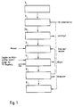
- Soil excavation 1 is fed to a screening plant 2.
- the coarse fraction screened off there may be disposed of elsewhere. If the coarse fraction is not contaminated, it can also be added to the fine material after it has been decontaminated.
- the fine material from the screening plant 2 is fed to a sorting plant 2a as required and separated from light goods therein.
- the fine material then passes into a refining drum 3 and is suspended there in water. Part of the suspension liquid from the process can be recycled into the refining drum 3.
- the soil suspension from the lauter drum 3 passes into a bioreactor system 4, which consists of a bubble bed reactor 7 and an associated gassing tank 8 (FIG. 2).
- soil suspension from the lauter drum 3 is charged with nutrients for the microorganisms, acid or alkali for pH control and with gas in order to create the best possible living conditions for the microorganisms, which degrade the various pollutants in that they biologically separate or convert them into harmless components.
- the solids concentration in the process according to the invention can be up to 60%.
- Gaseous conversion products are discharged with the exhaust air and, if necessary, subjected to a separate cleaning process in an exhaust air filter system, not shown in the drawing.
- the soil suspension is kept in suspension in the bioreactor system 4 by pumping around decanted suspension liquid.
- the duration of the treatment depends on the type of contamination of the soil in the following staggering: mineral oil contaminated soils 2 to 5 days, easily degradable PAK 5 to 10 days and poorly degradable PAHs 10 to 20 days and more.
- the soil suspension is thickened in the bubble bed reactor 7 of the bioreactor system 4 and then fed to a drainage system 5, the waste water of which is partially reused as a suspension liquid within the process. Waste water to be discharged from the process must be disposed of elsewhere.
- the dewatered fines, possibly together with the previously separated coarse fraction, are reused and brought to the bottom deposit 6.
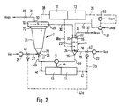
- FIG. 2 shows the overview of the bioreactor system 4, consisting of the hydrofluidized fluidized bed reactor 7 with the associated gassing container 8.
- the bubble bed reactor 7 consists of a conical container part 70, into which the suspension liquid is introduced from below via a liquid line 20.
- Container part 70 merges into a further conical container part 71, in which the biodegradation takes place in the individual decomposition zones of identical grain areas which form there and which partially overlap.
- the container parts 70 and 71 serve, after the biological pollutant degradation has ended, as a thickening container for the soil suspension.
- This is followed by a further conical container part 72, in the lower area of which a sedimentation zone is built up.
- the upper part of the bubble bed reactor 7 is formed by a round container 10.
- an acid / alkali inlet 15 is provided, to which an acid / alkali line 18 is connected.
- the acid or lye is conveyed into the gassing tank 8 by an acid pump 63 or lye pump 21.
- a gas inlet 16, to which a gas line 19 connects, is also installed in the gassing container 8.
- the gas is introduced into the gassing container 8 via a blower 22. It dissolves in the suspension liquid.
- the gassing container 8 has a liquid outlet 25 to which the liquid line 20 connects, via which the gassed suspension liquid is conveyed from the gassing container 8 into the bubble bed reactor 7 by means of a liquid pump 9, into which it is hydraulically connected via a liquid inlet 17 on the container part 70 is entered.
- the liquid outlet 25 is arranged on a pointed bottom 24, which closes the gassing container 8, which is otherwise designed as a round container 23, at the bottom.
- a gas inlet 26 is let in laterally, to which a gas line 27 is connected, which is provided with a blower 28 which, if necessary, pushes additional gas into the bubble bed reactor 7, which dissolves in the suspension liquid.
- the round container 10 of the bubble bed reactor 7 has a liquid outlet 29, to which a liquid line 30 connects, from which the decanted liquid from the bubble bed reactor 7 passes via a liquid inlet 31 into the gassing tank 8.
- the bubble bed reactor 7 and the gassing tank 8 also each have an exhaust gas outlet 32 or 33 for an exhaust gas line 34 or 35, which are equipped with valves 36 and 37, respectively. As already mentioned, the exhaust gas is disposed of elsewhere.
- the gassing container 8 is connected via a measuring line 38a and the bubble bed reactor 7 to a measuring line 38 with a measuring device 11.
- the measuring device 11 is assigned a control device 12 which is connected via a control line 39 to the acid pump 63 or the alkali pump 21.
- the temperature and the O2 content of the soil suspension in the bubble bed reactor 7 and via the measuring line 38a the pH of the suspension liquid in the gassing tank 8 are determined by sensors (not shown here) and transmitted to the measuring device 11.
- the pH value is kept constant or adapted to changed conditions via the control device 12, by regulating the acid / alkali supply into the gassing container 8 via the control line 39, which leads to the acid pump 63 or to the alkali pump 21.
- the bubble bed reactor 7 and the gassing container 8 are connected to a further measuring device 13 and associated control device 14 in terms of measurement and control technology.
- Via a measuring line 40 which leads from the liquid line 20 to the measuring device 13, measured values of flow, pressure and O2 content of the suspension liquid in the liquid line 20 are determined via suitable sensors, which are not shown here, and transmitted to the measuring device 13.
- a control line 41, 41a leads to the valve 43 in the gas line 27 of the bubble bed reactor 7 and a control line 41b to the valve 42 of the gas line 19 of the gassing container 8 for the purpose of regulating the O2 content.
- a control line 44 leads to the liquid pump 9 in the liquid line 20 in order to regulate the liquid supply according to pressure and quantity in accordance with the respective requirements of the bubble bed reactor 7.
- the bubble bed reactor 7 according to FIG. 2 is particularly suitable for fine fractions with a wide grain spectrum of 0 to 0.5 mm grain diameter because of its conical design.
- FIG. 3 shows a modified bubble bed reactor 7a, in which a longer cylindrical container part 46 is connected to a short conical container part 45, to which a second conical container part 47 is attached, which is connected to a second cylindrical container part 48.
- This modified Bubble bed reactor 7a is particularly suitable for fine fractions with a narrow grain spectrum of 20 »m to 300» m grain diameter.
- 3 is connected to the gassing container 8 via liquid line 20 and via liquid line 30.
- Liquid line 20 conveys the gassed suspension liquid from the gassing container 8 to the conical container part 45 of the bubble bed reactor 7a.
- Liquid line 30 leads the excess liquid from the cylindrical container part 48 of the bubble bed reactor 4 back into the gassing container 8.
- a temperature measuring device 65 and an oxygen measuring device 66 are integrated in the liquid line 30.
- the liquid line 20 contains a shut-off valve 53 arranged below the gassing container 8 and a shut-off valve 54 arranged below the bubble bed reactor 7a.
- a liquid pump 9 is integrated into the liquid line 20, which pumps a bypass line 49 containing a shut-off valve 52 above and above the liquid pump 9. downstream three-way valves 50, 51 can be bypassed when the liquid pump 9 is not or not temporarily operated.
- a temperature measuring device 55, a flow measuring device 56 and an oxygen measuring device 57 are accommodated in the liquid line 20. The latter is connected via a control line 58 to a shut-off valve 59 in the gas line 27 and forms an oxygen control circuit with the valve 59.
- a flow meter 69 is also assigned to the gas line 27.
- An exhaust pipe 35 leads out of the gassing container 8 and leads to a filter system, not shown in the drawing leads.
- An acid line 60 with an acid pump 63 and an alkali line 61 with an alkali pump 62 and a pH value measuring device 64 are connected to the gassing container part 8. The latter is connected to the pumps 62, 63 via control lines 67, 68 and forms pH control loops with these.
- the operation of the bubble bed reactor 7, 7a provides an oxygen supply which is adapted to the need for biodegradation.
- an O2 entry by gassing with air or pure oxygen in the gassing tank 8 and in the bubble bed reactor 7, 7a is provided if the O2 requirement is high.
- fumigation alone in the fumigation container 8 is sufficient.
- the circulation of the liquid can be dispensed with at times. Because this results in slow sedimentation of the soil suspension in the bubble bed reactor 7, 7a and a decrease in the O2 content in the soil suspension, the liquid circulation must be activated from time to time.
- a flow velocity of 4x10 ⁇ 4 to 8x10 ⁇ 4 m / s has been determined as optimal.
- the solids concentration in the bubble bed reactor 7, 7a was 500 g / l, while the solids concentration of the circulating suspension liquid was ⁇ 50 g / l.
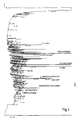
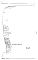
- FIGS. 4 and 5 show, even if one does not assign each characteristic PAH its characteristic pollutant component in detail, that an almost complete decontamination could be achieved overall.
- the concentration of the PAH usually measured according to the EPA "List of priority pollants" (MA Callahan et al. (1979), Water-related environmental fate of 129 priority pollutants, EPA Report -440 / 4-79-0296) was determined in Example reduced from 180 mg PAH / kg soil to 18 mg PAH / kg soil.
Abstract
Description
Die Erfindung betrifft ein Verfahren zur mikrobiologischen Bodenreinigung, wobei der verunreinigte Boden ausgehoben und in eine Grobfraktion und eine Feinfraktion getrennt wird, die Feinfraktion in einem Bioreaktor dekontaminiert wird, Betriebswasser in den Kreislauf zurückgeführt wird und der dekontaminierte Boden, gegebenenfalls nach Wiederzumischung der Grobfraktion, wieder angefüllt wird.The invention relates to a method for microbiological soil cleaning, in which the contaminated soil is excavated and separated into a coarse fraction and a fine fraction, the fine fraction is decontaminated in a bioreactor, process water is returned to the circuit and the decontaminated soil, if necessary after remixing the coarse fraction is filled.
Ein solches verfahren ist aus "Entwurf eines Slurry-Prozesses zur biotechnologischen Altlastensanierung", Altlastensanierung '90, Dritter Internationaler KfK/TNO-Kongress über Altlastensanierung, 10. - 14. Dezember 1990, Karlsruhe, Bundesrepublik Deutschland, Band II, Kluwer Academic Publishers, Dordrecht/Boston/London, Seiten 1103 und 1104, bekannt geworden. Bei diesem Slurry-Prozess ist es nachteilig, daß vier Bioreaktoren benötigt werden und zwar ein flüssigkeitsbewegter Reaktor und drei gasbewegte Reaktoren, um durch Öl verschmutzte Böden zu reinigen. Zur Beseitigung von polyzyklischen aromatischen Kohlenwasserstoffen aus Böden mit hohem Schluffanteil ist dieses Verfahren nicht vorgesehen und auch nicht geeignet.Such a procedure is based on "Design of a Slurry Process for Biotechnological Contaminated Site Remediation", Contaminated Site Remediation '90, Third International KfK / TNO Congress on Contaminated Site Remediation, December 10 - 14, 1990, Karlsruhe, Federal Republic of Germany, Volume II, Kluwer Academic Publishers, Dordrecht / Boston / London, pages 1103 and 1104. With this slurry process, it is disadvantageous that four bioreactors are required, namely a liquid-moving reactor and three gas-moving reactors, in order to clean floors contaminated by oil. This method is not intended and also not suitable for removing polycyclic aromatic hydrocarbons from soils with a high silt content.
Weiterhin sind aus der DE 37 33 341 A1 ein Verfahren und eine Einrichtung zur mikrobiologischen Bodenreinigung bekannt, um mit Kohlenwasserstoffen, insbesondere mit Mineralölen kontaminierte Böden, durch mikrobielle Oxidation zu reinigen, wobei den Böden neben Sauerstoff, Wasser, lösliche Nährstoffe sowie lösliche oder dispergierte Tenside, z.B. in einem "hydrodynamischen" Bioreaktor, zugeführt werden, um eine vollständige Mineralisierung der Mineralöle durch Veratmung zu CO₂ und H₂0 zu bewirken, wobei eine Regelung von Temperatur, pH-Wert, Sauerstoffkonzentration und Begasungsrate vorgesehen ist. Nachteilig ist hierbei, daß die vorgesehene durch Belüftung eingetragene Sauerstoffmenge bei weitem nicht dem Sauerstoffbedarf zur biologischen Mineraloxidaton entspricht. Darüberhinaus ist es nachteilig, daß das Verfahren wegen der Zugabe der Tenside verteuert wird und eine vergleichsweise aufwendige Regeleinrichtung benötigt wird. Zur Beseitigung von polyzyklischen aromatischen Kohlenwasserstoffen aus Böden mit hohem Schluffanteil ist dieses Verfahren nicht vorgesehen und auch nicht geeignet.Furthermore,
Außerdem ist dem Fachmann bekannt, daß Rührkesselreaktoren mit maximal 10 % und pneumatisch betriebene Reaktoren (Blasensäulen / Airliftreaktoren) mit maximal 25 % Feststoffgehalt wirtschaftlich betrieben werden können.It is also known to the person skilled in the art that stirred tank reactors with a maximum of 10% and pneumatically operated reactors (bubble columns / airlift reactors) with a maximum of 25% solids content can be operated economically.
Schließlich ist aus der DE 39 20 827 C1 eine Reinigungsanlage für kontaminierte Böden in Form einer gattungsfremden Regenerationsmiete zur Behandlung von naturfeuchten Böden bekannt, die einen Bewässerungskreislauf und einen Belüftungskreislauf aufweist und über Regeleinrichtungen verfügt, die die Feuchtigkeit und die mikrobielle Aktivität konstant halten, wobei wechselweise aerobe und anaerobe Behandlungsbedingungen Anwendung finden können. Bei dieser Anlage ist es schwierig, die Wetterbedingungen zu neutralisieren. Zur Beseitigung von polyzyklischen aromatischen Kohlenwasserstoffen aus Böden mit hohem Schluffanteil ist dieses Verfahren nicht vorgesehen und auch nicht geeignet.Finally, DE 39 20 827 C1 discloses a cleaning system for contaminated soils in the form of a non-generic regeneration rent for the treatment of naturally moist soils, which has an irrigation cycle and has a ventilation circuit and has control devices which keep the moisture and the microbial activity constant, whereby alternately aerobic and anaerobic treatment conditions can be used. With this system, it is difficult to neutralize the weather conditions. This method is not intended and also not suitable for removing polycyclic aromatic hydrocarbons from soils with a high silt content.
Der vorliegenden Erfindung liegt die Aufgabe zugrunde, die vorgenannten Nachteile der bekannten Verfahren zu vermeiden und ein einfacheres Verfahren zur mikrobiologischen Bodenreinigung zu entwickeln, das geringen Energiebedarf für die Suspendierung zur homogenen Bodenbehandlung bei hohen Feststoffgehalten der Bodensuspenison aufweist, bei dem für den biologischen Schadstoffabbau nur ein Bioreaktor für das Feingut erforderlich ist und mit dem insbesondere auch polyzyklische aromatische Kohlenwasserstoffe aus schluffhaltigen Böden abzuscheiden sind.The present invention is based on the object of avoiding the aforementioned disadvantages of the known methods and of developing a simpler method for microbiological soil cleaning which has low energy requirements for the suspension for homogeneous soil treatment at high solids contents of the soil suspension, with only one for biological pollutant degradation Bioreactor for the fine material is required and with which polycyclic aromatic hydrocarbons in particular can be separated from silty soils.
Diese Aufgabe wird ausgehend von einem Verfahren zur mikrobiologischen Bodenreinigung der eingangs genannten Gattung durch die kennzeichnenden Merkmale von Patentanspruch 1 gelöst.This object is achieved on the basis of a method for microbiological floor cleaning of the type mentioned at the outset by the characterizing features of patent claim 1.
Weiterbildungen des Verfahrens sind in den Unteransprüchen 2 bis 5 niedergelegt.Further developments of the method are set out in
Eine Vorrichtung zur Durchführung des Verfahrens weisen die Merkmale von Anspruch 6 aus.A device for performing the method has the features of claim 6.
In den Ansprüchen 7 und 8 sind Ausgestaltungen von Bioreaktoren gemäß Anspruch 6 ausgewiesen.Embodiments of bioreactors according to claim 6 are shown in
Bei einer Behandlung von kontaminierten Böden nach dem erfindungsgemäßen Verfahren und unter Anwendung der erfindungsgemäßen Vorrichtung lassen sich folgende Vorteile erreichen:
- geringer Energiebedarf für die Suspendierung zur homogenen Bodenbehandlung bei Feststoffkonzentrationen bis zu 60 % der Bodensuspension;
- optimale Auflösung der Bodenanteile in der Suspensionsflüssigkeit, so daß auch die Bodenanteile gut voneinander getrennt in der Bodensuspension vorliegen;
- durch die Behandlung des optimal aufgeschlossenen und aufgetrennten Bodens in der Suspension im Bioreaktor wird die Bioverfügbarkeit der im Boden vorhandenen Schadstoffe wesentlich verbessert;
- die Stoffaustauschvorgänge in dem suspendierten Bodenmaterial werden sehr stark beschleunigt und
- auch vergleichsweise schwer lösliche Schadstoffe sind den Mikroorganismen auch in Böden mit hohen Schluffanteilen direkt und unmittelbar zugänglich.
- low energy requirement for the suspension for homogeneous soil treatment at solids concentrations up to 60% of the soil suspension;
- optimal dissolution of the soil components in the suspension liquid, so that the soil components are also well separated from one another in the soil suspension;
- by treating the optimally digested and separated soil in the suspension in the bioreactor, the bioavailability of the pollutants present in the soil is significantly improved;
- the mass exchange processes in the suspended soil material are accelerated very strongly and
- Even comparatively poorly soluble pollutants are directly and immediately accessible to the microorganisms, even in soils with a high silt content.
Der gereinigte Boden kann nach der Entwässerung, gegebenenfalls einschließlich der zuvor abgetrennten, groben Bestandteile, wiederverwendet werden. Die Prozessflüssigkeit mit den darin enthaltenden Mikroorganismen kann weitgehend in umweltfreundlicher Weise innerhalb des Prozesses im Kreislauf geführt werden. Das Verfahren und die Vorrichtung sind auch zur Behandlung solcher Böden geeignet, die an Kokereistandorten mit schwer abbaubaren Kohlenwasserstoffen belastet sind. Beispielsweise gelingt es, die PAK-Verunreinigungen (PAK = polyzyklische aromatische Kohlenwasserstoffe) von Kokereiböden mit hohem Schluffanteil innerhalb nur weniger Wochen weitgehend abzubauen. Solche Böden mit sehr hohem Feinstkornanteil ließen sich bisher nur unvollständig durch die bekannten biologischen Dekontaminierungsmaßnahmen behandeln und sanieren.The cleaned soil can be reused after dewatering, if necessary including the previously separated, coarse components. The process liquid with the microorganisms contained therein can largely be circulated within the process in an environmentally friendly manner. The method and the device are also suitable for the treatment of soils which are contaminated with difficultly degradable hydrocarbons at coke oven sites. For example, the PAH contamination (PAH = polycyclic aromatic hydrocarbons) from coke-oven soils with a high silt content is largely reduced within just a few weeks. So far, such floors with a very high proportion of fine grains could only be treated and renovated incompletely using the known biological decontamination measures.
Die Erfindung wird nachfolgend anhand der Zeichnung und eines Beispiels näher beschrieben.The invention is described below with reference to the drawing and an example.
Es zeigen
- Figur 1
- das erfindungsgemäße Verfahren zur mikrobiologischen Bodenreinigung in einer schematischen Übersichtsdarstellung,
Figur 2- eine Bioreaktoranlage mit zugeordnetem Begasungsbehälter und Meß- und Regelzubehör, ebenfalls in einer schematischen Darstellung,
Figur 3- eine andere Ausgestaltung der Bioreaktoranlage,
- Figur 4
- ein Gaschromatogramm eines unbehandelten Kokereibodens und
Figur 5- ein Gaschromatogramm des erfindungsgemäß behandelten Kokereibodens.
- Figure 1
- the inventive method for microbiological floor cleaning in a schematic overview,
- Figure 2
- a bioreactor system with assigned gassing tank and measuring and control accessories, also in a schematic representation,
- Figure 3
- another design of the bioreactor system,
- Figure 4
- a gas chromatogram of an untreated coke oven floor and
- Figure 5
- a gas chromatogram of the coke oven floor treated according to the invention.
In Figur 1 ist ein Verfahrensschema zur mikrobiologischen Bodenreinigung gemäß der Erfindung abgebildet. Der Bodenaushub 1 wird einer Siebanlage 2 zugeführt. Die dort abgesiebte Grobfraktion wird gegebenenfalls anderweitig entsorgt. Wenn die Grobfraktion nicht kontaminiert ist, kann sie auch dem Feingut nach dessen abgeschlossener Dekontaminierung wieder zugemischt werden. Das Feingut aus der Siebanlage 2 wird bedarfsweise einer Sortieranlage 2a aufgegeben und darin von Leichtgut abgetrennt. Anschließend gelangt das Feingut in eine Läutertrommel 3 und wird dort in Wasser suspendiert. In die Läutertrommel 3 kann ein Teil der Suspensionsflüssigkeit aus dem Prozess im Kreislauf zurückgeführt werden. Die Bodensuspension aus der Läutertrommel 3 gelangt in eine Bioreaktoranlage 4, die aus einem Sprudelbettreaktor 7 und einem zugehörigen Begasungsbehälter 8 besteht (Figur 2). In die Bioreaktoranlage 4 wird Bodensuspension aus der Läutertrommel 3 mit Nährstoffe für die Mikroorganismen, Säure bzw. Lauge zur pH-Wert-Regelung und mit Gas beaufschlagt, um möglichst optimale Lebensbedingungen für die Mikroorganismen zu schaffen, die die verschiedenen Schadstoffe dadurch abbauen, daß sie diese biologisch in unschädliche Bestandteile auftrennen bzw. umwandeln. Überraschenderweise kann die Feststoffkonzentration beim erfindungsgemäßen Verfahren bis zu 60 % betragen.1 shows a process diagram for microbiological floor cleaning according to the invention. Soil excavation 1 is fed to a
Gasförmige Umwandlungsprodukte werden mit der Abluft ausgetragen und im Bedarfsfalle einem gesonderten Reinigungsprozess in einer in der Zeichnung nicht dargestellten Abluft-Filteranlage unterworfen. Die Bodensuspension wird in der Bioreaktoranlage 4 durch Umpumpen von dekantierter Suspensionsflüssigkeit in Suspension gehalten. Die Zeitdauer der Behandlung richtet sich nach der Art der Kontamination des Bodens in folgender Staffelung:
Zu Beginn dieser Zeitspannen wird jeweils überprüft, ob der vorgegebene Dekontaminierungsgrad erreicht ist.At the beginning of these periods, it is checked whether the specified degree of decontamination has been reached.
Nach Erreichen des vorgegebenen Dekontaminierungsgrades wird die Bodensuspension im Sprudelbettreaktor 7 der Bioreaktoranlage 4 eingedickt und dann einer Entwässerungsanlage 5 zugeführt, dessen Abwasser teilweise als Suspensionsflüssigkeit innerhalb des Prozesses wiederverwendet wird. Aus dem Prozess auszuschleusendes Abwasser ist einer anderweitigen Entsorgung zuzuführen. Das entwässerte Feingut wird, gegebenenfalls zusammen mit der zuvor abgetrennten Grobfraktion, wiederverwendet und zur Bodenablagerung 6 gebracht.After the specified degree of decontamination has been reached, the soil suspension is thickened in the
In Figur 2 ist die Bioreaktoranlage 4, bestehend aus dem hydraulisch angeströmten Sprudelbettreaktor 7 mit dem zugeordneten Begasungsbehälter 8, in einer Übersichtsdarstellung abgebildet. Der Sprudelbettreaktor 7 besteht aus einem konischen Behälterteil 70, in den die Suspensionsflüssigkeit von unten über eine Flüssigkeitsleitung 20 aufgegeben wird. Behälterteil 70 geht in einen weiteren konischen Behälterteil 71 über, in dem der Bioabbau in den einzelnen sich dort ausbildenden Abbauzonen gleichfälliger Kornbereiche, die sich teilweise überschneiden, erfolgt. Die Behälterteile 70 und 71 dienen, nachdem der biologische Schadstoffabbau beendet worden ist, als Eindickbehälter für die Bodensuspension. Daran schließt ein weiterer konischer Behälterteil 72 an, in dessen unteren Bereich sich eine Sedimentationszone aufbaut. Der obere Teil des Sprudelbettreaktors 7 wird von einen Rundbehälter 10 gebildet. Im Begasungsbehälter 8 ist ein Säure/Lauge-Einlaß 15 vorgesehen, an den eine Säure/Lauge-Leitung 18 angeschlossen ist. Die Säure bzw. Lauge wird von einer Säurepumpe 63 bzw. Laugepumpe 21 in den Begasungsbehälter 8 gefördert. Im Begasungsbehälter 8 ist weiterhin ein Gaseinlauf 16 angebracht, an den eine Gasleitung 19 anschließt. Das Gas wird über ein Gebläse 22 in den Begasungsbehälter 8 eingetragen. Es löst sich in der Suspensionsflüssigkeit. Schließlich verfügt der Begasungsbehälter 8 über einen Flüssigkeitsauslaß 25, an den die Flüssigkeitsleitung 20 anschließt, über die mittels einer Flüssigkeitspumpe 9 die begaste Suspensionsflüssigkeit aus dem Begasungsbehälter 8 in den Sprudelbettreaktor 7 gefördert wird, in den sie über einen Flüssigkeitseinlaß 17 am Behälterteil 70 hydraulisch eingetragen wird. Der Flüssigkeitsauslaß 25 ist an einem Spitzboden 24 angeordnet, der den Begasungsbehälter 8, der im übrigen als Rundbehälter 23 ausgebildet ist, nach unten abschließt. In den konischen Behälterteil 70 des Sprudelbettreaktors 7 ist ein Gaseinlaß 26 seitlich eingelassen, an den eine Gasleitung 27 anschließt, die mit einem Gebläse 28 versehen ist, das bei Bedarf zusätzliches Gas in den Sprudelbettreaktor 7 hineindrückt, das sich in der Suspensionsflüssigkeit löst. Der Rundbehälter 10 des Sprudelbettreaktors 7 weist einen Flüssigkeitsauslaß 29 auf, an den eine Flüssigkeitsleitung 30 anschließt, aus der die dekantierte Flüssigkeit aus dem Sprudelbettreaktor 7 über einen Flüssigkeitseinlaß 31 in den Begasungsbehälter 8 gelangt. Der Sprudelbettreaktor 7 und der Begasungsbehälter 8 verfügen weiterhin über je einen Abgasauslaß 32 bzw. 33 für je eine Abgasleitung 34 bzw. 35, die mit Ventilen 36 bzw. 37 bestückt sind. Das Abgas wird, wie bereits erwähnt, einer anderweitigen Entsorgung zugeführt. Der Begasungsbehälter 8 ist über eine Meßleitung 38a und der Sprudelbettreaktor 7 mit einer Meßleitung 38 mit einer Meßeinrichtung 11 verbunden. Der Meßeinrichtung 11 ist eine Regeleinrichtung 12 zugeordnet, die über eine Regelleitung 39 mit der Säurepumpe 63 bzw. der Laugepumpe 21 verbunden ist. Über die Meßleitung 38 werden die Temperatur und der O₂-Gehalt der Bodensuspension im Sprudelbettreaktor 7 und über die Meßleitung 38a der pH-Wert der Suspensionsflüssigkeit im Begasungsbehälter 8 von hier nicht dargestellten Meßwertgebern ermittelt und der Meßeinrichtung 11 übermittelt. Über die Regeleinrichtung 12 wird der pH-Wert konstant gehalten oder geänderten Bedingungen angepaßt, indem die Säure/Lauge-Zufuhr in den Begasungsbehälter 8 über die Regelleitung 39, die zur Säurepumpe 63 bzw. zur Laugepumpe 21 führt, eingeregelt wird. Weiterhin sind der Sprudelbettreaktor 7 sowie der Begasungsbehälter 8 meß- und regelungstechnisch an eine weiteren Meßeinrichtung 13 und zugehörige Re-geleinrichtung 14 angeschlossen. Über eine Meßleitung 40, die von der Flüssigkeitsleitung 20 zur Meßeinrichtung 13 führt, werden Meßwerte von Strömung, Druck und O₂-Gehalt der Suspensionsflüssigkeit in der Flüssigkeitsleitung 20 über geeignete Meßwertgeber, die hier nicht dargestellt sind, ermittelt und der Meßeinrichtung 13 übermittelt. Von der angeschlossenen Regeleinrichtung 14 führt eine Regelleitung 41, 41a zum Ventil 43 in der Gasleitung 27 des Sprudelbettreaktors 7 sowie eine Regelleitung 41b zum Ventil 42 der Gasleitung 19 des Begasungsbehälters 8 zwecks Einregelung des O₂-Gehaltes. Außerdem führt eine Regelleitung 44 zur Flüssigkeitspumpe 9 in der Flüssigkeitsleitung 20, um die Flüssigkeitszufuhr nach Druck und Menge dem jeweiligen Bedarf des Sprudelbettreaktors 7 entsprechend zu regulieren. Der Sprudelbettreaktor 7 gemäß Fig. 2 ist wegen seiner konischen Ausbildung insbesondere für Feinfraktionen mit einem breiten Kornspektrum von 0 bis 0,5 mm Korndurchmesser geeignet.FIG. 2 shows the overview of the bioreactor system 4, consisting of the hydrofluidized
In Figur 3 ist ein abgewandelter Sprudelbettreaktor 7a dargestellt, bei dem an einen kurzen konischen Behälterteil 45 ein längerer zylindrischer Behälterteil 46 anschließt, an dem ein zweiter konischer Behälterteil 47 befestigt ist, der mit einem zweiten zylindrischen Behälterteil 48 verbunden ist. Dieser abgewandelte Sprudelbettreaktor 7a ist insbesondere für Feinfraktionen mit einem engen Kornspektrum von 20 »m bis 300 »m Korndurchmesser geeignet. Der Spudelbettreaktor 7a in der Ausgestaltung gemäß Fig. 3 ist über Flüssigkeitsleitung 20 sowie über Flüssigkeitsleitung 30 mit dem Begasungsbehälter 8 verbunden. Flüssigkeitsleitung 20 fördert die begaste Suspensionsflüssigkeit aus dem Begasungsbehälter 8 zum konischen Behälterteil 45 des Sprudelbettreaktors 7a. Flüssigkeitsleitung 30 führt die Überschußflüssigkeit aus dem zylindrischen Behälterteil 48 des Sprudelbettreaktors 4 zurück in den Begasungsbehälter 8. In die Flüssigkeitsleitung 30 sind ein Temperaturmeßgerät 65 und ein Sauerstoffmeßgerät 66 integriert. Die Flüssigkeitsleitung 20 enthält ein unterhalb des Begasungsbehälters 8 angeordnetes Absperrventil 53 sowie ein unterhalb des Sprudelbettreaktors 7a angeordnetes Absperrventil 54. Weiterhin ist in die Flüssigkeitsleitung 20 eine Flüssigkeitspumpe 9 integriert, welche von einer ein Absperrventil 52 enthaltenden Umgehungsleitung 49 über der Flüssigkeitspumpe 9 vor- bzw. nachgeschaltete Dreiwegeventile 50, 51 umgehbar ist, wenn die Flüssigkeitspumpe 9 nicht oder zeitweilig nicht betrieben wird. Weiterhin sind in der Flüssigkeitsleitung 20 ein Temperaturmeßgerät 55, ein Durchflußmeßgerät 56 sowie ein Sauerstoffmeßgerät 57 untergebracht. Letzteres ist über eine Regelleitung 58 mit einem Absperrventil 59 in der Gasleitung 27 verbunden und bildet mit dem Ventil 59 einen Sauerstoff-Regelkreis. Der Gasleitung 27 ist weiterhin ein Durchflußmeßgerät 69 zugeordnet. Aus dem Begasungsbehälter 8 führt eine Abgasleitung 35 heraus, die zu einer in der Zeichnung nicht dargestellten Filteranlage führt. An dem Begasungsbehälterteil 8 sind eine Säureleitung 60 mit Säurepumpe 63 sowie eine Laugeleitung 61 mit Laugepumpe 62 sowie ein pH-Wert-Meßgerät 64 angeschlossen. Letzteres ist über Regelleitungen 67, 68 mit den Pumpen 62, 63 verbunden und bildet mit diesen pH-Wert-Regelkreise.FIG. 3 shows a modified
Der erfindungsgemäße Betrieb des Sprudelbettreaktors 7, 7a sieht eine an den Bedarf des biologischen Stoffabbaus angepaßte Sauerstoffversorgung vor. Für den aeroben Abbau ist bei hohem O₂-Bedarf ein O₂-Eintrag durch Begasung mit Luft oder Reinsauerstoff im Begasungsbehälter 8 und im Sprudelbettreaktor 7, 7a vorgesehen. Bei geringem O₂-Bedarf ist eine Begasung allein im Begasungsbehälter 8 ausreichend. Bei sehr geringem O₂-Bedarf kann zeitweise auf die Umwälzung der Flüssigkeit verzichtet werden. Weil dies ein langsames Sedimentieren der Bodensuspension im Sprudelbettreaktor 7, 7a und eine Abnahme des O₂-Gehaltes in der Bodensuspension zur Folge hat, muß die Flüssigkeitsumwälzung von Zeit zu Zeit aktiviert werden.The operation of the
Im Sprudelbettreaktor 7, 7a können wechselweise aerobe und anaerobe Bedingungen in der Bodensuspension eingestellt werden, so daß auch solche Bedingungen geschaffen werden können, die für den biologischen Abbau von höher halogenierten Kohlenwasserstoffen erforderlich sind.In the
Für die Behandlung eines Bodens mit einem Korndurchmesser < 300 »m und einer Partikeldichte von 2,6 g/cm³ ist eine Anströmgeschwindigkeit von 4x10 ⁻⁴ bis 8x10 ⁻⁴ m/s als optimal ermittelt worden. Die Feststoffkonzentration im Sprudelbettreaktor 7, 7a betrug dabei 500 g/l, während die Feststoffkonzentration der im Kreislauf geführten Suspensionsflüssigkeit < 50 g/l betrug. Das Bodenmaterial wurde von einem Standort einer ehemaligen Kokerei entnommen. Die durchgeführten biologischen Abbauversuche hatten zum Ergebnis, daß die im Boden ursprünglich enthaltenen PAK (PAK = polyzyklische aromatische Kohlenwasserstoffe), deren Anteile und Verteilung aus dem Gaschromatogramm gemäß Figur 4 entnommen werden können, nach einer Behandlung von 7 Tagen fast vollständig abgebaut werden konnten, wie das Gaschromatogramm der Figur 5 zeigt. Die Figuren 4 und 5 weisen aus, auch wenn man nicht im Einzelnen jedem auftretendem PAK seinen charakteristischen Schadstoffanteil zuordnet, daß insgesamt eine fast vollständige Dekontamination erreicht werden konnte.For the treatment of a soil with a grain diameter of <300 »m and a particle density of 2.6 g / cm³, a flow velocity of 4x10 ⁻⁴ to 8x10 ⁻⁴ m / s has been determined as optimal. The solids concentration in the
Die Konzentration der üblicherweise gemäß der EPA-"List of priority pollants" (M.A. Callahan et al.(1979), Water-related environmental fate of 129 priority pollutants, EPA-Report -440/4-79-0296) gemessenen PAK wurde im Beispiel von 180 mg PAK/kg Boden auf 18 mg PAK/kg Boden reduziert.The concentration of the PAH usually measured according to the EPA "List of priority pollants" (MA Callahan et al. (1979), Water-related environmental fate of 129 priority pollutants, EPA Report -440 / 4-79-0296) was determined in Example reduced from 180 mg PAH / kg soil to 18 mg PAH / kg soil.
- 11
- BodenaushubExcavation
- 22nd
- SiebanlageScreening plant
- 2a2a
- SortieranlageSorting system
- 33rd
- LäutertrommelRefining drum
- 44th
- BioreaktoranlageBioreactor plant
- 55
- EntwässerungsanlageDrainage system
- 66
- BodenablagerungSoil deposit
- 77
- SprudelbettreaktorBubble bed reactor
- 7a7a
- SprudelbettreaktorBubble bed reactor
- 88th
- BegasungsbehälterFumigation container
- 99
- FlüssigkeitspumpeLiquid pump
- 1010th
- RundbehälterRound container
- 1111
- MeßeinrichtungMeasuring device
- 1212th
- RegeleinrichtungControl device
- 1313
- MeßeinrichtungMeasuring device
- 1414
- RegeleinrichtungControl device
- 1515
- Säure/Lauge-EinlaßAcid / alkali inlet
- 1616
- GaseinlaßGas inlet
- 1717th
- FlüssigkeitseinlaßFluid inlet
- 1818th
- Säure/Lauge-LeitungAcid / alkali line
- 1919th
- GasleitungGas pipe
- 2020th
- FlüssigkeitsleitungLiquid line
- 2121
- LaugepumpeAlkaline pump
- 2222
- Gebläsefan
- 2323
- RundbehälterRound container
- 2424th
- SpitzbodenPointed bottom
- 2525th
- FlüssigkeitsauslaßFluid outlet
- 2626
- GaseinlaßGas inlet
- 2727
- GasleitungGas pipe
- 2828
- Gebläsefan
- 2929
- FlüssigkeitsauslaßFluid outlet
- 3030th
- FlüssigkeitsleitungLiquid line
- 3131
- FlüssigkeitseinlaßFluid inlet
- 3232
- AbgasauslaßExhaust outlet
- 3333
- AbgasauslaßExhaust outlet
- 3434
- AbgasleitungExhaust pipe
- 3535
- AbgasleitungExhaust pipe
- 3636
- VentilValve
- 3737
- VentilValve
- 3838
- MeßleitungMeasurement line
- 38a38a
- MeßleitungMeasurement line
- 3939
- RegelleitungControl line
- 4040
- MeßleitungMeasurement line
- 4141
- RegelleitungControl line
- 41a41a
- RegelleitungControl line
- 41b41b
- RegelleitungControl line
- 4242
- VentilValve
- 4343
- VentilValve
- 4444
- RegelleitungControl line
- 4545
- konischer Behälterteilconical container part
- 4646
- zylindrischer Behälterteilcylindrical container part
- 4747
- konischer Behälterteilconical container part
- 4848
- zylindrischer Behälterteilcylindrical container part
- 4949
- UmgehungsleitungBypass line
- 5050
- DreiwegeventilThree-way valve
- 5151
- DreiwegeventilThree-way valve
- 5252
- AbsperrventilShut-off valve
- 5353
- AbsperrventilShut-off valve
- 5454
- AbsperrventilShut-off valve
- 5555
- TemperaturmeßgerätTemperature measuring device
- 5656
- DurchflußmeßgerätFlow meter
- 5757
- SauerstoffmeßgerätOxygen meter
- 5858
- RegelleitungControl line
- 5959
- AbsperrventilShut-off valve
- 6060
- SäureleitungAcid line
- 6161
- LaugeleitungLaypipe
- 6262
- LaugepumpeAlkaline pump
- 6363
- SäurepumpeAcid pump
- 6464
- pH-Wert-MeßgerätpH meter
- 6565
- TemperaturmeßgerätTemperature measuring device
- 6666
- SauerstoffmeßgerätOxygen meter
- 6767
- RegelleitungControl line
- 6868
- RegelleitungControl line
- 6969
- DurchflußmeßgerätFlow meter
- 7070
- konischer Behälterteilconical container part
- 7171
- konischer Behälterteilconical container part
- 7272
- konischer Behälterteilconical container part
Claims (8)
- A process for microbiological soil decontamination, in which the contaminated soil is dug out and is separated into a coarse fraction and a fine fraction, and the fine fraction is decontaminated in a bioreactor, water from the process is returned to the circuit and the decontaminated soil is filled in once more, optionally after the coarse fraction has been mixed back in, characterised in thata) the coarse material > 0.5 mm is separated off in a sieving stage and optionally light material is separated off in a sorting stage;b) the fine fraction < 0.5 mm is suspended in a washing stage;c) biological decomposition of contaminants in the soil suspension takes place using aerobic or anaerobic micro-organisms in a bioreactor installation comprising a hydraulically operated spouted-bed reactor and a gassing container associated therewith, and the operational conditions thereof are monitored by control circuits for temperature, pH value and O₂ content of the soil suspension, and pressure and speed of the suspension liquid;d) the soil suspension is kept in suspension in the bioreactor installation by re-circulating decanted suspension liquid, until the pre-determined degree of decontamination is achieved;e) the soil suspension is concentrated in the spouted-bed reactor; andf) drying takes place in a drying stage.
- A process according to claim 1, characterised in that treatment in the bioreactor installation takes place using anaerobic micro-organisms and decontamination takes place in an anaerobically adjusted soil suspension, the gassing container and/or spouted-bed reactor being supplied with an inert gas.
- A process according to claims 1 and 2, characterised in that the soil suspension is adjusted alternately anaerobically and aerobically.
- A process according to claim 1 or 2, characterised in that liquid from the drying stage is returned to the washing stage.
- A process according to one of claims 1 to 3, characterised in that the waste gas from the spouted-bed reactor and the gassing container is purified in a filtering stage arranged downstream thereof.
- A device for carrying out the process according to claims 1 to 5, characterised in that a sieving installation (2) for separating off the coarse fraction, a sorting installation (2a) for removing light material and a washing drum (3) for suspending the fine fraction are connected, and are arranged in series together with a bioreactor installation (4) which is for biological decomposition of contaminants and which comprises a spouted-bed reactor (7, 7a) with an associated gassing container (8) and measuring and control devices (11, 12, 13, 14), and a drying installation (5) is arranged downstream thereof.
- A device according to claim 6, characterised in that the spouted-bed reactor comprises three conical container parts (70, 71, 72) arranged one above another and passing into a round container (10);- a gas inlet (26) for a gas line (27) with a fan (28), and a liquid inlet (17) for a liquid line (20) with a liquid pump (9), are arranged in the lower container part (70), and the spouted-bed reactor (7) is connected to the gassing container (8) via the liquid line (20), the gassing container being formed as a round container (23) with a pointed base (24) and a liquid outlet (25) and with a gas inlet (16) for a gas line (19) with a fan (22);- the round container (10) in the spouted-bed reactor (7) is provided with a liquid outlet (29) for a liquid line (30) which introduces the suspension liquid into the gassing container (8) through a liquid inlet (31);- the gassing container (8) also has an acid/lye inlet (15) to which there is connected an acid/lye line (18) which leads to an acid pump (63) and a lye pump (21);- the spouted-bed reactor (7) and the gassing container (8) each have a waste gas outlet (32, 33) for a respective waste gas line (34, 35) with a shut-off valve (36, 37);- the spouted-bed reactor (7) and the gassing container (8) are each connected for measurement and control to a measuring device (11) and a control device (12), the spouted-bed reactor (7) being connected via a measuring line (38) and the gassing container (8) being connected via a measuring line (38a) to the measuring device (11) and the control device (12), the latter devices being connected via a control line (39) to the acid pump (63) and the lye pump (21);- the spouted-bed reactor (7) and the gassing container (8) are also connected for measurement and control firstly to a further measuring device (13) via a measuring line (40) leading to the liquid line (20), and secondly to a further control device (14) which itself leads via a control line (41) to valves (43, 42) in the gas lines (19, 27) and via a control line (44) to the liquid pump (9) in the liquid line (20).
- A device according to claim 6, characterised in that the spouted-bed reactor comprises a conical container part (45), a cylindrical container part (46) connected thereto, a further conical container part (47) and a further cylindrical container part (48) connected thereto;- the gassing container (8) is associated with the spouted-bed reactor (7) and is connected thereto via a liquid line (20) containing shut-off valves (53, 54), in which line a liquid pump (9) is integrated, and with the aid of three-way valves (50, 51) the said line can be by-passed via a by-pass line (49) containing a shut-off valve (52);- a temperature-measuring device (55), a flow-measuring device (56) and an oxygen-measuring device (57) are associated with the liquid line (20), the oxygen-measuring device forming an oxygen-control circuit via a control line (58) with a shut-off valve (59) in the gas line (27);- an acid line (60) with an acid pump (63), a lye line (61) with a lye pump (62), and a pH-value measuring device (64) are connected to the gassing container (8), and the said pH-value measuring device forms pH-value control circuits with the pumps (62, 63) via control lines (67, 68);- the spouted-bed reactor (7a) and the gassing container (8) are connected via a liquid line (30) with an associated temperature-measuring device (65) and oxygen-measuring device (66).
Applications Claiming Priority (3)
| Application Number | Priority Date | Filing Date | Title |
|---|---|---|---|
| DE4129363 | 1991-09-04 | ||
| DE4129363A DE4129363A1 (en) | 1991-09-04 | 1991-09-04 | METHOD FOR MICROBIOLOGICAL FLOOR CLEANING |
| PCT/EP1992/002030 WO1993004794A1 (en) | 1991-09-04 | 1992-09-03 | Microbiological soil decontamination process |
Publications (2)
| Publication Number | Publication Date |
|---|---|
| EP0602096A1 EP0602096A1 (en) | 1994-06-22 |
| EP0602096B1 true EP0602096B1 (en) | 1995-12-27 |
Family
ID=6439817
Family Applications (1)
| Application Number | Title | Priority Date | Filing Date |
|---|---|---|---|
| EP92918309A Expired - Lifetime EP0602096B1 (en) | 1991-09-04 | 1992-09-03 | Microbiological soil decontamination process |
Country Status (5)
| Country | Link |
|---|---|
| EP (1) | EP0602096B1 (en) |
| AT (1) | ATE132063T1 (en) |
| CZ (1) | CZ219193A3 (en) |
| DE (2) | DE4129363A1 (en) |
| WO (1) | WO1993004794A1 (en) |
Families Citing this family (4)
| Publication number | Priority date | Publication date | Assignee | Title |
|---|---|---|---|---|
| DE4339875A1 (en) * | 1993-11-23 | 1995-05-24 | Hohnecker Helmut | Process for cleaning and processing contaminated goods |
| DE4437812C2 (en) * | 1994-10-12 | 1999-10-07 | Andreas Bartetzko | Two-stage process and device for decontaminating particulate materials |
| DE19514222A1 (en) * | 1995-04-15 | 1996-10-17 | Dechema | Stirred vessel bio-reactor for cleaning contaminated soil |
| NL1002311C2 (en) * | 1996-02-12 | 1997-08-13 | Heidemij Realisatie Bv | Method for predicting the result of a cleaning process. |
Family Cites Families (10)
| Publication number | Priority date | Publication date | Assignee | Title |
|---|---|---|---|---|
| EP0290661A1 (en) * | 1987-05-15 | 1988-11-17 | M. W. Kellogg Company | Three-phase reactor operation |
| DE3733341A1 (en) * | 1987-10-02 | 1989-04-13 | Wintershall Ag | METHOD FOR IMPROVING MICROBIAL CLEANING OF HYDROCARBONS, ESPECIALLY WITH MINERAL OIL CONTAMINATED BOEDES, BY MICROBIAL OXIDATION |
| DE3818398A1 (en) * | 1988-05-31 | 1989-12-14 | Xenex Ges Zur Biotechnischen S | Process and plant for the recultivation treatment of xenobiotically contaminated soil by means of microorganisms |
| DE3921066A1 (en) * | 1988-06-27 | 1989-12-28 | Rethmann Staedtereinigung Gmbh | Process and plant for microbiological decontamination of contaminated soils |
| NL193056C (en) * | 1988-11-07 | 1998-09-08 | Bird Engineering B V | Method and device for the separation and (bio) chemical treatment of solids. |
| DE3901100C1 (en) * | 1989-01-16 | 1990-06-13 | Santec Gmbh, 1000 Berlin, De | |
| DE3920827C1 (en) * | 1989-06-24 | 1990-05-03 | Peter Dipl.-Biol. Harborth | Decontamination of earth - by covering with foil pref. insulated and spraying earth with water and air under controlled conditions |
| DE59003167D1 (en) * | 1989-08-18 | 1993-11-25 | Terdekon Gmbh Erddekontaminier | METHOD FOR CLEANING AND PREPARING POLLUTED GOODS. |
| DE3941510A1 (en) * | 1989-12-15 | 1991-06-20 | Fraunhofer Ges Forschung | METHOD AND DEVICE FOR THE REMOVAL AND DESTRUCTION OF BIODEGRADABLE POLLUTANTS FROM SEWAGE |
| DE4001558C1 (en) * | 1990-01-20 | 1991-04-18 | Biodetox Mbh Gesellschaft Zur Biologischen Schadstoffentsorgung Mbh, 3061 Ahnsen, De | Decontaminating soil contg. mineral oil hydrocarbon - by three-stage biological degradation of contaminants under non-aerobic and aerobic conditions |
-
1991
- 1991-09-04 DE DE4129363A patent/DE4129363A1/en not_active Ceased
-
1992
- 1992-09-03 EP EP92918309A patent/EP0602096B1/en not_active Expired - Lifetime
- 1992-09-03 CZ CS932191A patent/CZ219193A3/en unknown
- 1992-09-03 WO PCT/EP1992/002030 patent/WO1993004794A1/en active IP Right Grant
- 1992-09-03 AT AT92918309T patent/ATE132063T1/en not_active IP Right Cessation
- 1992-09-03 DE DE59204865T patent/DE59204865D1/en not_active Expired - Fee Related
Also Published As
| Publication number | Publication date |
|---|---|
| DE4129363A1 (en) | 1993-03-11 |
| ATE132063T1 (en) | 1996-01-15 |
| DE59204865D1 (en) | 1996-02-08 |
| EP0602096A1 (en) | 1994-06-22 |
| WO1993004794A1 (en) | 1993-03-18 |
| CZ219193A3 (en) | 1994-07-13 |
Similar Documents
| Publication | Publication Date | Title |
|---|---|---|
| EP0046900B2 (en) | Method and apparatus for the biological purification of waste water | |
| DE2942112A1 (en) | METHOD FOR WATER TREATMENT WITH ACTIVATED SLUDGE | |
| DE3137055A1 (en) | "METHOD AND DEVICE FOR BIOLOGICAL WASTE WATER TREATMENT" | |
| DE3726201C2 (en) | Activated sludge treatment process for wastewater or industrial wastewater | |
| DE10352636B4 (en) | Process and plant for the treatment of waste water on ships | |
| DE4303529C2 (en) | Method and device for chemical-physical and / or biological-physical floor cleaning | |
| DE19723607C2 (en) | Process for the remediation of contaminated soils and sludges and device for carrying out the process | |
| EP0602096B1 (en) | Microbiological soil decontamination process | |
| US5071566A (en) | Process for the separation of solid phase from liquid substance, particularly for waste water purification | |
| EP0208253B1 (en) | Process and apparatus for the biological purification of waste water | |
| EP0354239A1 (en) | Installation and device for purifying contaminated soils. | |
| DE3933513C2 (en) | ||
| DE4240064C2 (en) | Waste water treatment process and plant | |
| DE60107299T2 (en) | PROCESS FOR CLEANING WATER FROM A KEROSINENSCHWEFELUNGSANLAGE | |
| DE4437812C2 (en) | Two-stage process and device for decontaminating particulate materials | |
| EP0265442A1 (en) | Process and plant for purifying waste water | |
| EP0659695B1 (en) | Method for conditioning sewage sludge | |
| DE4243627A1 (en) | Open pored mineral bulk material carrying immobilised microorganisms | |
| DE4333490A1 (en) | Process for soil remediation | |
| DE4235892C2 (en) | Expanded clay and / or expanded slate with immobilized microorganisms, their production and use | |
| EP0546015B1 (en) | Process for decontaminating loose substances in pieces | |
| DE10046959A1 (en) | Heavy industrial liquid effluent homogenized in reactor under turbulent conditions by compressed air and regulated introduction of radical agent | |
| EP2046689B8 (en) | Plant for the prepurification of contaminated water with integrated further treatment of the solids | |
| EP0534351A2 (en) | Process and plant for the treatment of highly concentrated ammoniacal waste water | |
| DE3438857C1 (en) | Process for the extraction and recycling of homogenized humus |
Legal Events
| Date | Code | Title | Description |
|---|---|---|---|
| PUAI | Public reference made under article 153(3) epc to a published international application that has entered the european phase |
Free format text: ORIGINAL CODE: 0009012 |
|
| 17P | Request for examination filed |
Effective date: 19930811 |
|
| AK | Designated contracting states |
Kind code of ref document: A1 Designated state(s): AT BE CH DE DK FR GB IT LI LU NL |
|
| 17Q | First examination report despatched |
Effective date: 19950413 |
|
| ITF | It: translation for a ep patent filed |
Owner name: FIAMMENGHI - DOMENIGHETTI |
|
| GRAA | (expected) grant |
Free format text: ORIGINAL CODE: 0009210 |
|
| AK | Designated contracting states |
Kind code of ref document: B1 Designated state(s): AT BE CH DE DK FR GB IT LI LU NL |
|
| PG25 | Lapsed in a contracting state [announced via postgrant information from national office to epo] |
Ref country code: DK Effective date: 19951227 |
|
| REF | Corresponds to: |
Ref document number: 132063 Country of ref document: AT Date of ref document: 19960115 Kind code of ref document: T |
|
| ET | Fr: translation filed | ||
| REF | Corresponds to: |
Ref document number: 59204865 Country of ref document: DE Date of ref document: 19960208 |
|
| GBT | Gb: translation of ep patent filed (gb section 77(6)(a)/1977) |
Effective date: 19960117 |
|
| PGFP | Annual fee paid to national office [announced via postgrant information from national office to epo] |
Ref country code: AT Payment date: 19960814 Year of fee payment: 5 |
|
| PGFP | Annual fee paid to national office [announced via postgrant information from national office to epo] |
Ref country code: CH Payment date: 19960827 Year of fee payment: 5 |
|
| PLBE | No opposition filed within time limit |
Free format text: ORIGINAL CODE: 0009261 |
|
| STAA | Information on the status of an ep patent application or granted ep patent |
Free format text: STATUS: NO OPPOSITION FILED WITHIN TIME LIMIT |
|
| 26N | No opposition filed | ||
| PG25 | Lapsed in a contracting state [announced via postgrant information from national office to epo] |
Ref country code: AT Free format text: LAPSE BECAUSE OF NON-PAYMENT OF DUE FEES Effective date: 19970903 |
|
| PG25 | Lapsed in a contracting state [announced via postgrant information from national office to epo] |
Ref country code: LI Free format text: LAPSE BECAUSE OF NON-PAYMENT OF DUE FEES Effective date: 19970930 Ref country code: CH Free format text: LAPSE BECAUSE OF NON-PAYMENT OF DUE FEES Effective date: 19970930 |
|
| REG | Reference to a national code |
Ref country code: CH Ref legal event code: PL |
|
| REG | Reference to a national code |
Ref country code: GB Ref legal event code: IF02 |
|
| PGFP | Annual fee paid to national office [announced via postgrant information from national office to epo] |
Ref country code: NL Payment date: 20020815 Year of fee payment: 11 Ref country code: GB Payment date: 20020815 Year of fee payment: 11 |
|
| PGFP | Annual fee paid to national office [announced via postgrant information from national office to epo] |
Ref country code: LU Payment date: 20020829 Year of fee payment: 11 |
|
| PG25 | Lapsed in a contracting state [announced via postgrant information from national office to epo] |
Ref country code: LU Free format text: LAPSE BECAUSE OF NON-PAYMENT OF DUE FEES Effective date: 20030903 Ref country code: GB Free format text: LAPSE BECAUSE OF NON-PAYMENT OF DUE FEES Effective date: 20030903 |
|
| PG25 | Lapsed in a contracting state [announced via postgrant information from national office to epo] |
Ref country code: NL Free format text: LAPSE BECAUSE OF NON-PAYMENT OF DUE FEES Effective date: 20040401 |
|
| GBPC | Gb: european patent ceased through non-payment of renewal fee | ||
| NLV4 | Nl: lapsed or anulled due to non-payment of the annual fee |
Effective date: 20040401 |
|
| PG25 | Lapsed in a contracting state [announced via postgrant information from national office to epo] |
Ref country code: IT Free format text: LAPSE BECAUSE OF NON-PAYMENT OF DUE FEES;WARNING: LAPSES OF ITALIAN PATENTS WITH EFFECTIVE DATE BEFORE 2007 MAY HAVE OCCURRED AT ANY TIME BEFORE 2007. THE CORRECT EFFECTIVE DATE MAY BE DIFFERENT FROM THE ONE RECORDED. Effective date: 20050903 |
|
| PGFP | Annual fee paid to national office [announced via postgrant information from national office to epo] |
Ref country code: DE Payment date: 20070822 Year of fee payment: 16 |
|
| PGFP | Annual fee paid to national office [announced via postgrant information from national office to epo] |
Ref country code: BE Payment date: 20071001 Year of fee payment: 16 |
|
| PGFP | Annual fee paid to national office [announced via postgrant information from national office to epo] |
Ref country code: FR Payment date: 20070812 Year of fee payment: 16 |
|
| BERE | Be: lapsed |
Owner name: *BERGWERKSVERBAND G.M.B.H. Effective date: 20080930 |
|
| REG | Reference to a national code |
Ref country code: FR Ref legal event code: ST Effective date: 20090529 |
|
| PG25 | Lapsed in a contracting state [announced via postgrant information from national office to epo] |
Ref country code: BE Free format text: LAPSE BECAUSE OF NON-PAYMENT OF DUE FEES Effective date: 20080930 |
|
| PG25 | Lapsed in a contracting state [announced via postgrant information from national office to epo] |
Ref country code: DE Free format text: LAPSE BECAUSE OF NON-PAYMENT OF DUE FEES Effective date: 20090401 |
|
| PG25 | Lapsed in a contracting state [announced via postgrant information from national office to epo] |
Ref country code: FR Free format text: LAPSE BECAUSE OF NON-PAYMENT OF DUE FEES Effective date: 20080930 |