EP0602012B1 - Prise pour tube cathodique - Google Patents
Prise pour tube cathodique Download PDFInfo
- Publication number
- EP0602012B1 EP0602012B1 EP94102648A EP94102648A EP0602012B1 EP 0602012 B1 EP0602012 B1 EP 0602012B1 EP 94102648 A EP94102648 A EP 94102648A EP 94102648 A EP94102648 A EP 94102648A EP 0602012 B1 EP0602012 B1 EP 0602012B1
- Authority
- EP
- European Patent Office
- Prior art keywords
- case
- cover
- high voltage
- voltage discharge
- ray tube
- Prior art date
- Legal status (The legal status is an assumption and is not a legal conclusion. Google has not performed a legal analysis and makes no representation as to the accuracy of the status listed.)
- Expired - Lifetime
Links
- 230000002159 abnormal effect Effects 0.000 description 1
- 230000007547 defect Effects 0.000 description 1
- 239000000463 material Substances 0.000 description 1
- 239000011347 resin Substances 0.000 description 1
- 229920005989 resin Polymers 0.000 description 1
Images
Classifications
-
- H—ELECTRICITY
- H01—ELECTRIC ELEMENTS
- H01R—ELECTRICALLY-CONDUCTIVE CONNECTIONS; STRUCTURAL ASSOCIATIONS OF A PLURALITY OF MUTUALLY-INSULATED ELECTRICAL CONNECTING ELEMENTS; COUPLING DEVICES; CURRENT COLLECTORS
- H01R33/00—Coupling devices specially adapted for supporting apparatus and having one part acting as a holder providing support and electrical connection via a counterpart which is structurally associated with the apparatus, e.g. lamp holders; Separate parts thereof
- H01R33/74—Devices having four or more poles, e.g. holders for compact fluorescent lamps
- H01R33/76—Holders with sockets, clips, or analogous contacts adapted for axially-sliding engagement with parallely-arranged pins, blades, or analogous contacts on counterpart, e.g. electronic tube socket
- H01R33/7664—Holders with sockets, clips, or analogous contacts adapted for axially-sliding engagement with parallely-arranged pins, blades, or analogous contacts on counterpart, e.g. electronic tube socket having additional guiding, adapting, shielding, anti-vibration or mounting means
Definitions
- the present invention relates to a cathode ray tube socket which is provided with a socket body having a plurality of contacts disposed in a circle and a high voltage discharge gap housing formed on one side of the socket body.
- a high voltage discharge gap housing is provided on one side of the socket body and the high voltage discharge gap housing comprises a case having housed therein discharge electrodes and a cover for covering the case as disclosed in U.S. Patent No. 4,649,315 or 4,822,301, for instance.
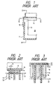
- EP-A-0268940 in order to increase the creeping distance between a high voltage electrode and a grounding electrode in the high voltage discharge gap to prevent the generation of an abnormal discharge along the interior surfaces of the case and the cover, there are provided on their inside surfaces ribs 13 and 14 as shown in Figs.
- ribs 14 of the cover 12 are each partially disposed between adjacent ribs 13 of the case 11. Where the spacing of each of the ribs 13 and 14 is small, discharge current does not flow along the wall surfaces of the case 11 and the cover 12 but instead it flows along a line joining the projecting ends of the ribs 13 and 14, skipping over grooves defined by them.
- the discharge current flows in zigzag along the inner surfaces of the cover 12 and the case 11 as indicated by the line 16 in Figs. 2 and 3.
- the spacing g is less than 1 mm, the discharge current flows straight as indicated by the line 17, and consequently, the creeping distance cannot essentially be maintained large.
- the prior art has a defect that miniaturization of the cathode ray tube socket reduces the creeping distance. Further, no measures have been taken against the discharge along the plane of contact between the case 11 and the cover 12.
- a gap is defined between opposed wall surfaces of the cover and the case received therein and a zigzag ridge which is interposed therebetween is formed on one of the opposed wall surfaces.
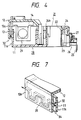
- Fig. 4 is a longitudinal-sectional view of a cathode ray tube socket.
- a socket body 21 of a resin material is disc-shaped and has a centrally-disposed hole 22, around which there are provided a plurality of holes 23 for receiving contacts 24.
- a terminal 25 of each contact 24 is led out on the back of the socket body 21, and an earth ring 27, which forms a low voltage discharge gap 26, is fitted into the socket body 21 at a position corresponding to the intermediate portion of the terminal 25.
- One of the contacts 24 is used as a contact for high voltage (focusing) use (hereinafter referred to as a high voltage contact) 24h, and a high voltage discharge gap housing 28 is provided on the side of the socket body 21 next to the high voltage contact 24h.
- the high voltage discharge gap housing 28 comprises a case 11 which accommodates a high voltage discharge electrode 29 and a cover 12 which receives substantially the upper half portion of the case 11 on its open end face.
- the case 11 is formed as a unitary structure with the socket body 21.
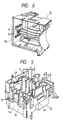
- Fig. 5 is a perspective view of the case 11, in which the high voltage discharge electrode 29 having a semi-spherical portion and a U-shaped discharge electrode on the ground side 30 are disposed opposite to each other.
- Fig. 6 is a perspective view of the cover 12.
- Fig. 7 shows only the side walls 11a and 12a of the case 11 and the cover 12 and the neighboring portions.
- a meandering ridge 32 is protrusively provided on the outside surface of the side wall 11a of the case 11.
- the top face of the meandering ridge 32 abuts against the inner surface of the side wall 12a of the cover 12, defining a gap 34 between the side walls 11a and 12a of the case 11 and the cover 12.
- the meandering ridge 32 may also be extended to the outside surfaces of other side walls of the case 11 as depicted in Fig. 5. Alternatively, such a meandering ridge 32 may be provided on the interior surface of the side wall of the cover 12.
- the creeping distance along the plane of contact between the side walls 11a and 12a of the case 11 and the cover 12 can be increased by providing the meandering ridge 32 between them.
Landscapes
- Connecting Device With Holders (AREA)
- Making Paper Articles (AREA)
- X-Ray Techniques (AREA)
Claims (1)
- Connecteur pour tube à rayons cathodiques qui est pourvu d'un corps de connecteur (21) comportant une pluralité de contacts (24) disposés suivant un cercle et d'une boîte de distance de décharge de haute tension (28) disposée d'un côté dudit corps de connecteur ;dans lequel ladite boîte de distance de décharge de haute tension (28) comprend un compartiment (11) formé d'un seul tenant avec ledit corps de connecteur et ayant une face d'extrémité ouverte, et un couvercle (12) qui est placé sur ledit compartiment du côté de ladite face d'extrémité ouverte de celui-ci ;dans lequel ledit compartiment (11) possède une pluralité de premières nervures de forme plate (13) formées sur une face de paroi intérieure dudit compartiment (11) de manière à s'étendre le long de celle-ci dans une direction transversale à une décharge de haute tension, dans une relation parallèle et espacée les unes par rapport aux autres ; etdans lequel ledit couvercle (12) possède une pluralité de secondes nervures de forme plate (14) formées sur une face de paroi intérieure dudit couvercle de manière à s'étendre le long de celui-ci dans une direction transversale à la décharge de haute tension ;caractérisé en ce que :
l'une des parois latérales opposées (11a, 12a) dudit compartiment (11) et dudit couvercle (12) comporte une nervure formant des méandres (32) s'étendant le long de celle-ci pour former entre eux une distance définie par ladite nervure (32).
Applications Claiming Priority (5)
| Application Number | Priority Date | Filing Date | Title |
|---|---|---|---|
| JP128608/88 | 1988-09-29 | ||
| JP1988128608U JPH0619178Y2 (ja) | 1988-09-29 | 1988-09-29 | 陰極線管ソケット |
| JP1988128607U JPH0619177Y2 (ja) | 1988-09-29 | 1988-09-29 | 陰極線管ソケット |
| JP128607/88 | 1988-09-29 | ||
| EP89117218A EP0361258B1 (fr) | 1988-09-29 | 1989-09-18 | Socle pour tube à rayon cathodique |
Related Parent Applications (1)
| Application Number | Title | Priority Date | Filing Date |
|---|---|---|---|
| EP89117218.1 Division | 1989-09-18 |
Publications (3)
| Publication Number | Publication Date |
|---|---|
| EP0602012A2 EP0602012A2 (fr) | 1994-06-15 |
| EP0602012A3 EP0602012A3 (en) | 1994-08-10 |
| EP0602012B1 true EP0602012B1 (fr) | 1996-12-04 |
Family
ID=26464215
Family Applications (2)
| Application Number | Title | Priority Date | Filing Date |
|---|---|---|---|
| EP89117218A Expired - Lifetime EP0361258B1 (fr) | 1988-09-29 | 1989-09-18 | Socle pour tube à rayon cathodique |
| EP94102648A Expired - Lifetime EP0602012B1 (fr) | 1988-09-29 | 1989-09-18 | Prise pour tube cathodique |
Family Applications Before (1)
| Application Number | Title | Priority Date | Filing Date |
|---|---|---|---|
| EP89117218A Expired - Lifetime EP0361258B1 (fr) | 1988-09-29 | 1989-09-18 | Socle pour tube à rayon cathodique |
Country Status (4)
| Country | Link |
|---|---|
| US (1) | US5007850A (fr) |
| EP (2) | EP0361258B1 (fr) |
| DE (2) | DE68927522T2 (fr) |
| ES (2) | ES2064408T3 (fr) |
Families Citing this family (1)
| Publication number | Priority date | Publication date | Assignee | Title |
|---|---|---|---|---|
| JP3126970B1 (ja) * | 2000-01-17 | 2001-01-22 | エスエムケイ株式会社 | Crtソケット |
Family Cites Families (7)
| Publication number | Priority date | Publication date | Assignee | Title |
|---|---|---|---|---|
| JPS594470Y2 (ja) * | 1978-05-10 | 1984-02-08 | 星電器製造株式会社 | 放電空隙付陰極線管ソケツト |
| US4298815A (en) * | 1979-11-09 | 1981-11-03 | Zenith Radio Corporation | Cathode ray tube socket with controlled spark gaps |
| US4573755A (en) * | 1982-06-24 | 1986-03-04 | American Plasticraft Co. | Spark gap device for a cathode ray tube socket |
| JPS6136975U (ja) * | 1984-08-08 | 1986-03-07 | 星電器製造株式会社 | 陰極線管ソケツト |
| KR890001665Y1 (ko) * | 1986-05-09 | 1989-04-07 | 주식회사금성사 | 음극 선관용 소켓 |
| JPH0231992Y2 (fr) * | 1986-11-21 | 1990-08-29 | ||
| GB2204747B (en) * | 1987-05-11 | 1991-06-26 | C M P | Diaphragm for electrical cable coupling devices |
-
1989
- 1989-09-14 US US07/407,081 patent/US5007850A/en not_active Expired - Lifetime
- 1989-09-18 DE DE68927522T patent/DE68927522T2/de not_active Expired - Lifetime
- 1989-09-18 EP EP89117218A patent/EP0361258B1/fr not_active Expired - Lifetime
- 1989-09-18 ES ES89117218T patent/ES2064408T3/es not_active Expired - Lifetime
- 1989-09-18 EP EP94102648A patent/EP0602012B1/fr not_active Expired - Lifetime
- 1989-09-18 ES ES94102648T patent/ES2095692T3/es not_active Expired - Lifetime
- 1989-09-18 DE DE68919968T patent/DE68919968T2/de not_active Expired - Lifetime
Also Published As
| Publication number | Publication date |
|---|---|
| EP0361258B1 (fr) | 1994-12-14 |
| ES2095692T3 (es) | 1997-02-16 |
| ES2064408T3 (es) | 1995-02-01 |
| EP0602012A3 (en) | 1994-08-10 |
| DE68919968D1 (de) | 1995-01-26 |
| EP0361258A2 (fr) | 1990-04-04 |
| EP0602012A2 (fr) | 1994-06-15 |
| DE68927522D1 (de) | 1997-01-16 |
| EP0361258A3 (en) | 1990-12-27 |
| DE68927522T2 (de) | 1997-04-30 |
| US5007850A (en) | 1991-04-16 |
| DE68919968T2 (de) | 1995-05-24 |
Similar Documents
| Publication | Publication Date | Title |
|---|---|---|
| KR100560483B1 (ko) | 이차 전지 | |
| US6432572B1 (en) | Battery valve and battery using the same | |
| US7052320B2 (en) | Electrical connector having shielding plates | |
| JP2005322648A (ja) | 二次電池モジュール | |
| CN220368096U (zh) | 电芯组件及电池 | |
| EP0602012B1 (fr) | Prise pour tube cathodique | |
| CA1041151A (fr) | Support et douille de tube electronique | |
| CA2255758A1 (fr) | Radiateur plat | |
| EP0173790B1 (fr) | Support de tube cathodique | |
| US3916238A (en) | Electron tube socket having spark gap structure | |
| US5588860A (en) | Bulb socket | |
| US6305988B1 (en) | CRT socket | |
| US4853544A (en) | Heat-resistant case for an ionization-type smoke detector and method of making the same | |
| EP0124830B1 (fr) | Panneau d'affichage à décharge dans les gaz du type self-scan | |
| US6528932B2 (en) | CRT socket with insulating interfit between focus and signal contacts | |
| US6443742B2 (en) | Printed circuit board-connecting connector with adjustable connections | |
| US4263118A (en) | Disinfection device | |
| US5117153A (en) | Cathode structure for electron gun | |
| JP2574135Y2 (ja) | 陰極線管用ソケット | |
| KR920003400Y1 (ko) | 음극선관 소켓 | |
| KR890001665Y1 (ko) | 음극 선관용 소켓 | |
| KR100245176B1 (ko) | 빔 형성 영역의 구조가 개선된 인라인전자총 | |
| KR890000831Y1 (ko) | 칼라 tv 수상관의 음극선관용 전자총 | |
| KR910007948Y1 (ko) | 음극선관용 전자총의 전극 구조체 | |
| KR890003728B1 (ko) | 칼라 수상관용 전자총의 내부방전 억제장치 |
Legal Events
| Date | Code | Title | Description |
|---|---|---|---|
| PUAI | Public reference made under article 153(3) epc to a published international application that has entered the european phase |
Free format text: ORIGINAL CODE: 0009012 |
|
| 17P | Request for examination filed |
Effective date: 19940222 |
|
| AC | Divisional application: reference to earlier application |
Ref document number: 361258 Country of ref document: EP |
|
| AK | Designated contracting states |
Kind code of ref document: A2 Designated state(s): DE ES FR GB LU |
|
| PUAL | Search report despatched |
Free format text: ORIGINAL CODE: 0009013 |
|
| RIN1 | Information on inventor provided before grant (corrected) |
Inventor name: NISHIKAWA, YASUNORI Inventor name: INABA, HIROFUMI,C/O HOSIDEN CORPORATION |
|
| AK | Designated contracting states |
Kind code of ref document: A3 Designated state(s): AT BE CH DE ES FR GB GR IT LI LU NL SE |
|
| GRAG | Despatch of communication of intention to grant |
Free format text: ORIGINAL CODE: EPIDOS AGRA |
|
| 17Q | First examination report despatched |
Effective date: 19960327 |
|
| GRAH | Despatch of communication of intention to grant a patent |
Free format text: ORIGINAL CODE: EPIDOS IGRA |
|
| GRAH | Despatch of communication of intention to grant a patent |
Free format text: ORIGINAL CODE: EPIDOS IGRA |
|
| RBV | Designated contracting states (corrected) |
Designated state(s): DE ES FR GB LU |
|
| GRAA | (expected) grant |
Free format text: ORIGINAL CODE: 0009210 |
|
| AC | Divisional application: reference to earlier application |
Ref document number: 361258 Country of ref document: EP |
|
| AK | Designated contracting states |
Kind code of ref document: B1 Designated state(s): DE ES FR GB LU |
|
| ET | Fr: translation filed | ||
| REF | Corresponds to: |
Ref document number: 68927522 Country of ref document: DE Date of ref document: 19970116 |
|
| REG | Reference to a national code |
Ref country code: ES Ref legal event code: FG2A Ref document number: 2095692 Country of ref document: ES Kind code of ref document: T3 |
|
| PG25 | Lapsed in a contracting state [announced via postgrant information from national office to epo] |
Ref country code: LU Free format text: LAPSE BECAUSE OF NON-PAYMENT OF DUE FEES Effective date: 19970930 |
|
| PLBE | No opposition filed within time limit |
Free format text: ORIGINAL CODE: 0009261 |
|
| STAA | Information on the status of an ep patent application or granted ep patent |
Free format text: STATUS: NO OPPOSITION FILED WITHIN TIME LIMIT |
|
| 26N | No opposition filed | ||
| REG | Reference to a national code |
Ref country code: GB Ref legal event code: IF02 |
|
| PGFP | Annual fee paid to national office [announced via postgrant information from national office to epo] |
Ref country code: ES Payment date: 20080901 Year of fee payment: 20 |
|
| PGFP | Annual fee paid to national office [announced via postgrant information from national office to epo] |
Ref country code: FR Payment date: 20080711 Year of fee payment: 20 |
|
| PGFP | Annual fee paid to national office [announced via postgrant information from national office to epo] |
Ref country code: GB Payment date: 20080924 Year of fee payment: 20 |
|
| PGFP | Annual fee paid to national office [announced via postgrant information from national office to epo] |
Ref country code: DE Payment date: 20080930 Year of fee payment: 20 |
|
| REG | Reference to a national code |
Ref country code: GB Ref legal event code: PE20 Expiry date: 20090917 |
|
| REG | Reference to a national code |
Ref country code: ES Ref legal event code: FD2A Effective date: 20090919 |
|
| PG25 | Lapsed in a contracting state [announced via postgrant information from national office to epo] |
Ref country code: GB Free format text: LAPSE BECAUSE OF EXPIRATION OF PROTECTION Effective date: 20090917 |
|
| PG25 | Lapsed in a contracting state [announced via postgrant information from national office to epo] |
Ref country code: ES Free format text: LAPSE BECAUSE OF EXPIRATION OF PROTECTION Effective date: 20090919 |