EP0601622A2 - Evaporateurs à écoulement en épingle pour des systèmes de climatisation de véhicule - Google Patents
Evaporateurs à écoulement en épingle pour des systèmes de climatisation de véhicule Download PDFInfo
- Publication number
- EP0601622A2 EP0601622A2 EP93203235A EP93203235A EP0601622A2 EP 0601622 A2 EP0601622 A2 EP 0601622A2 EP 93203235 A EP93203235 A EP 93203235A EP 93203235 A EP93203235 A EP 93203235A EP 0601622 A2 EP0601622 A2 EP 0601622A2
- Authority
- EP
- European Patent Office
- Prior art keywords
- header tube
- header
- evaporator
- tubes
- flow
- Prior art date
- Legal status (The legal status is an assumption and is not a legal conclusion. Google has not performed a legal analysis and makes no representation as to the accuracy of the status listed.)
- Withdrawn
Links
Images


Classifications
-
- F—MECHANICAL ENGINEERING; LIGHTING; HEATING; WEAPONS; BLASTING
- F28—HEAT EXCHANGE IN GENERAL
- F28F—DETAILS OF HEAT-EXCHANGE AND HEAT-TRANSFER APPARATUS, OF GENERAL APPLICATION
- F28F9/00—Casings; Header boxes; Auxiliary supports for elements; Auxiliary members within casings
- F28F9/02—Header boxes; End plates
- F28F9/026—Header boxes; End plates with static flow control means, e.g. with means for uniformly distributing heat exchange media into conduits
- F28F9/027—Header boxes; End plates with static flow control means, e.g. with means for uniformly distributing heat exchange media into conduits in the form of distribution pipes
-
- B—PERFORMING OPERATIONS; TRANSPORTING
- B60—VEHICLES IN GENERAL
- B60H—ARRANGEMENTS OF HEATING, COOLING, VENTILATING OR OTHER AIR-TREATING DEVICES SPECIALLY ADAPTED FOR PASSENGER OR GOODS SPACES OF VEHICLES
- B60H1/00—Heating, cooling or ventilating [HVAC] devices
- B60H1/00321—Heat exchangers for air-conditioning devices
- B60H1/00335—Heat exchangers for air-conditioning devices of the gas-air type
-
- B—PERFORMING OPERATIONS; TRANSPORTING
- B60—VEHICLES IN GENERAL
- B60H—ARRANGEMENTS OF HEATING, COOLING, VENTILATING OR OTHER AIR-TREATING DEVICES SPECIALLY ADAPTED FOR PASSENGER OR GOODS SPACES OF VEHICLES
- B60H1/00—Heating, cooling or ventilating [HVAC] devices
- B60H1/32—Cooling devices
- B60H1/3204—Cooling devices using compression
- B60H1/3227—Cooling devices using compression characterised by the arrangement or the type of heat exchanger, e.g. condenser, evaporator
-
- F—MECHANICAL ENGINEERING; LIGHTING; HEATING; WEAPONS; BLASTING
- F25—REFRIGERATION OR COOLING; COMBINED HEATING AND REFRIGERATION SYSTEMS; HEAT PUMP SYSTEMS; MANUFACTURE OR STORAGE OF ICE; LIQUEFACTION SOLIDIFICATION OF GASES
- F25B—REFRIGERATION MACHINES, PLANTS OR SYSTEMS; COMBINED HEATING AND REFRIGERATION SYSTEMS; HEAT PUMP SYSTEMS
- F25B39/00—Evaporators; Condensers
- F25B39/02—Evaporators
-
- F—MECHANICAL ENGINEERING; LIGHTING; HEATING; WEAPONS; BLASTING
- F28—HEAT EXCHANGE IN GENERAL
- F28D—HEAT-EXCHANGE APPARATUS, NOT PROVIDED FOR IN ANOTHER SUBCLASS, IN WHICH THE HEAT-EXCHANGE MEDIA DO NOT COME INTO DIRECT CONTACT
- F28D1/00—Heat-exchange apparatus having stationary conduit assemblies for one heat-exchange medium only, the media being in contact with different sides of the conduit wall, in which the other heat-exchange medium is a large body of fluid, e.g. domestic or motor car radiators
- F28D1/02—Heat-exchange apparatus having stationary conduit assemblies for one heat-exchange medium only, the media being in contact with different sides of the conduit wall, in which the other heat-exchange medium is a large body of fluid, e.g. domestic or motor car radiators with heat-exchange conduits immersed in the body of fluid
- F28D1/03—Heat-exchange apparatus having stationary conduit assemblies for one heat-exchange medium only, the media being in contact with different sides of the conduit wall, in which the other heat-exchange medium is a large body of fluid, e.g. domestic or motor car radiators with heat-exchange conduits immersed in the body of fluid with plate-like or laminated conduits
- F28D1/0308—Heat-exchange apparatus having stationary conduit assemblies for one heat-exchange medium only, the media being in contact with different sides of the conduit wall, in which the other heat-exchange medium is a large body of fluid, e.g. domestic or motor car radiators with heat-exchange conduits immersed in the body of fluid with plate-like or laminated conduits the conduits being formed by paired plates touching each other
- F28D1/0325—Heat-exchange apparatus having stationary conduit assemblies for one heat-exchange medium only, the media being in contact with different sides of the conduit wall, in which the other heat-exchange medium is a large body of fluid, e.g. domestic or motor car radiators with heat-exchange conduits immersed in the body of fluid with plate-like or laminated conduits the conduits being formed by paired plates touching each other the plates having lateral openings therein for circulation of the heat-exchange medium from one conduit to another
- F28D1/0333—Heat-exchange apparatus having stationary conduit assemblies for one heat-exchange medium only, the media being in contact with different sides of the conduit wall, in which the other heat-exchange medium is a large body of fluid, e.g. domestic or motor car radiators with heat-exchange conduits immersed in the body of fluid with plate-like or laminated conduits the conduits being formed by paired plates touching each other the plates having lateral openings therein for circulation of the heat-exchange medium from one conduit to another the plates having integrated connecting members
- F28D1/0341—Heat-exchange apparatus having stationary conduit assemblies for one heat-exchange medium only, the media being in contact with different sides of the conduit wall, in which the other heat-exchange medium is a large body of fluid, e.g. domestic or motor car radiators with heat-exchange conduits immersed in the body of fluid with plate-like or laminated conduits the conduits being formed by paired plates touching each other the plates having lateral openings therein for circulation of the heat-exchange medium from one conduit to another the plates having integrated connecting members with U-flow or serpentine-flow inside the conduits
Definitions
- This invention relates to a motor vehicle air conditioning system, and more particularly to such a system containing a refrigerant evaporator of the U-flow type of tube and fin construction as shown in EP-A-0138435.
- Such refrigerant evaporators utilise a number of U-shaped tubes which are interconnected at the ends thereof by two adjacent header tubes so as to form a bank of the interconnected U-shaped tubes in which refrigerant fluid supplied to one of the header tubes can pass in parallel flow through the U-shaped tubes into the other header tube.
- These U-flow refrigerant evaporators display good refrigerant fluid pressure drop characteristics when in operation.
- Such a bank of U-shaped tubes is essentially rectangular in shape and typically has been housed in a substantially rectangular-shaped box-like housing within the motor vehicle air-conditioning system in the motor vehicle.
- refrigerant evaporators it is customary in such refrigerant evaporators to sub-divide the two adjacent header tubes into separate multi-pass manifolds which interconnect the ends of the U-shaped tubes so that the refrigerant fluid is caused to flow in several passes, each containing several of the U-shaped tubes, backwards and forwards across the evaporator from one header tube to the other header tube.
- refrigerant evaporators it is customary to have an inlet for the refrigerant fluid entering one end of one of the header tubes, and an outlet for the refrigerant fluid exiting from the other end of that header tube or the other end of the adjacent header tube, depending on how many passes are provided in the evaporator.
- the inlet for the refrigerant fluid is at one end of one of the header tubes and the outlet is at the other end of the other header tube.
- An arrangement has been devised for the customary three-pass U-flow refrigerant evaporator whereby it is possible to have both the refrigerant flow inlet and the refrigerant fluid outlet positioned at the same end of the U-flow refrigerant evaporator, with the inlet positioned in one end of one header tube and the outlet positioned in the adjacent end of the other header tube.
- the inlet is formed by a tube which extends from said one end concentrically through said one header tube to a point approximately two-thirds of the way along that header tube, so that the refrigerant fluid enters that header tube at that point.
- the remaining third of said one header tube thus forms the first pass of the evaporator, with the refrigerant fluid passing through the U-tubes of that first pass into the other header tube to return back along the other header tube to a middle section of the U-flow refrigerant evaporator which forms the second pass of the evaporator.
- the refrigerant fluid passes through the U-tubes of that second pass back into an annular space in said one header tube surrounding the inlet tube, which annular space leads to a third pass of the evaporator.
- the refrigerant fluid entering the third pass of the evaporator then passes through the U-tubes of that third pass to return to the other header tube, and leaves the evaporator via the outlet in said adjacent end of the other header tube.
- a two-pass U-flow refrigerant evaporator comprises a number of U-shaped tubes which are interconnected at the ends thereof by two adjacent header tubes so as to form a bank of the interconnected U-shaped tubes in which refrigerant fluid supplied to one of the header tubes can pass in parallel flow through the U-shaped tubes into the other header tube, said one header tube being sub-divided by a transverse blocking member to form two separate plenum chambers, an inlet for said refrigerant fluid being positioned in one end of said other header tube and an outlet for said refrigerant fluid being positioned in an adjacent end of said one header tube in fluid communication with a second of said two plenum chambers, said inlet being formed as a tubular member which extends inside said other header tube substantially parallel to the axis of said other header tube, for substantially the length of said other header tube, and connects with a hollow transfer member which is located at an opposite end of the other header tube and is in fluid communication with an opposite end of said one header tube, so that ref
- the tubular member forming the inlet extends co-axially through the other header tube, and the hollow transfer member bridges said opposite ends of the header tubes, and is contained inside the evaporator by an end plate of the evaporator.
- the U-flow refrigerant evaporator is formed as an assembly of uniform U-flow flat tubes with air centres therebetween, the ends of which flat tubes are shaped into integral header tanks having opposed, aligned apertures therein, the evaporator being assembled as a stack of said flat tubes having the integral header tanks on the respective ends thereof in sealing contact with one another, with the opposed apertures therein aligned throughout the stack of flat tubes to form two adjacent header tubes, parallel to one another.
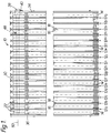
- FIG. 1 A preferred embodiment of a two-pass U-flow refrigerant evaporator 10 according to the present invention is shown in Figures 1 to 4 of the accompanying drawings.
- the U-flow refrigerant evaporator 10 comprises an assembly of uniform U-flow flat tubes 12, with air centres 14 interposed therebetween.
- the U-flow evaporator 10 is comprised of uniform U-flow flat tubes 12, each of which is fabricated from a pair of mating core plates exemplified by inner core plate 16 and outer core plate 18 shown in detail in Figures 2 to 4.
- the core plates 16, 18 are made from stampings of thin aluminium sheet or other suitable heat-transfer material, and are generally rectangular in plan view with rounded corners.
- the upper ends of the plates 16, 18 are each formed with an inlet opening 20 surrounded by a generally conical and truncated apertured protruberance 22, and an outlet opening 24 surrounded by a generally conical and truncated apertured protruberance 26.
- the generally conical and truncated apertured protruberances 22, 26 are connected to one another, as shown in Figures 1 and 2, to form a pair of integral header tubes 30, 32 for flow of refrigerant in either liquid phase or liquid/vapour phase through the flat tubes 12.
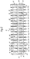
- the U-flow evaporator 10 shown in Figures 1 and 2 is made up of a total of seventeen uniform identical tubes 12a to 12q brazed together, a first end plate 34, and a second end plate 36.
- the first end plate 34 of the U-flow evaporator 10 has an inlet 38 into the integral header tube 30 at one end of the header tube 30, and an outlet 40 from the integral header tube 32 at an adjacent end of the header tube 32, as shown in Figure 2.
- a transverse blocking member 42 located in the integral header tube 32 between flat tubes 12h and 12i, which transverse blocking member 42 seals the respective outlet openings in flat tubes 12h and 12i, so as to divide the integral header tube 32 into two separate plenum chambers 44, 46, the first plenum chamber 44 being made up of the respective apertured protruberances 26 of the eight flat tubes 12a to 12h, forming a first pass of the U-flow evaporator 10, and the second plenum chamber 46 being made up of the respective apertured protruberances 26 of the nine flat tubes 12i to 12q, forming a second pass of the U-flow evaporator 10.
- the inlet 38 is formed as a tubular member 48 which extends inside the integral header tube 30 substantially parallel to, and co-axial with, a longitudinal axis 50 of the integral header tube 30, for substantially the length of the integral header tube 30, passing concentrically through all of the inlet openings 20 of the respective flat tubes 12a to 12q in the process.
- the tubular member has a diameter less than the diameter of each of the inlet openings 20 in the flat tubes 12, so defining an annular opening 52 in each of the respective inlet openings 20 through which refrigerant fluid can flow from one flat tube to the next flat tube along the integral header tube 30.
- the tubular member 48 connects with a hollow transfer member 54 which is located at an opposite end of the integral header tube 30 and is in fluid communication with an opposite end of the integral header tube 32, so that refrigerant fluid supplied to said inlet 38 passes along said tubular member 48, into said transfer member 54, and into the opposite end of the integral header tube 32.
- the hollow transfer member 54 forms part of the second end plate 36, the truncated apertured protruberances 22, 26 of the plate 16 of flat tube 12a being brazed to one wall 56 of the hollow transfer member 54.
- the wall 56 has two circular apertures 58,60 formed therein which are co-axially placed with respect to the longitudinal axes of the integral header tubes 30,32.
- Circular aperture 58 has a diameter such that the tubular member 48 is a push fit therein, and, as shown in Figure 4, the tubular member 48 terminates in an open end 62 adjacent the wall 56.
- the tubular member 48 is sealingly secured to the wall 56 by brazing, so as to prevent any bypass of refrigerant fluid leaving the open end 62 of the tubular member 48 into the inlet opening 20 of the flat tube 12a.
- the circular aperture 60 in the wall 56 has a diameter at least as great as the diameter of aperture 58, and freely permits the flow therethrough of refrigerant fluid entering the the hollow transfer member 54 through the open end 62 of the tubular member 48.
- Refrigerant fluid passing through the circular aperture 60 in the wall 56 of the hollow transfer member 54 enters the first plenum chamber 44 of the integral header tube 32, and then passes through the U-shaped flat tubes 12a to 12h interconnecting the first plenum chamber 44 with the integral header tube 30 and into the annular openings 52 of the integral header tube 30, thus traversing the first pass of the U-flow evaporator 10.
- the flow of refrigerant in each U-shaped flat tube 12a to 12h occurs through a passage 64 formed in the tube 12a on one side of a raised divider rib 66 formed on each of the core plates 16, 18 forming the tube 12a.
- the divider rib 66 is located in the centre of the tube 12a to form the flow passage 64 and a second flow passage 68 which communicates with the integral header tube 30.
- the refrigerant fluid then passes along the integral header tube 30 in the direction of the first end plate 34 through the annular openings 52 in the U-shaped flat tubes 12i to 12q, through the U-shaped flat tubes 12i to 12q interconnecting the integral header tube 30 with the second plenum chamber 46, and into the second plenum chamber 46, thus traversing the second pass of the U-flow evaporator 10.
- each of the U-shaped flat tubes 12i to 12q as exemplified by U-shaped flat tubes 12i and 12q shown in Figure 3, flow of refrigerant from the header tube 30 occurs through a passage 64' formed in each tube 12i to 12q on one side of a raised divider rib 66' formed on each of the core plates 16,18 forming each tube 12i to 12q.
- the divider rib 66' is located in the centre of each tube 12i to 12q to form the flow passage 64' and a second flow passage 68' which communicates with the second plenum chamber 46 of the integral header tube 32.
- the annular openings 52 and the outlet openings 24 of all of the tubes 12i to 12q are unobstructed, thus allowing free flow of the refrigerant fluid in the integral header tube 30 through all of the tubes 12i to 12q into the integral header tube 32.
- the refrigerant fluid finally leaves the U-flow evaporator 10 by the outlet 40 in the first end plate 34.
- the hollow transfer member could be formed as a separate item and be attached to the second end plate of the evaporator, instead of forming part of the end plate.
- the tubular inlet member is arranged co-axially within the integral header tube, provided that there is free access for refrigerant fluid flow through the inlet openings in the integral header tube around the tubular inlet member.
- a U-flow refrigerant evaporator as disclosed in Figures 1 to 4 can readily be assembled from standard, commercially-available U-flow evaporator plates as produced and manufactured by the applicants, said evaporator plates having heights of 204.4 mm (approximately 8 ins.), 234.3 mm (approximately 9 ins.) and 249.2 mm (approximately 10 ins.), with a minimum of extra parts being required.
Landscapes
- Engineering & Computer Science (AREA)
- Physics & Mathematics (AREA)
- Thermal Sciences (AREA)
- Mechanical Engineering (AREA)
- General Engineering & Computer Science (AREA)
- Heat-Exchange Devices With Radiators And Conduit Assemblies (AREA)
Applications Claiming Priority (2)
| Application Number | Priority Date | Filing Date | Title |
|---|---|---|---|
| GB9225899A GB2273552A (en) | 1992-12-11 | 1992-12-11 | U-flow evaporators for vehicle air-conditioning systems |
| GB9225899 | 1992-12-11 |
Publications (2)
| Publication Number | Publication Date |
|---|---|
| EP0601622A2 true EP0601622A2 (fr) | 1994-06-15 |
| EP0601622A3 EP0601622A3 (fr) | 1994-07-06 |
Family
ID=10726469
Family Applications (1)
| Application Number | Title | Priority Date | Filing Date |
|---|---|---|---|
| EP19930203235 Withdrawn EP0601622A3 (fr) | 1992-12-11 | 1993-11-18 | Evaporateurs à écoulement en épingle pour des systèmes de climatisation de véhicule |
Country Status (2)
| Country | Link |
|---|---|
| EP (1) | EP0601622A3 (fr) |
| GB (1) | GB2273552A (fr) |
Cited By (3)
| Publication number | Priority date | Publication date | Assignee | Title |
|---|---|---|---|---|
| DE19716836A1 (de) * | 1996-04-30 | 1997-11-06 | Valeo Climatisation | Plattenwärmetauscher, insbesondere Verdampfer für Klimatisierungskreislauf |
| EP0905467A2 (fr) * | 1997-09-24 | 1999-03-31 | Showa Aluminum Corporation | Evaporateur |
| CN107110620A (zh) * | 2014-12-26 | 2017-08-29 | 三电控股株式会社 | 热交换器 |
Families Citing this family (2)
| Publication number | Priority date | Publication date | Assignee | Title |
|---|---|---|---|---|
| CN105466249B (zh) * | 2015-03-03 | 2017-05-17 | 何六珠 | 一种模组式管板换热器及其换热方法 |
| JP6767620B2 (ja) * | 2016-10-21 | 2020-10-14 | パナソニックIpマネジメント株式会社 | 熱交換器およびそれを用いた冷凍システム |
Citations (5)
| Publication number | Priority date | Publication date | Assignee | Title |
|---|---|---|---|---|
| GB464165A (en) * | 1936-03-05 | 1937-04-13 | Fairey Aviat Co Ltd | Improvements in heat exchange apparatus such as oil coolers and radiators for internal combustion engines for aircraft |
| US4217953A (en) * | 1976-03-09 | 1980-08-19 | Nihon Radiator Co. Ltd. (Nihon Rajiecta Kabushiki Kaisha) | Parallel flow type evaporator |
| US4274482A (en) * | 1978-08-21 | 1981-06-23 | Nihon Radiator Co., Ltd. | Laminated evaporator |
| JPS6155596A (ja) * | 1984-08-24 | 1986-03-20 | Showa Alum Corp | 熱交換器 |
| US5024269A (en) * | 1989-08-24 | 1991-06-18 | Zexel Corporation | Laminated heat exchanger |
-
1992
- 1992-12-11 GB GB9225899A patent/GB2273552A/en not_active Withdrawn
-
1993
- 1993-11-18 EP EP19930203235 patent/EP0601622A3/fr not_active Withdrawn
Patent Citations (5)
| Publication number | Priority date | Publication date | Assignee | Title |
|---|---|---|---|---|
| GB464165A (en) * | 1936-03-05 | 1937-04-13 | Fairey Aviat Co Ltd | Improvements in heat exchange apparatus such as oil coolers and radiators for internal combustion engines for aircraft |
| US4217953A (en) * | 1976-03-09 | 1980-08-19 | Nihon Radiator Co. Ltd. (Nihon Rajiecta Kabushiki Kaisha) | Parallel flow type evaporator |
| US4274482A (en) * | 1978-08-21 | 1981-06-23 | Nihon Radiator Co., Ltd. | Laminated evaporator |
| JPS6155596A (ja) * | 1984-08-24 | 1986-03-20 | Showa Alum Corp | 熱交換器 |
| US5024269A (en) * | 1989-08-24 | 1991-06-18 | Zexel Corporation | Laminated heat exchanger |
Non-Patent Citations (1)
| Title |
|---|
| PATENT ABSTRACTS OF JAPAN vol. 10, no. 218 (M-503)(2274) 30 July 1986 & JP-A-61 055 596 (SHOWA ALUM CORP) 20 March 1986 * |
Cited By (6)
| Publication number | Priority date | Publication date | Assignee | Title |
|---|---|---|---|---|
| DE19716836A1 (de) * | 1996-04-30 | 1997-11-06 | Valeo Climatisation | Plattenwärmetauscher, insbesondere Verdampfer für Klimatisierungskreislauf |
| DE19716836B4 (de) * | 1996-04-30 | 2006-01-12 | Valeo Climatisation | Plattenwärmetauscher, insbesondere Verdampfer für Klimatisierungskreislauf |
| EP0905467A2 (fr) * | 1997-09-24 | 1999-03-31 | Showa Aluminum Corporation | Evaporateur |
| EP0905467A3 (fr) * | 1997-09-24 | 1999-08-04 | Showa Aluminum Corporation | Evaporateur |
| US6145587A (en) * | 1997-09-24 | 2000-11-14 | Showa Aluminum Corporation | Evaporator |
| CN107110620A (zh) * | 2014-12-26 | 2017-08-29 | 三电控股株式会社 | 热交换器 |
Also Published As
| Publication number | Publication date |
|---|---|
| EP0601622A3 (fr) | 1994-07-06 |
| GB2273552A (en) | 1994-06-22 |
| GB9225899D0 (en) | 1993-02-03 |
Similar Documents
| Publication | Publication Date | Title |
|---|---|---|
| CA2081695C (fr) | Evaporateur ou evaporateur/condenseur | |
| EP0563471B1 (fr) | Evaporateur | |
| EP0683373B1 (fr) | Echangeur de chaleur et procédé pour sa fabrication | |
| US5314013A (en) | Heat exchanger | |
| JP3713079B2 (ja) | 高効率、小体積の冷媒蒸発器 | |
| JP4554144B2 (ja) | 蒸発器 | |
| EP1397623B1 (fr) | Evaporateur, procede de fabrication afferent, collecteur pour ledit evaporateur et systeme de refrigeration | |
| US5203407A (en) | Vehicle-loaded parallel flow type heat exchanger | |
| US5341870A (en) | Evaporator or evaporator/condenser | |
| EP0930477B1 (fr) | Echangeur de chaleur biphasé à refroidissement par liquide | |
| US5101890A (en) | Heat exchanger | |
| US5323851A (en) | Parallel flow condenser with perforated webs | |
| US5579835A (en) | Heat exchanger and arrangement of tubes therefor | |
| EP0745822B1 (fr) | Echangeur de chaleur avec collecteur compartimenté | |
| US4775006A (en) | Heat exchanger, particularly a coolant evaporator | |
| EP0802383A2 (fr) | Echangeur de chaleur multitubulaire avec disposition particulière des tubes | |
| US6216773B1 (en) | Plate type heat exchange | |
| US5431217A (en) | Heat exchanger evaporator | |
| EP0601622A2 (fr) | Evaporateurs à écoulement en épingle pour des systèmes de climatisation de véhicule | |
| US6397938B1 (en) | Heat exchanger | |
| US5179845A (en) | Heat exchanger | |
| US5979547A (en) | Distribution device capable of uniformly distributing a medium to a plurality of tubes of a heat exchanger | |
| JPH0355490A (ja) | 熱交換器 | |
| EP0619467B1 (fr) | Evaporateur | |
| EP0619468B1 (fr) | Echangeur de chaleur-évaporateur |
Legal Events
| Date | Code | Title | Description |
|---|---|---|---|
| PUAI | Public reference made under article 153(3) epc to a published international application that has entered the european phase |
Free format text: ORIGINAL CODE: 0009012 |
|
| PUAL | Search report despatched |
Free format text: ORIGINAL CODE: 0009013 |
|
| AK | Designated contracting states |
Kind code of ref document: A2 Designated state(s): DE FR IT |
|
| AK | Designated contracting states |
Kind code of ref document: A3 Designated state(s): DE FR IT |
|
| 17P | Request for examination filed |
Effective date: 19950109 |
|
| STAA | Information on the status of an ep patent application or granted ep patent |
Free format text: STATUS: THE APPLICATION HAS BEEN WITHDRAWN |
|
| 18W | Application withdrawn |
Withdrawal date: 19951109 |