EP0601555B1 - Light quantity control device - Google Patents
Light quantity control device Download PDFInfo
- Publication number
- EP0601555B1 EP0601555B1 EP93119767A EP93119767A EP0601555B1 EP 0601555 B1 EP0601555 B1 EP 0601555B1 EP 93119767 A EP93119767 A EP 93119767A EP 93119767 A EP93119767 A EP 93119767A EP 0601555 B1 EP0601555 B1 EP 0601555B1
- Authority
- EP
- European Patent Office
- Prior art keywords
- control voltage
- motor
- circuit
- light quantity
- control
- Prior art date
- Legal status (The legal status is an assumption and is not a legal conclusion. Google has not performed a legal analysis and makes no representation as to the accuracy of the status listed.)
- Expired - Lifetime
Links
- 230000003287 optical effect Effects 0.000 claims description 4
- 238000001514 detection method Methods 0.000 claims description 3
- 238000013016 damping Methods 0.000 description 10
- 230000005291 magnetic effect Effects 0.000 description 7
- 230000009467 reduction Effects 0.000 description 7
- 230000004907 flux Effects 0.000 description 5
- 230000004069 differentiation Effects 0.000 description 4
- 230000005284 excitation Effects 0.000 description 4
- 230000008901 benefit Effects 0.000 description 3
- 238000005265 energy consumption Methods 0.000 description 3
- 230000006872 improvement Effects 0.000 description 3
- 230000006698 induction Effects 0.000 description 3
- 238000010586 diagram Methods 0.000 description 2
- 239000003302 ferromagnetic material Substances 0.000 description 2
- 230000003321 amplification Effects 0.000 description 1
- 230000000593 degrading effect Effects 0.000 description 1
- 230000007257 malfunction Effects 0.000 description 1
- 230000004048 modification Effects 0.000 description 1
- 238000012986 modification Methods 0.000 description 1
- 238000003199 nucleic acid amplification method Methods 0.000 description 1
Images


Classifications
-
- H—ELECTRICITY
- H04—ELECTRIC COMMUNICATION TECHNIQUE
- H04N—PICTORIAL COMMUNICATION, e.g. TELEVISION
- H04N23/00—Cameras or camera modules comprising electronic image sensors; Control thereof
- H04N23/70—Circuitry for compensating brightness variation in the scene
- H04N23/75—Circuitry for compensating brightness variation in the scene by influencing optical camera components
-
- G—PHYSICS
- G03—PHOTOGRAPHY; CINEMATOGRAPHY; ANALOGOUS TECHNIQUES USING WAVES OTHER THAN OPTICAL WAVES; ELECTROGRAPHY; HOLOGRAPHY
- G03B—APPARATUS OR ARRANGEMENTS FOR TAKING PHOTOGRAPHS OR FOR PROJECTING OR VIEWING THEM; APPARATUS OR ARRANGEMENTS EMPLOYING ANALOGOUS TECHNIQUES USING WAVES OTHER THAN OPTICAL WAVES; ACCESSORIES THEREFOR
- G03B9/00—Exposure-making shutters; Diaphragms
- G03B9/58—Means for varying duration of "open" period of shutter
- G03B9/60—Means for varying duration of "open" period of shutter by varying speed of movement of obturating members
Definitions
- This invention relates to a light quantity control device adapted for use in an optical apparatus such as a camera, an observation apparatus, a projection-type television set, or the like.
- the conventional diaphragm device mounted on a video camera or the like has, as shown by way of example in Figs. 3 and 4, diaphragm blades 37 and 38 arranged as light quantity control members and a motor 1 for bringing a quantity of light to a desired quantity by driving and controlling the diaphragm blades 37 and 38.
- the motor 1 is arranged to be controlled by a motor control voltage Vc output from a comparison computing circuit 6 arranged to compare a light quantity control signal Vs with a speed control signal.
- the motor 1 is provided with a rotor magnet 2, a driving coil 3 for rotating the rotor magnet 2, a damping coil 4 for detecting the rotational speed of the rotor magnet 2 and a Hall element 5 for detecting the position of rotation of the rotor magnet 2.
- the device is arranged as follows: When the rotor magnet 2 rotates, a speed detection signal which is generated by the damping coil 4 is negatively fed back to the comparison computing circuit 6 via an amplification circuit 9.
- the motor control voltage Vc output from the comparison computing circuit 6 is applied to one terminal of the driving coil 3, while a ground level constant voltage is applied to the other terminal of the driving coil 3.
- the output of the Hall element 5 which detects the rotation position of the rotor magnet 2 by detecting changes in density of the magnetic flux of the rotor magnet 2 is input as an aperture value signal Vo to an exposure control circuit (not shown) through a differential amplifier 8.
- Fig. 4 shows the mechanical arrangement of the conventional diaphragm device described above.
- a printed circuit board 31 is provided for the motor 1.
- a motor cap 32 is arranged to serve as a bearing plate for supporting one of shafts of the rotor magnet 2.
- a yoke 33 which is made of a ferromagnetic material is arranged to form a magnetic circuit in conjunction with the rotor magnet 2.
- a diaphragm base plate 34 is provided with an aperture part 34a and arranged to have the motor 1 secured thereto.
- a spring 35 is arranged to drive the diaphragm blades 37 and 38 in one direction through a driving arm 36.
- the driving arm 36 transmits the driving force of the rotor magnet 2 and that of the spring 35 to the diaphragm blades 37 and 38.
- a cover 39 is provided with an aperture part 39a.
- the diaphragm blades 37 and 38 have diaphragm aperture parts 37a and 38a formed respectively therein.
- a quantity of light passing through the aperture parts 34a and 39a is controlled by driving the diaphragm blades 37 and 38 with the driving force of the rotor magnet 2 and that of the spring 35 through the driving arm 36 to vary the area of an aperture formed jointly by the diaphragm aperture parts 37a and 38a of the two diaphragm blades 37 and 38.
- the rotor magnet 2 rotates in the direction of opening the diaphragm aperture (increasing the area of the aperture) to drive the diaphragm blades 37 and 38 to move in the aperture opening direction through the driving arm 36.
- the diaphragm blades 37 and 38a are driven by the spring force of the spring 35.
- the conventional diaphragm device however, always necessitates a sufficient torque for overcoming the spring force of the spring 35 in causing the diaphragm blades 37 and 38 to move in the direction of opening the diaphragm aperture.
- the device has presented the following problems:
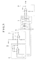
- Fig. 1 shows the arrangement of a light quantity control device arranged by way of example as an embodiment of this invention.
- a motor 11 includes a rotor magnet 12.
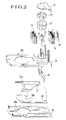
- the rotor magnet 12 is magnetized to have two poles in a radial direction and is arranged to drive and control light quantity control members (diaphragm blades) 27 and 28 shown in Fig. 2.
- Driving coils 13 and 14 are provided for rotating and driving the rotor magnet 12 by a voltage difference between a motor control voltage or first control voltage Vc which is an output of a comparison computing circuit or first circuit 16 and a motor control voltage or a second control voltage -Vc which is an output of an inverting amplifier circuit or second circuit 17 (because the motor control voltage Vc is applied to one end of each of the coils 13 and 14 while the motor control voltage -Vc is applied to the other end).
- a Hall element 15 is arranged to detect the rotation position of the rotor magnet 12 by linearly detecting the magnetic flux density of the rotor magnet 12 and to output an aperture value signal Vo through a differential amplifier 18.
- the comparison computing circuit 16 is arranged to compute and compare a speed control signal output from a differentiation circuit 19 with a light quantity control signal Vs and to output the motor control voltage Vc as a result of comparison.
- the inverting amplifier circuit 17 is arranged to invert the motor control voltage Vc output from the comparison computing circuit 16 with respect to a midpoint potential V DD and to apply to the driving coils 13 and 14 the above-stated control voltage -Vc which is opposite in polarity to the motor control voltage Vc and which has the same absolute value as the motor control voltage Vc.
- the differential amplifier 18 is arranged to amplify the output of the Hall element 15 and to output it as the aperture value signal Vo.
- the differentiation circuit 19 is arranged to form the speed control signal by using the aperture value signal Vo (linearly indicating the position of the rotor magnet 12).
- reference numeral 21 denotes a printed circuit board.
- a motor cap 22 serves as a bearing plate for supporting the shaft of the rotor magnet 12.
- a yoke 23 is made of a ferromagnetic material and is arranged to form a magnetic circuit in conjunction with the rotor magnet 12.
- a diaphragm base plate 24 has an aperture part 24a formed therein and the motor 11 secured thereto.
- a driving arm 26 is arranged to transmit the driving force of the rotor magnet 12 to the light quantity control members 27 and 28.
- a diaphragm cover 29 has an aperture part 29a and is arranged to accommodate the light quantity control members 27 and 28.
- the light quantity control signal Vs and the speed control signal which is the output of the differentiation circuit 19 are made into the motor control voltage Vc by the comparison computing circuit 16.
- the motor control voltage Vc is inverted by the inverting amplifier circuit 17 with respect to the midpoint potential V DD to obtain and output the control voltage -Vc.
- the driving coils 13 and 14 to which a voltage difference between the motor control voltages Vc and -Vc is applied are arranged to drive and control the rotor magnet 12 according to the voltage difference between the motor control voltages Vc and -Vc and the direction in which a current flows.
- the light quantity control members 27 and 28 are driven through the driving arm 26.
- the magnetic flux density of the rotor magnet 12 is linearly detected by the Hall element 15.
- the magnetic flux density thus detected is output through the differential amplifier 18 to be supplied as the aperture value signal Vo to an exposure control circuit or the like (not shown).
- the aperture value signal Vo which linearly represents the position of the rotator magnet 12 is input also to the differentiation circuit 19 to be negatively fed back to the comparison computing circuit 16 as the speed control signal, so that the light quantity controllability can be improved in respect of hunting, etc.
- the driving coil 3 is arranged to have the control voltage Vc applied to one end of it and a constant voltage of the ground level applied to the other end.
- This arrangement necessitates the control voltage Vc to be applied by making its polarity positive and negative relative to the constant voltage (ground level) instead of simply abolishing the use of the spring.
- the conventional arrangement therefore, requires a voltage (positive and negative voltages) about twice as high as the voltage required by the arrangement of this invention and thus results in an increase in size and weight of the device.
- the embodiment is arranged to obtain the speed control signal by using the linear position signal of the Hall element. That arrangement obviates the necessity of the damping coil of the conventional device.
- a space otherwise occupied by the damping coil is utilized to further wind the driving coil for an increase in torque. That arrangement permits reduction in electric energy consumption as well as reduction in size and weight of the device. (The driving coils 13 and 14 are connected in series or in parallel).
- the embodiment can be arranged by simply omitting the damping coil, without including the driving coil 14.
- This modification gives an advantage that the output of the Hall element, i.e., the aperture value signal, can be obtained without any excitation noise that results from mutual induction between the coils.
Landscapes
- Engineering & Computer Science (AREA)
- Multimedia (AREA)
- Signal Processing (AREA)
- Physics & Mathematics (AREA)
- General Physics & Mathematics (AREA)
- Diaphragms For Cameras (AREA)
- Facsimile Scanning Arrangements (AREA)
Description
Claims (8)
- A light quantity control device for an optical apparatus, comprising:characterized by(a) a motor (11) including a rotor (12) driven by a coil (13,14),(b) a plurality of light quantity control members (27, 28) arranged to be moved by said motor (11) serving as a drive source, and(c) a first circuit (16) arranged to generate a variable first control voltage (Vc) for controlling said motor (11),
a second circuit (17), whereinsaid first control voltage (Vc) is applied both to one end of said coil (13, 14) of said motor (11) in a direct manner and to said second circuit (17),wherein said second circuit (17) generates a second control voltage (-Vc) having a polarity opposite to said first control voltage (Vc), obtained by inverting said first control voltage (Vc), and having an absolute value approximately same as said first control voltage (Vc), and said second control voltage (-Vc) is applied to the other end of said coil (13, 14) of said motor (11), wherein both said first control voltage (Vc) and said second control voltage (-Vc) are simultaneously used to drive said motor (11), whereby the total voltage applied to said coil of said motor is obtained by adding said first control voltage (Vc) and said second control voltage (-Vc) together. - A device according to claim 1, characterized in that said rotor (12) is formed with a permanent magnet which is magnetized to have P poles and arranged to be driven within the range of a rotation angle of 360°/P.
- A device according to claim 1 or 2, characterized in thatsaid first circuit (16) is arranged to form the first control voltage (Vc) by performing a computation to compare the speed information derived from a position detection signal obtained by detecting the position of the rotor with light quantity control information (Vs).
- A device according to any of the preceding claims 1 to 3, characterized in thatsaid second circuit (17) includes an inverting amplifier circuit arranged to invert the first control voltage (Vc) with respect to a midpoint potential (VDD).
- A device according to claim 1, characterized by further comprisingspeed detecting means (15, 18, 19) for generating speed information.
- A device according to any of the preceding claims 1 to 4, characterized by further comprisingspeed detecting means (15, 18, 19) for generating speed information by using information on a change of the position of said light quantity control members (27, 28).
- A device according to claim 5 or 6, characterized in thatsaid speed detecting means (15, 18, 19) includes a detecting element (15) arranged to linearly detect the rotation position of said rotor (12) and obtains the speed information by differentiating an output of said detecting element (15).
- A device according to claim 7, characterized in that a Hall element is employed as said detecting element (15).
Applications Claiming Priority (2)
| Application Number | Priority Date | Filing Date | Title |
|---|---|---|---|
| JP4329548A JP2746509B2 (en) | 1992-12-09 | 1992-12-09 | Light control device |
| JP329548/92 | 1992-12-09 |
Publications (2)
| Publication Number | Publication Date |
|---|---|
| EP0601555A1 EP0601555A1 (en) | 1994-06-15 |
| EP0601555B1 true EP0601555B1 (en) | 1998-10-28 |
Family
ID=18222592
Family Applications (1)
| Application Number | Title | Priority Date | Filing Date |
|---|---|---|---|
| EP93119767A Expired - Lifetime EP0601555B1 (en) | 1992-12-09 | 1993-12-08 | Light quantity control device |
Country Status (5)
| Country | Link |
|---|---|
| US (1) | US6064432A (en) |
| EP (1) | EP0601555B1 (en) |
| JP (1) | JP2746509B2 (en) |
| CA (1) | CA2110646C (en) |
| DE (1) | DE69321809T2 (en) |
Families Citing this family (2)
| Publication number | Priority date | Publication date | Assignee | Title |
|---|---|---|---|---|
| JP3535450B2 (en) * | 2000-05-08 | 2004-06-07 | ワテック株式会社 | Replacement connection device between video camera and automatic iris lens in video camera and its detection circuit |
| US20050226612A1 (en) * | 2004-04-08 | 2005-10-13 | Asia Optical Co., Inc. | Automatic diaphragm assembly with a variable aperture for a lens |
Family Cites Families (7)
| Publication number | Priority date | Publication date | Assignee | Title |
|---|---|---|---|---|
| US4134653A (en) * | 1976-05-14 | 1979-01-16 | Copal Company Limited | Servoamplifier in an automatic diaphragm controlling device of a camera |
| US4084122A (en) * | 1976-10-20 | 1978-04-11 | A. B. Dick Company | Drive circuit for stepper motor |
| FR2440038A1 (en) * | 1978-10-27 | 1980-05-23 | Cannesson Roland | Alarm indicator for aircraft instrumentation - utilises micro torque motor controlled from logic circuit to drive indicator flag |
| JPS5850867A (en) * | 1981-09-22 | 1983-03-25 | Asahi Seimitsu Kk | Automatic aperture controller for cctv camera |
| JPS6064581A (en) * | 1983-09-19 | 1985-04-13 | Asahi Seimitsu Kk | Automatic aperture controller of lens for cctv camera controllable remotely |
| JPH02239782A (en) * | 1989-03-14 | 1990-09-21 | Canon Electron Inc | Luminous quantity controller |
| CA2058396C (en) * | 1990-12-25 | 1995-05-30 | Osamu Sato | Light-quantity control device |
-
1992
- 1992-12-09 JP JP4329548A patent/JP2746509B2/en not_active Expired - Lifetime
-
1993
- 1993-12-03 CA CA002110646A patent/CA2110646C/en not_active Expired - Lifetime
- 1993-12-08 DE DE69321809T patent/DE69321809T2/en not_active Expired - Lifetime
- 1993-12-08 EP EP93119767A patent/EP0601555B1/en not_active Expired - Lifetime
-
1995
- 1995-07-25 US US08/999,818 patent/US6064432A/en not_active Expired - Lifetime
Also Published As
| Publication number | Publication date |
|---|---|
| CA2110646C (en) | 1999-08-17 |
| JPH06175192A (en) | 1994-06-24 |
| DE69321809D1 (en) | 1998-12-03 |
| JP2746509B2 (en) | 1998-05-06 |
| CA2110646A1 (en) | 1994-06-10 |
| US6064432A (en) | 2000-05-16 |
| DE69321809T2 (en) | 1999-04-29 |
| EP0601555A1 (en) | 1994-06-15 |
Similar Documents
| Publication | Publication Date | Title |
|---|---|---|
| US4242608A (en) | Motor using Hall effect elements | |
| US5705873A (en) | Light-quantity control device | |
| KR880001721B1 (en) | Position detection signal generator | |
| CA1180751A (en) | Control circuit of brushless dc motor | |
| US6064432A (en) | Light quantity control device | |
| JP3173315B2 (en) | Drives and cameras and optical equipment | |
| EP0164742B1 (en) | Brushless motor | |
| EP0440927B1 (en) | Light quantity adjusting device | |
| US4417332A (en) | Turntable speed control | |
| JP3093010B2 (en) | Revolver fixed position stop device | |
| JP2937725B2 (en) | Light control device | |
| JP2683477B2 (en) | Light control device | |
| JP2937723B2 (en) | Light control device | |
| JPH0974779A (en) | Drive controller | |
| JP2937726B2 (en) | Light control device | |
| JPH09106314A (en) | Drive device and optical equipment using the same | |
| KR100227756B1 (en) | FG sensor circuit of V-Cal head drum motor | |
| JPH06334915A (en) | Camera system | |
| JPH1054837A (en) | Magnetoresistive sensor | |
| JPH07181558A (en) | Driving controller | |
| JP2937724B2 (en) | Light control device | |
| JPH07181557A (en) | Driving controller | |
| KR19980083513A (en) | Speed Control Circuit of V-Cal Head Drum Motor with FGF Sensor Removed | |
| JPS5831830B2 (en) | Brushless DC motor drive circuit | |
| JPH06258684A (en) | Light quantity controller |
Legal Events
| Date | Code | Title | Description |
|---|---|---|---|
| PUAI | Public reference made under article 153(3) epc to a published international application that has entered the european phase |
Free format text: ORIGINAL CODE: 0009012 |
|
| AK | Designated contracting states |
Kind code of ref document: A1 Designated state(s): DE FR GB |
|
| 17P | Request for examination filed |
Effective date: 19941027 |
|
| 17Q | First examination report despatched |
Effective date: 19950530 |
|
| GRAG | Despatch of communication of intention to grant |
Free format text: ORIGINAL CODE: EPIDOS AGRA |
|
| GRAG | Despatch of communication of intention to grant |
Free format text: ORIGINAL CODE: EPIDOS AGRA |
|
| GRAH | Despatch of communication of intention to grant a patent |
Free format text: ORIGINAL CODE: EPIDOS IGRA |
|
| GRAH | Despatch of communication of intention to grant a patent |
Free format text: ORIGINAL CODE: EPIDOS IGRA |
|
| GRAA | (expected) grant |
Free format text: ORIGINAL CODE: 0009210 |
|
| AK | Designated contracting states |
Kind code of ref document: B1 Designated state(s): DE FR GB |
|
| REF | Corresponds to: |
Ref document number: 69321809 Country of ref document: DE Date of ref document: 19981203 |
|
| ET | Fr: translation filed | ||
| PLBE | No opposition filed within time limit |
Free format text: ORIGINAL CODE: 0009261 |
|
| STAA | Information on the status of an ep patent application or granted ep patent |
Free format text: STATUS: NO OPPOSITION FILED WITHIN TIME LIMIT |
|
| 26N | No opposition filed | ||
| REG | Reference to a national code |
Ref country code: GB Ref legal event code: IF02 |
|
| PGFP | Annual fee paid to national office [announced via postgrant information from national office to epo] |
Ref country code: DE Payment date: 20121205 Year of fee payment: 20 |
|
| PGFP | Annual fee paid to national office [announced via postgrant information from national office to epo] |
Ref country code: GB Payment date: 20121205 Year of fee payment: 20 |
|
| PGFP | Annual fee paid to national office [announced via postgrant information from national office to epo] |
Ref country code: FR Payment date: 20130107 Year of fee payment: 20 |
|
| REG | Reference to a national code |
Ref country code: DE Ref legal event code: R071 Ref document number: 69321809 Country of ref document: DE |
|
| REG | Reference to a national code |
Ref country code: GB Ref legal event code: PE20 Expiry date: 20131207 |
|
| PG25 | Lapsed in a contracting state [announced via postgrant information from national office to epo] |
Ref country code: GB Free format text: LAPSE BECAUSE OF EXPIRATION OF PROTECTION Effective date: 20131207 Ref country code: DE Free format text: LAPSE BECAUSE OF EXPIRATION OF PROTECTION Effective date: 20131210 |