EP0600558A1 - Apparatus for preparing beverages such as coffee, soup, tea or the like - Google Patents
Apparatus for preparing beverages such as coffee, soup, tea or the like Download PDFInfo
- Publication number
- EP0600558A1 EP0600558A1 EP93203338A EP93203338A EP0600558A1 EP 0600558 A1 EP0600558 A1 EP 0600558A1 EP 93203338 A EP93203338 A EP 93203338A EP 93203338 A EP93203338 A EP 93203338A EP 0600558 A1 EP0600558 A1 EP 0600558A1
- Authority
- EP
- European Patent Office
- Prior art keywords
- liquid
- extracted
- housing part
- chamber
- extract
- Prior art date
- Legal status (The legal status is an assumption and is not a legal conclusion. Google has not performed a legal analysis and makes no representation as to the accuracy of the status listed.)
- Granted
Links
Images


Classifications
-
- A—HUMAN NECESSITIES
- A47—FURNITURE; DOMESTIC ARTICLES OR APPLIANCES; COFFEE MILLS; SPICE MILLS; SUCTION CLEANERS IN GENERAL
- A47J—KITCHEN EQUIPMENT; COFFEE MILLS; SPICE MILLS; APPARATUS FOR MAKING BEVERAGES
- A47J31/00—Apparatus for making beverages
- A47J31/24—Coffee-making apparatus in which hot water is passed through the filter under pressure, i.e. in which the coffee grounds are extracted under pressure
-
- A—HUMAN NECESSITIES
- A47—FURNITURE; DOMESTIC ARTICLES OR APPLIANCES; COFFEE MILLS; SPICE MILLS; SUCTION CLEANERS IN GENERAL
- A47J—KITCHEN EQUIPMENT; COFFEE MILLS; SPICE MILLS; APPARATUS FOR MAKING BEVERAGES
- A47J31/00—Apparatus for making beverages
- A47J31/40—Beverage-making apparatus with dispensing means for adding a measured quantity of ingredients, e.g. coffee, water, sugar, cocoa, milk, tea
- A47J31/402—Liquid dosing devices
Definitions
- This invention relates to a method of preparing beverages such as coffee, tea, soup or the like through extraction, in which the product to be extracted is accommodated in a chamber bounded at one axial end by a removable cover with an extract discharge opening, subsequently the product to be extracted is confined in this chamber by a piston from an axial end of the chamber that is located opposite the cover, whereafter liquid is supplied to the chamber via a liquid supply duct provided in the piston, the product to be extracted being extracted for a specified time of contact and the extract being discharged via the extract discharge opening.
- the liquid is continuously supplied to the chamber at a constant pressure and flow rate. Accordingly, the chamber is so dimensioned that, with this continuous supply of a specified desired total amount of liquid and with a specified amount of starting product to be extracted, a desired duration of the time of contact between the liquid and the product to be extracted is achieved.
- the fact is, however, that in different countries, particularly in the case of coffee, quite different requirements are imposed on the extract. For instance, in the United States 160 ml of extract is prepared with 5 grams of coffee, whilst in Denmark 15 grams of coffee are used to prepare the same amount of extract. As a consequence of this, it is impossible to make Danish coffee with an apparatus comprising a chamber whose dimensions are tailored to an American cup of coffee.
- the bottom surface of the chamber of the American apparatus is too small for that purpose. Conversely, it is impossible to make an American cup of coffee using an apparatus with a relatively large bottom surface, intended for the Danish market.
- the small amount of coffee in the relatively large chamber leads to a thin coffee bed in the chamber, which in turn has as a consequence that the duration of the time of contact between the liquid and the coffee bed becomes too short and accordingly a very weak extract is obtained.
- the object of the present invention is to provide a method of preparing beverages without the above-mentioned drawback.
- the method of the present invention is characterized in that a parameter corresponding with the amount of liquid supplied is measured and, depending on these measurements, the supply of liquid is regulated in such a manner that for a specified desired total amount of extract the time of contact between the liquid and the product to be extracted has a predetermined desired duration.
- the apparatuses that are used for carrying out the present method comprise several chambers. If only one cup of coffee is to be made, only one of the chambers is used, and if a pot of coffee is to be prepared, several chambers are used simultaneously.
- the duration of the time of contact is substantially equal for every amount of extract to be prepared, independently of the desired strength of the extract. This provides the advantage that the preparation of both small and large amounts of extract takes approximately the same amount of time.
- the only condition that needs to be adapted to the amount of extract to be prepared is the amount of starting product to be accommodated in the chambers for extraction.
- the duration of the time of contact is approx. 10-20 seconds at a liquid supply pressure of approx. 2 bar. Such a duration for the preparation of a specified amount of coffee has been found to be quite satisfactory in practice.
- the flow rate at which the liquid is supplied to the chamber can be regulated continuously.
- Such continuous regulation has the advantage that it can be realized simply and reliably with a flow control valve.
- the flow rate at which the liquid is supplied to the chamber is regulated in that the supply of liquid is periodically interrupted for a short period of time, in such a manner that the desired total amount of liquid is supplied over the total span of the desired time of contact.
- Such regulation leads to a pulsating supply of liquid to the chamber.
- the pulsating liquid stream causes whirls in the layer of starting product to be extracted, so that a better contact between the liquid and the starting product is realized.
- Such better contact between the liquid and the starting product to be extracted in turn has as a consequence that less starting product will suffice to obtain an extract of a particular strength.
- the present invention further relates to an apparatus for preparing beverages such as coffee, tea, soup or the like through extraction, comprising:
- the object of the present invention is to provide an apparatus of the above-described type without the drawbacks mentioned.
- the apparatus of the invention is characterized in that the chambers have equal dimensions and that the control is designed such that for a specified desired amount of extract the time of contact between the liquid and the product to be extracted has a predetermined desired duration.
- Such an apparatus can be supplied to all countries and the adaptation of the apparatus that is required to produce different qualities of coffee can be realized by means of the control.
- Such an apparatus moreover provides the advantage that the parts that are subject to wear, such as for instance filter plates on which the starting product to be extracted rests during the extraction process and through which the extract is discharged, and liquid distributor plates through which the liquid is introduced into the chamber, have standard dimensions. Accordingly, to be able to supply such parts at a later stage, only one type needs to be kept in stock, which results in considerable savings of cost.
- the duration of the time of contact can be regulated by virtue of the control being adapted for periodically opening and closing the shut-off valve, depending on the parameter measured.
- the liquid supply device may be provided with a flow control valve which can be controlled via the control, the control being adapted for controlling the flow control valve depending on the parameter measured, in such a manner that, given a specified desired total amount of extract, the desired duration of the time of contact between the liquid and the product to be extracted is achieved.
- Such a flow control valve is accurate, reliable in operation, and inexpensive.
- Dutch patent application 7502730 discloses an apparatus of a different type for preparing extracted beverages using the filtering method.
- the water supply is also interrupted periodically.
- the purpose of this is to reduce the required power for the water heater, which is designed as a through-flow heat exchanger.
- This publication does not disclose the interruption of the water supply for the purpose of obtaining a desired duration of the time of contact between the liquid and the product to be extracted.
- the problem for which the present invention provides a solution does not play a role in the Dutch patent application mentioned because it concerns an apparatus of the filtering type.
- the product to be extracted is accommodated in a chamber 1 bounded at one exial end by a removable cover 2 with an extract discharge opening 3.
- the product to be extracted is subsequently confined in this chamber by a piston 4 from an axial end of the chamber 1 located opposite the cover 2.
- a liquid supply duct 5 provided in the piston, liquid is supplied to the chamber 1 and the product to be extracted is extracted and the extract is discharged via the extract discharge opening 3.
- the extract is discharged into a cup 6.
- Such a method has the drawback that the size of the chamber 1 and the pressure at which the liquid is supplied determine to a large extent the strength of the extract to be prepared. Too much starting product in a chamber with too small a bottom surface leads to a longer time of contact between liquid and starting product and accordingly to a strong extract, whilst too little product in a chamber with a relatively large bottom surface leads to a very short time of contact between liquid and starting product and accordingly to a weak extract. Therefore, several chambers of different dimensions must be provided for the different extract qualities.
- a parameter is measured during the supply of liquid, which parameter corresponds with the amount of liquid supplied, and, depending on these measurements, the supply of liquid is regulated in such a manner that for a specified desired total amount of extract the time of contact between the liquid and the product to be extracted has a predetermined desired duration.
- the parameter being measured may for instance be the flow rate of the liquid supply but also other related quantities, such as the velocity of the liquid being supplied. In the present example, however, the flow rate is measured.
- the measurement of the flow rate can for instance be effectuated with a flow meter 7.
- the data measured by this flow meter are pased on to a control 8.
- the control 8 can then actuate means 9 and 10, respectively, for controlling the supply of liquid.
- extracts of different strengths can be prepared in a chamber 1 with standard dimensions.
- This provides the advantage that the apparatus for practicing the method is suitable for the preparation of different extract qualities, so that such an apparatus can be employed in the United States, where a weak extract is desired, in particular in the case of coffee, as well as in Denmark, where coffee is generally made somewhat stronger.
- the duration of the time of contact is substantially equal for all amounts of extract to be prepared.
- the flow rate at which the liquid is supplied to the chamber 1 can be regulated continuously. This may for instance be effected by means of a flow control valve 10 as shown in Fig. 2, controlled by control 8.
- the supply of liquid can be interrupted periodically for a short period, such that the desired total amount of liquid is supplied over the total span of the desired time of contact.
- shut-off valve 9 actuated by the control 8
- shut-off valve 9 being required anyhow for stopping the liquid supply.
- the present invention further relates to an apparatus which will be further clarified on the basis of an exemplary embodiment that is shown in Figs. 3-5.
- the apparatus in the exemplary embodiment comprises:
- the apparatus is characterized in that the chambers 1 have equal dimensions and that the control 8 is so designed that for a specified desired amount of extract the time of contact between the liquid and the product to be extracted has a predetermined duration.
- control 8 being adapted for periodically opening and closing the shut-off valve 9 depending on the flow rate measured.
- liquid supply device 11 being provided with a flow control valve 10 which can be controlled through the control 8.
- the apparatus comprises three liquid supply devices 11 each connected to a liquid supply duct 5.
- Each liquid supply device 11 comprises a flow meter 7 and a shut-off valve 9, optionally with a flow control valve 10, so that the time of contact can be controlled for each chamber 1 - and, if desired, for several chambers simultaneously - on an individual basis, as discussed with reference to Figs. 1 and 2.
- the apparatus comprises a liquid supply device 11 with three shut-off valves 9, which are each, optionally in combination with a flow control valve 10 as depicted in Fig. 2, connected to a liquid supply duct 5.
- the apparatus further comprises a flow meter 7 via which liquid is fed to the shut-off valves 9.
- the control 8 will control the shut-off valves 9 - and the flow control valves 10, if any - at least substantially simultaneously and in the same manner, so that the time of contact for each chamber 1 will assume a desired value within certain limits.
- the valves 9, 10 can also be controlled on the basis of the parameter values obtained with the flow meter 7, based on the assumption that the liquid supplied to the liquid supply device 11 will divide uniformly between the three chambers 1.
- the control 8 will control the shut-off valve 9 - and the flow control valve 10, if any - of the relevant chamber 1 on the basis of the information obtained with the flow meter 7, as discussed with reference to Figs. 1 and 2.
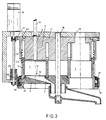
- the first housing part 13 comprising the chambers 1, of the embodiment shown in Figs. 3-4, is rotatable about a vertically oriented central axis 16 and is movable in axial direction.
- the first housing part 13 is accommodated between a fixedly arranged, second housing part 17, carrying the pistons 4, and a third housing part 2 serving as cover, which is likewise rotatable about the vertical axis 16 and movable in axial direction.
- the apparatus comprises a first drive motor 18, which is adapted for the circumferential positioning of the first housing part 13 and the third housing part 2, respectively, relative to the second housing part 17, and a second drive motor 19, which is adapted for the axial positioning of the first housing part 13 and the third housing part 2, respectively, relative to the second housing part 17.
- the control 8 of the apparatus is adapted for the positioning of the housing parts 2, 13, 17 relative to each other, whereby in a first position the chambers 1 can be filled with a product to be extracted via filling holes 29; in a second position the product to be extracted is confined in the chamber 1 between the cover 2 and the piston 4 and the supply of liquid and the discharge of extract can take place (left-hand portion of Fig. 3); and in a third position the extracted starting product can be removed (right-hand portion of Fig. 4).
- the thus functioning apparatus is suitable for preparing a single cup of coffee, with only a single chamber 1 being used, as well as for preparing a pot of coffee, with an extract being prepared in three chambers 1 at the same time.
- the apparatus is also suitable for preparing different kinds of cups of coffee in succession, with, for instance, two or three chambers 1 being respectively filled with different kinds of product to be extracted.
- every chamber 1 can be filled as desired via one of the three filling holes 29, with different kinds of product to be extracted being supplied via different filling holes 29.
- Fig. 5 schematically shows the operation of the apparatus according to Figs. 3 and 4.
- the apparatus essentially comprises a lower perforated plate, in this case a cover A, an intermediate piece B with chambers and an upper portion C with filling holes or pistons. These parts cooperate in the manner shown in Fig. 5D. Shown under it in Figs. E-M are the various positions of the parts during a movement cycle. In the starting position E, the perforated plate and the intermediate piece are interconnected. In the next position F, the chambers are filled via the intermediate piece, after which a confinement (position G) of the starting product in the chambers takes place by moving the intermediate piece (with the chambers) and the perforated plate towards the upper portion, after which a supply and discharge of medium takes place; Fig. 5H.
- Fig. 5K the cover A with the perforated plates is moved downwards, after which the ground coffee used is pushed away.
- Fig. 5M the intermediate piece is again moved downwards and connected to the perforated plate, thereby reaching the starting position of Fig. 5E.
- the second housing part 17 has a cylindrical axially extending outer surface and is exteriorly provided with a cylinder 20 rotatably connected therewith, this cylinder being provided externally with teeth 21 and internally with a thread 22.
- the thread 22 engages with an external thread 23 of the first housing part 13, and the second motor 19 engages the teeth 21 of the cylinder referred to.
- the apparatus comprises an outer ring 24 for positioning the first housing part 13 and the third housing part 2 relative to each other in axial and circumferential direction.
- the outer ring 24 is externally provided with teeth 25 meshing with a pinion 26 which can be driven by the first motor 18, and is internally provided with curved slots 27 adapted for cooperation with projections 28 at the circumference of the cover 2.
- the curved slots take care, upon rotation of the outer ring 24, of the axial movement of the third housing part 2 relative to the first housing part 13.
- the third housing part 2 optionally together with the first housing part 13, rotates into a different rotary position. Accordingly, when the first motor 18 is excited in a condition wherein the piston 4 is retracted from the chambers 1, the cover 2 carries the first housing part 13 along with it and via filling holes 29 the chambers 1 can be brought into communication with a supply device for coffee powder or the like, as is shown in the right-hand portion of Fig. 3.
- the first motor 18 When the first motor 18 is excited in a condition wherein the piston 4 is located in the chambers 1, the first housing part 13 is retained by the piston 4. The cover 2 is then forced to move relative to the first housing part 13, whilst a projection/projection guiding path construction, not further described here, ensures that the cover 2 first comes down relative to the first housing part 13 to clear the screen plate 15 from the chambers 1 and is subsequently moved tangentially relative to the first housing part 13. As a result, the coffee dregs left on the screen plate 15 after the coffee brewing process are removed. Upon excitation of the first motor 18 in opposite direction, the screen plate 15 is moved back into its position in the chambers 1 again and pressed down.
- Such an apparatus is stable in construction, so that the different movements of the housing parts can be carried out at high speed. A large amount of extract can therefore be produced in a short time.
Abstract
The invention further relates to an apparatus for carrying out the method, this apparatus comprising chambers (1) of equal dimensions.
Description
- This invention relates to a method of preparing beverages such as coffee, tea, soup or the like through extraction, in which the product to be extracted is accommodated in a chamber bounded at one axial end by a removable cover with an extract discharge opening, subsequently the product to be extracted is confined in this chamber by a piston from an axial end of the chamber that is located opposite the cover, whereafter liquid is supplied to the chamber via a liquid supply duct provided in the piston, the product to be extracted being extracted for a specified time of contact and the extract being discharged via the extract discharge opening.
- Such a method is disclosed in European patent application 0 369 542. The known method, which is quite satisfactory as such, is susceptible to further improvement.
- In the known method the liquid is continuously supplied to the chamber at a constant pressure and flow rate. Accordingly, the chamber is so dimensioned that, with this continuous supply of a specified desired total amount of liquid and with a specified amount of starting product to be extracted, a desired duration of the time of contact between the liquid and the product to be extracted is achieved. The fact is, however, that in different countries, particularly in the case of coffee, quite different requirements are imposed on the extract. For instance, in the United States 160 ml of extract is prepared with 5 grams of coffee, whilst in Denmark 15 grams of coffee are used to prepare the same amount of extract. As a consequence of this, it is impossible to make Danish coffee with an apparatus comprising a chamber whose dimensions are tailored to an American cup of coffee. The bottom surface of the chamber of the American apparatus is too small for that purpose. Conversely, it is impossible to make an American cup of coffee using an apparatus with a relatively large bottom surface, intended for the Danish market. The small amount of coffee in the relatively large chamber leads to a thin coffee bed in the chamber, which in turn has as a consequence that the duration of the time of contact between the liquid and the coffee bed becomes too short and accordingly a very weak extract is obtained.
- The object of the present invention is to provide a method of preparing beverages without the above-mentioned drawback.
- To that end, the method of the present invention is characterized in that a parameter corresponding with the amount of liquid supplied is measured and, depending on these measurements, the supply of liquid is regulated in such a manner that for a specified desired total amount of extract the time of contact between the liquid and the product to be extracted has a predetermined desired duration.
- Generally, the apparatuses that are used for carrying out the present method comprise several chambers. If only one cup of coffee is to be made, only one of the chambers is used, and if a pot of coffee is to be prepared, several chambers are used simultaneously.
- It is particularly advantageous, in accordance with a further elaboration of the invention, if the duration of the time of contact is substantially equal for every amount of extract to be prepared, independently of the desired strength of the extract. This provides the advantage that the preparation of both small and large amounts of extract takes approximately the same amount of time. The only condition that needs to be adapted to the amount of extract to be prepared is the amount of starting product to be accommodated in the chambers for extraction.
- In further elaboration of the invention, the duration of the time of contact is approx. 10-20 seconds at a liquid supply pressure of approx. 2 bar. Such a duration for the preparation of a specified amount of coffee has been found to be quite satisfactory in practice.
- In accordance with a further elaboration of the present invention, the flow rate at which the liquid is supplied to the chamber can be regulated continuously. Such continuous regulation has the advantage that it can be realized simply and reliably with a flow control valve.
- In accordance with a further elaboration of the invention, however, it is particularly advantageous if the flow rate at which the liquid is supplied to the chamber is regulated in that the supply of liquid is periodically interrupted for a short period of time, in such a manner that the desired total amount of liquid is supplied over the total span of the desired time of contact.
- Such regulation leads to a pulsating supply of liquid to the chamber. The pulsating liquid stream causes whirls in the layer of starting product to be extracted, so that a better contact between the liquid and the starting product is realized. Such better contact between the liquid and the starting product to be extracted in turn has as a consequence that less starting product will suffice to obtain an extract of a particular strength.
- The present invention further relates to an apparatus for preparing beverages such as coffee, tea, soup or the like through extraction, comprising:
- a first housing part with at least two chambers which are adapted for receiving a starting product to be extracted and which are each provided at least at one axial end thereof with an opening which is closable with a cover comprising an extract discharge opening;
- at least two pistons each being slidable relative to the chambers in axial direction of the respective chambers, and which are each adapted for confining in the chamber an amount of starting product to be extracted, the chamber being bounded by the chamber walls, the cover and the piston;
- at least one liquid supply device comprising a meter for measuring a parameter corresponding with the amount of liquid supplied and at least one shut-off valve for interrupting the supply of liquid, the liquid supply device being connectible by an inlet thereof to a liquid source, such as for instance the water supply system, and being connectible by at least one outlet thereof to liquid supply ducts provided in the pistons, these liquid supply ducts being adapted for supplying liquid to the relevant chamber; and
- a control adapted for controlling the entire apparatus.
- Such an apparatus is likewise disclosed in European patent application 0 369 542. The known apparatus has a drawback in that the different chambers thereof have mutually different dimensions. Moreover, it is impossible to produce a single type of apparatus for all countries on account of the different requirements imposed on e.g. coffee in different countries. This means that in order to be able to meet the desires of the different countries, a variety of molding dies are required for the production of the apparatus, which is mostly manufactured from synthetic material. This entails considerable additional costs, which is a major disadvantage.
- Accordingly, the object of the present invention is to provide an apparatus of the above-described type without the drawbacks mentioned.
- To that end, the apparatus of the invention is characterized in that the chambers have equal dimensions and that the control is designed such that for a specified desired amount of extract the time of contact between the liquid and the product to be extracted has a predetermined desired duration.
- Such an apparatus can be supplied to all countries and the adaptation of the apparatus that is required to produce different qualities of coffee can be realized by means of the control.
- Such an apparatus moreover provides the advantage that the parts that are subject to wear, such as for instance filter plates on which the starting product to be extracted rests during the extraction process and through which the extract is discharged, and liquid distributor plates through which the liquid is introduced into the chamber, have standard dimensions. Accordingly, to be able to supply such parts at a later stage, only one type needs to be kept in stock, which results in considerable savings of cost.
- According to a further elaboration of the invention, the duration of the time of contact can be regulated by virtue of the control being adapted for periodically opening and closing the shut-off valve, depending on the parameter measured.
- Such a solution requires only an adaptation of the control. The liquid supply device is already provided with all of the necessary controlling and data gathering elements.
- In an alternative further elaboration of the invention, the liquid supply device may be provided with a flow control valve which can be controlled via the control, the control being adapted for controlling the flow control valve depending on the parameter measured, in such a manner that, given a specified desired total amount of extract, the desired duration of the time of contact between the liquid and the product to be extracted is achieved.
- Such a flow control valve is accurate, reliable in operation, and inexpensive.
- It is noted that Dutch patent application 7502730 discloses an apparatus of a different type for preparing extracted beverages using the filtering method. In this apparatus the water supply is also interrupted periodically. However, the purpose of this is to reduce the required power for the water heater, which is designed as a through-flow heat exchanger. This publication does not disclose the interruption of the water supply for the purpose of obtaining a desired duration of the time of contact between the liquid and the product to be extracted. The problem for which the present invention provides a solution does not play a role in the Dutch patent application mentioned because it concerns an apparatus of the filtering type.
- To clarify the invention, an embodiment of the apparatus will be described, by way of example only, with reference to the accompanying drawings. In the drawings:
- Fig. 1 shows a first diagram with reference to which the method according to the present invention will be clarified;
- Fig. 2 shows a second diagram with reference to which an alternative embodiment of the method according to the invention will be clarified;
- Fig. 3 shows a sectional view of an exemplary embodiment, taken on line III-III of Fig. 4;
- Fig. 4 shows a top plan view of the exemplary embodiment shown in Fig. 3; and
- Fig. 5 shows a schematic overview of the operation of the apparatus according to Figs. 3 and 4.
- In the known method for preparing beverages such as coffee, tea, soup or the like through extraction, the product to be extracted is accommodated in a
chamber 1 bounded at one exial end by aremovable cover 2 with anextract discharge opening 3. The product to be extracted is subsequently confined in this chamber by apiston 4 from an axial end of thechamber 1 located opposite thecover 2. Then, through aliquid supply duct 5 provided in the piston, liquid is supplied to thechamber 1 and the product to be extracted is extracted and the extract is discharged via theextract discharge opening 3. In the depicted diagrams of Figs. 1 and 2 the extract is discharged into acup 6. Such a method has the drawback that the size of thechamber 1 and the pressure at which the liquid is supplied determine to a large extent the strength of the extract to be prepared. Too much starting product in a chamber with too small a bottom surface leads to a longer time of contact between liquid and starting product and accordingly to a strong extract, whilst too little product in a chamber with a relatively large bottom surface leads to a very short time of contact between liquid and starting product and accordingly to a weak extract. Therefore, several chambers of different dimensions must be provided for the different extract qualities. - According to the invention, a parameter is measured during the supply of liquid, which parameter corresponds with the amount of liquid supplied, and, depending on these measurements, the supply of liquid is regulated in such a manner that for a specified desired total amount of extract the time of contact between the liquid and the product to be extracted has a predetermined desired duration. The parameter being measured may for instance be the flow rate of the liquid supply but also other related quantities, such as the velocity of the liquid being supplied. In the present example, however, the flow rate is measured.
- The measurement of the flow rate can for instance be effectuated with a
flow meter 7. The data measured by this flow meter are pased on to acontrol 8. Thecontrol 8 can then actuate means 9 and 10, respectively, for controlling the supply of liquid. - With such a method, extracts of different strengths can be prepared in a
chamber 1 with standard dimensions. This provides the advantage that the apparatus for practicing the method is suitable for the preparation of different extract qualities, so that such an apparatus can be employed in the United States, where a weak extract is desired, in particular in the case of coffee, as well as in Denmark, where coffee is generally made somewhat stronger. - It is particularly advantageous if the duration of the time of contact is substantially equal for all amounts of extract to be prepared.
- This provides the advantage that the preparation of a cup of coffee and the preparation of a pot of coffee take approximately the same amount of time. Moreover, as a result the preparation of an American cup of coffee takes as long as the preparation of a Danish cup of coffee.
- It has been found in practice that it is acceptable if the duration of the time of contact is approx. 10-20 seconds at a liquid supply pressure of approx. 2 bar.
- The flow rate at which the liquid is supplied to the
chamber 1 can be regulated continuously. This may for instance be effected by means of aflow control valve 10 as shown in Fig. 2, controlled bycontrol 8. - In an alternative elaboration of the method, the supply of liquid can be interrupted periodically for a short period, such that the desired total amount of liquid is supplied over the total span of the desired time of contact.
- Such regulation can be effected by means of the shut-off
valve 9, actuated by thecontrol 8, shut-offvalve 9 being required anyhow for stopping the liquid supply. - The present invention further relates to an apparatus which will be further clarified on the basis of an exemplary embodiment that is shown in Figs. 3-5. The apparatus in the exemplary embodiment comprises:
- a
first housing part 13 with threechambers 1 which are adapted for receiving a starting product to be extracted and which, at least at one axial end, are each provided with anopening 14 which is closable with acover 2 provided with anextract discharge opening 3; - three
pistons 4 each slidable relative to thechambers 1 in axial direction of therespective chambers 1 and each adapted for confining in thechamber 1 an amount of starting product to be extracted, the chamber being bounded by the chamber walls, thecover 2 and the piston 4 (thecover 2 is provided with threescreen plates 15 which seal theopening 14 to the starting product but are permeable to liquid); - at least one liquid supply device 11 (see Figs. 1, 2) comprising a
flow meter 7 for measuring a parameter corresponding with the amount of liquid supplied and at least one shut-offvalve 9 for interrupting the supply of liquid, theliquid supply device 11 being connectible by an inlet thereof to aliquid source 12, such as for instance the water supply system, and being connectible by at least one outlet thereof toliquid supply ducts 5 provided in the pistons, theliquid supply ducts 5 being adapted for supplying liquid to therelevant chamber 1; and - a
control 8 adapted for controlling the entire apparatus. - The apparatus is characterized in that the
chambers 1 have equal dimensions and that thecontrol 8 is so designed that for a specified desired amount of extract the time of contact between the liquid and the product to be extracted has a predetermined duration. - As described hereinabove, this can be realized by virtue of the
control 8 being adapted for periodically opening and closing the shut-offvalve 9 depending on the flow rate measured. - In an alternative embodiment this can be achieved, as described hereinabove, by virtue of the
liquid supply device 11 being provided with aflow control valve 10 which can be controlled through thecontrol 8. - According to an advanced embodiment of the invention, the apparatus comprises three
liquid supply devices 11 each connected to aliquid supply duct 5. Eachliquid supply device 11 comprises aflow meter 7 and a shut-offvalve 9, optionally with aflow control valve 10, so that the time of contact can be controlled for each chamber 1 - and, if desired, for several chambers simultaneously - on an individual basis, as discussed with reference to Figs. 1 and 2. According to an advantageous embodiment of the invention, the apparatus comprises aliquid supply device 11 with three shut-offvalves 9, which are each, optionally in combination with aflow control valve 10 as depicted in Fig. 2, connected to aliquid supply duct 5. The apparatus further comprises aflow meter 7 via which liquid is fed to the shut-offvalves 9. If the same extract is prepared in the threechambers 1 simultaneously, thecontrol 8 will control the shut-off valves 9 - and theflow control valves 10, if any - at least substantially simultaneously and in the same manner, so that the time of contact for eachchamber 1 will assume a desired value within certain limits. Here, thevalves flow meter 7, based on the assumption that the liquid supplied to theliquid supply device 11 will divide uniformly between the threechambers 1. However, if an extract is being prepared in just one of thechambers 1, thecontrol 8 will control the shut-off valve 9 - and theflow control valve 10, if any - of therelevant chamber 1 on the basis of the information obtained with theflow meter 7, as discussed with reference to Figs. 1 and 2. - The
first housing part 13, comprising thechambers 1, of the embodiment shown in Figs. 3-4, is rotatable about a vertically orientedcentral axis 16 and is movable in axial direction. Thefirst housing part 13 is accommodated between a fixedly arranged,second housing part 17, carrying thepistons 4, and athird housing part 2 serving as cover, which is likewise rotatable about thevertical axis 16 and movable in axial direction. The apparatus comprises afirst drive motor 18, which is adapted for the circumferential positioning of thefirst housing part 13 and thethird housing part 2, respectively, relative to thesecond housing part 17, and asecond drive motor 19, which is adapted for the axial positioning of thefirst housing part 13 and thethird housing part 2, respectively, relative to thesecond housing part 17. Thecontrol 8 of the apparatus is adapted for the positioning of thehousing parts chambers 1 can be filled with a product to be extracted via fillingholes 29; in a second position the product to be extracted is confined in thechamber 1 between thecover 2 and thepiston 4 and the supply of liquid and the discharge of extract can take place (left-hand portion of Fig. 3); and in a third position the extracted starting product can be removed (right-hand portion of Fig. 4). The thus functioning apparatus is suitable for preparing a single cup of coffee, with only asingle chamber 1 being used, as well as for preparing a pot of coffee, with an extract being prepared in threechambers 1 at the same time. - The apparatus is also suitable for preparing different kinds of cups of coffee in succession, with, for instance, two or three
chambers 1 being respectively filled with different kinds of product to be extracted. Here, everychamber 1 can be filled as desired via one of the three fillingholes 29, with different kinds of product to be extracted being supplied via different filling holes 29. For the sake of clarity, Fig. 5 schematically shows the operation of the apparatus according to Figs. 3 and 4. - The apparatus essentially comprises a lower perforated plate, in this case a cover A, an intermediate piece B with chambers and an upper portion C with filling holes or pistons. These parts cooperate in the manner shown in Fig. 5D. Shown under it in Figs. E-M are the various positions of the parts during a movement cycle. In the starting position E, the perforated plate and the intermediate piece are interconnected. In the next position F, the chambers are filled via the intermediate piece, after which a confinement (position G) of the starting product in the chambers takes place by moving the intermediate piece (with the chambers) and the perforated plate towards the upper portion, after which a supply and discharge of medium takes place; Fig. 5H.
- In a subsequent phase, Fig. 5K, the cover A with the perforated plates is moved downwards, after which the ground coffee used is pushed away. In a later phase, Fig. 5M, the intermediate piece is again moved downwards and connected to the perforated plate, thereby reaching the starting position of Fig. 5E.
- It will be clear that in position F, one, two or three chambers can be filled. The angle through which cover A and intermediate piece B rotate to move from position E into position F is approx. 60° or 180°, depending on which chamber is to be filled through which filling hole.
- The
second housing part 17 has a cylindrical axially extending outer surface and is exteriorly provided with acylinder 20 rotatably connected therewith, this cylinder being provided externally withteeth 21 and internally with a thread 22. The thread 22 engages with anexternal thread 23 of thefirst housing part 13, and thesecond motor 19 engages theteeth 21 of the cylinder referred to. Further, the apparatus comprises anouter ring 24 for positioning thefirst housing part 13 and thethird housing part 2 relative to each other in axial and circumferential direction. Theouter ring 24 is externally provided with teeth 25 meshing with apinion 26 which can be driven by thefirst motor 18, and is internally provided withcurved slots 27 adapted for cooperation withprojections 28 at the circumference of thecover 2. The curved slots take care, upon rotation of theouter ring 24, of the axial movement of thethird housing part 2 relative to thefirst housing part 13. Upon further rotation of theouter ring 24, thethird housing part 2, optionally together with thefirst housing part 13, rotates into a different rotary position. Accordingly, when thefirst motor 18 is excited in a condition wherein thepiston 4 is retracted from thechambers 1, thecover 2 carries thefirst housing part 13 along with it and via fillingholes 29 thechambers 1 can be brought into communication with a supply device for coffee powder or the like, as is shown in the right-hand portion of Fig. 3. - When the
first motor 18 is excited in a condition wherein thepiston 4 is located in thechambers 1, thefirst housing part 13 is retained by thepiston 4. Thecover 2 is then forced to move relative to thefirst housing part 13, whilst a projection/projection guiding path construction, not further described here, ensures that thecover 2 first comes down relative to thefirst housing part 13 to clear thescreen plate 15 from thechambers 1 and is subsequently moved tangentially relative to thefirst housing part 13. As a result, the coffee dregs left on thescreen plate 15 after the coffee brewing process are removed. Upon excitation of thefirst motor 18 in opposite direction, thescreen plate 15 is moved back into its position in thechambers 1 again and pressed down. - Such an apparatus is stable in construction, so that the different movements of the housing parts can be carried out at high speed. A large amount of extract can therefore be produced in a short time.
- It will be understood that the invention is not limited to the exemplary embodiment described but that various modifications are possible within the scope of the invention.
Claims (16)
- A method of preparing beverages such as coffee, tea, soup or the like through extraction, in which the product to be extracted is accommodated in a chamber bounded at one axial end by a removable cover with an extract discharge opening, subsequently the product to be extracted is confined in this chamber by a piston from an axial end of the chamber that is located opposite the cover, whereafter liquid is supplied to the chamber via a liquid supply duct provided in the piston, the product to be extracted being extracted for a specified time of contact and the extract being discharged via the extract discharge opening, characterized in that a parameter corresponding with the amount of liquid supplied is measured and, depending on these measurements, the supply of liquid is regulated in such a manner that for a specified desired total amount of extract the time of contact between the liquid and the product to be extracted has a predetermined desired duration.
- A method according to claim 1, characterized in that the duration of the time of contact is substantially equal for all amounts of extract to be prepared.
- A method according to claim 2, characterized in that the duration of the time of contact is approx. 10-20 seconds at a liquid supply pressure of approx. 2 bar.
- A method according to any one of claims 1-3, characterized in that the flow rate of the liquid being supplied is regulated continuously.
- A method according to any one of claims 1-3, characterized in that the supply of liquid is periodically interrupted for a short period, such that the desired total amount of liquid is supplied over the total span of the desired time of contact.
- A method according to any one of the preceding claims, characterized in that the amount of starting product to be extracted that is to be received in the chamber 1 is adjusted to the amount of extract to be prepared.
- An apparatus for preparing beverages, such as coffee, tea, soup or the like through extraction, comprising:- a first housing part with at least two chambers which are adapted for receiving a starting product to be extracted and which are each provided at least at one axial end thereof with an opening which is closable with a cover comprising an extract discharge opening;- at least two pistons each being slidable in axial direction of the respective chambers relative to the chambers, and which are each adapted for confining in the chamber an amount of starting product to be extracted, the chamber being bounded by the chamber walls, the cover and the piston;- at least one liquid supply device comprising a meter for measuring a parameter corresponding with the amount of liquid supplied and at least one shut-off valve for interrupting the supply of liquid, the liquid supply device being connectible by an inlet thereof to a liquid source, such as for instance the water supply system, and being connectible by at least one outlet thereof to liquid supply ducts provided in the pistons, said liquid supply ducts being adapted for supplying liquid to the relevant chamber; and- a control adapted for controlling the entire apparatus;characterized in that the chambers (1) have equal dimensions and that the control (8) is designed such that for a specified desired amount of extract the time of contact between the liquid and the product to be extracted has a predetermined desired duration.
- An apparatus according to claim 7, characterized in that the measured parameter is applied to the control (8) for controlling the apparatus.
- An apparatus according to claim 8, characterized in that the control (8) is adapted for periodically opening and closing the shut-off valve (9) depending on the parameter measured, in order to achieve the desired duration of the time of contact given a specified desired total amount of extract.
- An apparatus according to claim 8, characterized in that the liquid supply device (11) comprises a flow control valve (10) which can be controlled via the control (8), the control (8) being adapted for controlling the flow control valve (10) depending on the parameter measured, in such a manner that, given a specified desired total amount of extract, the desired duration of the time of contact between the liquid and the product to be extracted is achieved.
- An apparatus according to any one of claims 7-10, characterized in that the first housing part (13), comprising the chambers (1), is rotatable about a vertically oriented central axis (16) and is movable in axial direction, the first housing part (13) being accommodated between a fixedly arranged, second housing part (17), carrying the pistons (4), and a third housing part (2) serving as cover (2), which is likewise rotatable about the vertical axis (16) and movable in axial direction, the apparatus comprising a first drive motor (18), which is adapted for the circumferential positioning of the first housing part (13) and the third housing part (2), respectively, relative to the second housing part (17), and a second drive motor (19), which is adapted for the axial positioning of the first housing part (13) and the third housing part (2), respectively, relative to the second housing part (17), the control (8) of the apparatus being adapted for the positioning of the housing parts relative to each other, whereby in a first position the chambers (1) can be filled with a product to be extracted, in a second position the product to be extracted is confined in the chamber (1) between the cover (2) and the piston (4) and the supply of liquid and the discharge of extract can take place, and in a third position the extracted starting product can be removed.
- An apparatus according to claim 11, characterized in that the second housing part (17) has a cylindrical axially extending outer surface, the second housing part (17) being exteriorly provided with a cylinder (20) rotatably connected therewith, said cylinder (20) being provided externally with teeth (21) and internally with a thread (22), said thread (22) engaging with an external thread (23) of the first housing part (13), the second motor (19) engaging the teeth (21) of said cylinder (20), there being further provided an outer ring (24) for positioning the first housing part (13) and the third housing part (2) relative to each other in axial and circumferential direction, said outer ring (24) being exteriorly provided with teeth (25) meshing with a pinion (26) which can be driven by the first motor (18) and said outer ring (24) being equipped with internal curved slots (27) adapted for cooperation with projections (28) at the circumference of the cover (2).
- An apparatus according to any one of claims 7-12, characterized in that the apparatus comprises at least two liquid supply devices (11) each connected to a liquid supply duct (5) for controlling the relevant time of contact per chamber (1).
- An apparatus according to claim 13, characterized in that the control (8) is so designed that the contact times associated with at least two chambers (1) are regulated simultaneously.
- An apparatus according to any one of claims 7-12, characterized in that the liquid supply device (11) comprises at least two shut-off valves (9), which are each, optionally in combination with a flow control valve (10), connected to a liquid supply duct (5).
- An apparatus according to claim 15, characterized in that the control (8) is so designed that the time of contact associated with one of the chambers (1) is regulated as desired.
Applications Claiming Priority (2)
| Application Number | Priority Date | Filing Date | Title |
|---|---|---|---|
| NL9202085A NL9202085A (en) | 1992-12-01 | 1992-12-01 | Device for preparing drinks such as coffee, soup, tea or the like. |
| NL9202085 | 1992-12-01 |
Publications (2)
| Publication Number | Publication Date |
|---|---|
| EP0600558A1 true EP0600558A1 (en) | 1994-06-08 |
| EP0600558B1 EP0600558B1 (en) | 1997-04-02 |
Family
ID=19861579
Family Applications (1)
| Application Number | Title | Priority Date | Filing Date |
|---|---|---|---|
| EP93203338A Expired - Lifetime EP0600558B1 (en) | 1992-12-01 | 1993-11-30 | Apparatus for preparing beverages such as coffee, soup, tea or the like and method thereof |
Country Status (7)
| Country | Link |
|---|---|
| US (1) | US5465649A (en) |
| EP (1) | EP0600558B1 (en) |
| JP (1) | JPH06217697A (en) |
| DE (1) | DE69309402T2 (en) |
| DK (1) | DK0600558T3 (en) |
| ES (1) | ES2102595T3 (en) |
| NL (1) | NL9202085A (en) |
Cited By (4)
| Publication number | Priority date | Publication date | Assignee | Title |
|---|---|---|---|---|
| EP0972480A1 (en) * | 1998-07-14 | 2000-01-19 | Wmf Württembergische Metallwarenfabrik Ag | Method for brewing coffee drinks and machine therefore |
| WO2012019902A1 (en) * | 2010-08-13 | 2012-02-16 | Sara Lee/De B.V. | Device, system and method for preparing a beverage from a capsule |
| WO2012048728A1 (en) * | 2010-10-11 | 2012-04-19 | Sara Lee/ De B.V. | Device, system and method for preparing a beverage from a capsule |
| EP3349625B1 (en) | 2015-09-18 | 2019-10-30 | FRANKE Kaffeemaschinen AG | Brewing apparatus for preparing a hot beverage |
Families Citing this family (18)
| Publication number | Priority date | Publication date | Assignee | Title |
|---|---|---|---|---|
| EP0756842B1 (en) * | 1995-07-31 | 1998-12-09 | Eugster/Frismag AG | Brewing head for an espresso machine |
| NL1007167C2 (en) * | 1997-09-30 | 1999-03-31 | Sara Lee De Nv | Method for preparing frothed milk or café crème. |
| US6240829B1 (en) * | 1999-02-12 | 2001-06-05 | Pepsico. Inc. | Tea or non-carbonated drink dispenser |
| WO2002026614A2 (en) * | 2000-09-29 | 2002-04-04 | Pepsico, Inc. | Brewed iced tea or non-carbonated drink dispenser |
| US6845704B2 (en) * | 2001-02-20 | 2005-01-25 | Food Equipment Technologies Company, Inc. | Beverage making system with flow meter measurement control and method |
| US6758130B2 (en) | 2001-03-16 | 2004-07-06 | The Procter + Gamble Co. | Beverage brewing devices for preparing creamy beverages |
| US6883685B2 (en) | 2001-03-19 | 2005-04-26 | Pepsico, Inc. | Brewed iced tea or non-carbonated drink dispenser with quiet operation |
| US20060006195A1 (en) * | 2001-10-01 | 2006-01-12 | Jones Brian C | Method and apparatus for producing a tea beverage employing a continuous mixing chamber |
| US6889600B2 (en) * | 2002-11-28 | 2005-05-10 | Lord S.R.L. | Drinks dispensing machine |
| US6915732B2 (en) * | 2003-04-01 | 2005-07-12 | Pepsico, Inc. | Brewed iced tea or non-carbonated drink dispenser |
| US7523695B2 (en) * | 2003-12-12 | 2009-04-28 | Keurig, Incorporated | System for dispensing metered volumes of heated water to the brew chamber of a single serve beverage brewer |
| US20050205601A1 (en) * | 2004-03-01 | 2005-09-22 | Jon Taylor | Water dispensing systrem with vaccum-filled metering chamber |
| JP5044558B2 (en) | 2005-04-11 | 2012-10-10 | スターバックス・コーポレイション | Beverage extraction device for coffee and the like and beverage extraction method |
| WO2007027206A2 (en) | 2005-04-11 | 2007-03-08 | Coffee Equipment Company | Machine for brewing a beverage such as coffee and related method |
| US8448567B2 (en) | 2010-10-14 | 2013-05-28 | Martin Batturs & Associates Llc | Soup preparing and dispensing machine (SPDM) and method of producing individual servings of hot or cold soup using the same |
| ITTO20110619A1 (en) * | 2011-07-14 | 2013-01-15 | N&W Global Vending Spa | INFUSION UNIT FOR AUTOMATIC MACHINES FOR THE PRODUCTION OF INFUSED DRINKS |
| CN104602578A (en) * | 2012-08-16 | 2015-05-06 | 吉迪恩·杜瓦尔 | Device and system for brewing infused beverages |
| NL1043252B1 (en) * | 2019-05-03 | 2020-11-30 | Kruijs Maurice | Apparatus for making coffee beverage, adapted to be applied to a hot or boiling water tap |
Citations (9)
| Publication number | Priority date | Publication date | Assignee | Title |
|---|---|---|---|---|
| FR1184141A (en) * | 1956-10-09 | 1959-07-17 | Meccanica Moderna Milano M M M | Automatic machine for brewing coffee |
| US3423209A (en) * | 1965-11-23 | 1969-01-21 | Robert L Weber | Brewing selectable variable quantities of coffee |
| DE2747990A1 (en) * | 1977-06-22 | 1979-01-04 | Rancilio Sas | Coffee machine with several dispensing outlets - has circulating hot water system contg. throttle valves controlling flow to obtain same temperature at all outlets |
| EP0100030A2 (en) * | 1982-07-26 | 1984-02-08 | CIMBALI S.p.A. | Method and coffee making machine for alternatively dispensing one or more charges of a coffee infusion |
| DE3615158C1 (en) * | 1986-05-05 | 1987-07-23 | Cafina Ag | Process for preparing a plurality of coffee portions |
| EP0369542A1 (en) * | 1988-11-14 | 1990-05-23 | Sara Lee/DE N.V. | An apparatus for making a beverage, such as coffee, soup, tea, cocoa or the like |
| EP0399078A1 (en) * | 1988-03-11 | 1990-11-28 | Salvis Ag | Piston coffee machine |
| JPH03128017A (en) * | 1989-10-13 | 1991-05-31 | Toshiba Electric Appliance Co Ltd | Drink feeder |
| JPH04312417A (en) * | 1991-04-11 | 1992-11-04 | Matsushita Electric Ind Co Ltd | Coffee percolator |
Family Cites Families (6)
| Publication number | Priority date | Publication date | Assignee | Title |
|---|---|---|---|---|
| US4478139A (en) * | 1983-01-31 | 1984-10-23 | Bunn-O-Matic Corporation | Beverage making machine |
| CH677070A5 (en) * | 1988-06-08 | 1991-04-15 | Nestle Sa | |
| US4858523A (en) * | 1988-07-12 | 1989-08-22 | Edward Helbling | Automatic infusion-beverage apparatus |
| DE3911169C1 (en) * | 1989-04-06 | 1990-10-25 | Wmf Wuerttembergische Metallwarenfabrik Ag, 7340 Geislingen, De | |
| DK162918C (en) * | 1989-09-21 | 1992-05-25 | Wittenborg As | APPLICATION FOR PORTFOLIOUS USE OF BEVERAGES, ESPECIALLY COFFEE |
| US5255593A (en) * | 1991-04-10 | 1993-10-26 | Bunn-O-Matic Corporation | Automatic brewer |
-
1992
- 1992-12-01 NL NL9202085A patent/NL9202085A/en not_active Application Discontinuation
-
1993
- 1993-11-30 US US08/159,270 patent/US5465649A/en not_active Expired - Fee Related
- 1993-11-30 ES ES93203338T patent/ES2102595T3/en not_active Expired - Lifetime
- 1993-11-30 EP EP93203338A patent/EP0600558B1/en not_active Expired - Lifetime
- 1993-11-30 DK DK93203338.4T patent/DK0600558T3/en active
- 1993-11-30 DE DE69309402T patent/DE69309402T2/en not_active Expired - Fee Related
- 1993-12-01 JP JP5301868A patent/JPH06217697A/en not_active Withdrawn
Patent Citations (9)
| Publication number | Priority date | Publication date | Assignee | Title |
|---|---|---|---|---|
| FR1184141A (en) * | 1956-10-09 | 1959-07-17 | Meccanica Moderna Milano M M M | Automatic machine for brewing coffee |
| US3423209A (en) * | 1965-11-23 | 1969-01-21 | Robert L Weber | Brewing selectable variable quantities of coffee |
| DE2747990A1 (en) * | 1977-06-22 | 1979-01-04 | Rancilio Sas | Coffee machine with several dispensing outlets - has circulating hot water system contg. throttle valves controlling flow to obtain same temperature at all outlets |
| EP0100030A2 (en) * | 1982-07-26 | 1984-02-08 | CIMBALI S.p.A. | Method and coffee making machine for alternatively dispensing one or more charges of a coffee infusion |
| DE3615158C1 (en) * | 1986-05-05 | 1987-07-23 | Cafina Ag | Process for preparing a plurality of coffee portions |
| EP0399078A1 (en) * | 1988-03-11 | 1990-11-28 | Salvis Ag | Piston coffee machine |
| EP0369542A1 (en) * | 1988-11-14 | 1990-05-23 | Sara Lee/DE N.V. | An apparatus for making a beverage, such as coffee, soup, tea, cocoa or the like |
| JPH03128017A (en) * | 1989-10-13 | 1991-05-31 | Toshiba Electric Appliance Co Ltd | Drink feeder |
| JPH04312417A (en) * | 1991-04-11 | 1992-11-04 | Matsushita Electric Ind Co Ltd | Coffee percolator |
Non-Patent Citations (2)
| Title |
|---|
| PATENT ABSTRACTS OF JAPAN vol. 015, no. 332 (C - 0861) 23 August 1991 (1991-08-23) * |
| PATENT ABSTRACTS OF JAPAN vol. 017, no. 142 (C - 1038) 23 March 1993 (1993-03-23) * |
Cited By (8)
| Publication number | Priority date | Publication date | Assignee | Title |
|---|---|---|---|---|
| EP0972480A1 (en) * | 1998-07-14 | 2000-01-19 | Wmf Württembergische Metallwarenfabrik Ag | Method for brewing coffee drinks and machine therefore |
| WO2012019902A1 (en) * | 2010-08-13 | 2012-02-16 | Sara Lee/De B.V. | Device, system and method for preparing a beverage from a capsule |
| CN103260484A (en) * | 2010-08-13 | 2013-08-21 | 皇家戴维艾格伯茨有限公司 | Device, system and method for preparing a beverage from a capsule |
| CN103260484B (en) * | 2010-08-13 | 2016-07-06 | 皇家戴维艾格伯茨有限公司 | The device of beverage, system and method is prepared with encapsulation |
| US9808112B2 (en) | 2010-08-13 | 2017-11-07 | Koninklijke Douwe Egberts B.V. | Device, system and method for preparing a beverage from a capsule |
| WO2012048728A1 (en) * | 2010-10-11 | 2012-04-19 | Sara Lee/ De B.V. | Device, system and method for preparing a beverage from a capsule |
| EP3349625B1 (en) | 2015-09-18 | 2019-10-30 | FRANKE Kaffeemaschinen AG | Brewing apparatus for preparing a hot beverage |
| US10925434B2 (en) | 2015-09-18 | 2021-02-23 | Franke Kaffeemaschinen Ag | Brewing apparatus for preparing a hot beverage |
Also Published As
| Publication number | Publication date |
|---|---|
| JPH06217697A (en) | 1994-08-09 |
| DK0600558T3 (en) | 1997-04-21 |
| NL9202085A (en) | 1994-07-01 |
| DE69309402T2 (en) | 1997-07-10 |
| ES2102595T3 (en) | 1997-08-01 |
| DE69309402D1 (en) | 1997-05-07 |
| US5465649A (en) | 1995-11-14 |
| EP0600558B1 (en) | 1997-04-02 |
Similar Documents
| Publication | Publication Date | Title |
|---|---|---|
| US5465649A (en) | Apparatus for preparing beverages such as coffee, soup, tea or the like | |
| US4767632A (en) | Method for the preparation of coffee | |
| CN108024661B (en) | Method and apparatus for preparing coffee beverage | |
| US7717026B1 (en) | Multicontrolled brewer for optimum flavor extraction | |
| US6513419B2 (en) | Coffee machine | |
| EP2811876B1 (en) | Coffee maker and method for operating same | |
| AU2010227091B2 (en) | A coffee machine with dispensing pressure regulation and a method relating thereto | |
| US8960077B2 (en) | Double piston apparatus for controlling the preparation of beverages | |
| US4797296A (en) | Piston-cylinder-assembly for a coffee brewing apparatus and a method of its operation | |
| CN108024660A (en) | It is used to prepare the brewing apparatus of hot beverage | |
| CN104619218A (en) | Super-automatic coffee maker for preparation of espresso coffee | |
| JP7263243B2 (en) | Method for preparing beverages from capsules with pre-moistening | |
| US4608916A (en) | Beverage brewing apparatus | |
| CN104066364B (en) | Automatic-ejecting for grinder is adjusted | |
| JP3024980B2 (en) | Espresso making machine and espresso making method using the same | |
| KR20220031712A (en) | Professional Espresso Coffee Machine | |
| US6745668B2 (en) | Unit for making beverages by brewing and machine incorporating same | |
| JPS62189022A (en) | Coffee percolator | |
| US5083503A (en) | Method and an apparatus for making a beverage such as coffee, soup,tea, cocoa or the like | |
| EP0100030B1 (en) | Method and coffee making machine for alternatively dispensing one or more charges of a coffee infusion | |
| EP0309780A1 (en) | Automatic infusing group for espresso coffee machines | |
| CA2060085A1 (en) | Coffee machine | |
| EP2135533B1 (en) | Coffee brewing method and coffee machine | |
| DE102021102743B3 (en) | Automatically adjustable coffee machine and associated coffee bean container | |
| EP0972480B1 (en) | Method for brewing coffee drinks and machine therefore |
Legal Events
| Date | Code | Title | Description |
|---|---|---|---|
| PUAI | Public reference made under article 153(3) epc to a published international application that has entered the european phase |
Free format text: ORIGINAL CODE: 0009012 |
|
| AK | Designated contracting states |
Kind code of ref document: A1 Designated state(s): BE CH DE DK ES FR GB IT LI NL SE |
|
| 17P | Request for examination filed |
Effective date: 19941207 |
|
| 17Q | First examination report despatched |
Effective date: 19960122 |
|
| GRAG | Despatch of communication of intention to grant |
Free format text: ORIGINAL CODE: EPIDOS AGRA |
|
| GRAH | Despatch of communication of intention to grant a patent |
Free format text: ORIGINAL CODE: EPIDOS IGRA |
|
| GRAH | Despatch of communication of intention to grant a patent |
Free format text: ORIGINAL CODE: EPIDOS IGRA |
|
| GRAA | (expected) grant |
Free format text: ORIGINAL CODE: 0009210 |
|
| AK | Designated contracting states |
Kind code of ref document: B1 Designated state(s): BE CH DE DK ES FR GB IT LI NL SE |
|
| REG | Reference to a national code |
Ref country code: CH Ref legal event code: EP |
|
| REG | Reference to a national code |
Ref country code: DK Ref legal event code: T3 |
|
| REF | Corresponds to: |
Ref document number: 69309402 Country of ref document: DE Date of ref document: 19970507 |
|
| ITF | It: translation for a ep patent filed |
Owner name: ING. A. GIAMBROCONO & C. S.R.L. |
|
| REG | Reference to a national code |
Ref country code: CH Ref legal event code: NV Representative=s name: PATENTANWAELTE SCHAAD, BALASS, MENZL & PARTNER AG |
|
| ET | Fr: translation filed | ||
| REG | Reference to a national code |
Ref country code: ES Ref legal event code: FG2A Ref document number: 2102595 Country of ref document: ES Kind code of ref document: T3 |
|
| PLBE | No opposition filed within time limit |
Free format text: ORIGINAL CODE: 0009261 |
|
| STAA | Information on the status of an ep patent application or granted ep patent |
Free format text: STATUS: NO OPPOSITION FILED WITHIN TIME LIMIT |
|
| 26N | No opposition filed | ||
| REG | Reference to a national code |
Ref country code: GB Ref legal event code: IF02 |
|
| PGFP | Annual fee paid to national office [announced via postgrant information from national office to epo] |
Ref country code: DK Payment date: 20021118 Year of fee payment: 10 |
|
| PGFP | Annual fee paid to national office [announced via postgrant information from national office to epo] |
Ref country code: SE Payment date: 20021119 Year of fee payment: 10 |
|
| PGFP | Annual fee paid to national office [announced via postgrant information from national office to epo] |
Ref country code: GB Payment date: 20021127 Year of fee payment: 10 Ref country code: FR Payment date: 20021127 Year of fee payment: 10 Ref country code: CH Payment date: 20021127 Year of fee payment: 10 |
|
| PGFP | Annual fee paid to national office [announced via postgrant information from national office to epo] |
Ref country code: ES Payment date: 20021129 Year of fee payment: 10 |
|
| PGFP | Annual fee paid to national office [announced via postgrant information from national office to epo] |
Ref country code: NL Payment date: 20021130 Year of fee payment: 10 |
|
| PGFP | Annual fee paid to national office [announced via postgrant information from national office to epo] |
Ref country code: BE Payment date: 20021219 Year of fee payment: 10 |
|
| PGFP | Annual fee paid to national office [announced via postgrant information from national office to epo] |
Ref country code: DE Payment date: 20030115 Year of fee payment: 10 |
|
| PG25 | Lapsed in a contracting state [announced via postgrant information from national office to epo] |
Ref country code: LI Free format text: LAPSE BECAUSE OF NON-PAYMENT OF DUE FEES Effective date: 20031130 Ref country code: GB Free format text: LAPSE BECAUSE OF NON-PAYMENT OF DUE FEES Effective date: 20031130 Ref country code: CH Free format text: LAPSE BECAUSE OF NON-PAYMENT OF DUE FEES Effective date: 20031130 Ref country code: BE Free format text: LAPSE BECAUSE OF NON-PAYMENT OF DUE FEES Effective date: 20031130 |
|
| PG25 | Lapsed in a contracting state [announced via postgrant information from national office to epo] |
Ref country code: SE Free format text: LAPSE BECAUSE OF NON-PAYMENT OF DUE FEES Effective date: 20031201 Ref country code: ES Free format text: LAPSE BECAUSE OF NON-PAYMENT OF DUE FEES Effective date: 20031201 Ref country code: DK Free format text: LAPSE BECAUSE OF NON-PAYMENT OF DUE FEES Effective date: 20031201 |
|
| BERE | Be: lapsed |
Owner name: *SARA LEE/DE N.V. Effective date: 20031130 |
|
| PG25 | Lapsed in a contracting state [announced via postgrant information from national office to epo] |
Ref country code: NL Free format text: LAPSE BECAUSE OF NON-PAYMENT OF DUE FEES Effective date: 20040601 |
|
| PG25 | Lapsed in a contracting state [announced via postgrant information from national office to epo] |
Ref country code: DE Free format text: LAPSE BECAUSE OF NON-PAYMENT OF DUE FEES Effective date: 20040602 |
|
| REG | Reference to a national code |
Ref country code: DK Ref legal event code: EBP |
|
| REG | Reference to a national code |
Ref country code: CH Ref legal event code: PL |
|
| GBPC | Gb: european patent ceased through non-payment of renewal fee |
Effective date: 20031130 |
|
| PG25 | Lapsed in a contracting state [announced via postgrant information from national office to epo] |
Ref country code: FR Free format text: LAPSE BECAUSE OF NON-PAYMENT OF DUE FEES Effective date: 20040730 |
|
| NLV4 | Nl: lapsed or anulled due to non-payment of the annual fee |
Effective date: 20040601 |
|
| EUG | Se: european patent has lapsed | ||
| REG | Reference to a national code |
Ref country code: FR Ref legal event code: ST |
|
| REG | Reference to a national code |
Ref country code: ES Ref legal event code: FD2A Effective date: 20031201 |
|
| PG25 | Lapsed in a contracting state [announced via postgrant information from national office to epo] |
Ref country code: IT Free format text: LAPSE BECAUSE OF NON-PAYMENT OF DUE FEES;WARNING: LAPSES OF ITALIAN PATENTS WITH EFFECTIVE DATE BEFORE 2007 MAY HAVE OCCURRED AT ANY TIME BEFORE 2007. THE CORRECT EFFECTIVE DATE MAY BE DIFFERENT FROM THE ONE RECORDED. Effective date: 20051130 |