EP0600524B1 - Image-forming machine - Google Patents
Image-forming machine Download PDFInfo
- Publication number
- EP0600524B1 EP0600524B1 EP93120443A EP93120443A EP0600524B1 EP 0600524 B1 EP0600524 B1 EP 0600524B1 EP 93120443 A EP93120443 A EP 93120443A EP 93120443 A EP93120443 A EP 93120443A EP 0600524 B1 EP0600524 B1 EP 0600524B1
- Authority
- EP
- European Patent Office
- Prior art keywords
- optical unit
- image
- frame
- process unit
- unit
- Prior art date
- Legal status (The legal status is an assumption and is not a legal conclusion. Google has not performed a legal analysis and makes no representation as to the accuracy of the status listed.)
- Expired - Lifetime
Links
Images


Classifications
-
- G—PHYSICS
- G03—PHOTOGRAPHY; CINEMATOGRAPHY; ANALOGOUS TECHNIQUES USING WAVES OTHER THAN OPTICAL WAVES; ELECTROGRAPHY; HOLOGRAPHY
- G03G—ELECTROGRAPHY; ELECTROPHOTOGRAPHY; MAGNETOGRAPHY
- G03G21/00—Arrangements not provided for by groups G03G13/00 - G03G19/00, e.g. cleaning, elimination of residual charge
- G03G21/16—Mechanical means for facilitating the maintenance of the apparatus, e.g. modular arrangements
- G03G21/18—Mechanical means for facilitating the maintenance of the apparatus, e.g. modular arrangements using a processing cartridge, whereby the process cartridge comprises at least two image processing means in a single unit
- G03G21/1803—Arrangements or disposition of the complete process cartridge or parts thereof
- G03G21/1817—Arrangements or disposition of the complete process cartridge or parts thereof having a submodular arrangement
- G03G21/1821—Arrangements or disposition of the complete process cartridge or parts thereof having a submodular arrangement means for connecting the different parts of the process cartridge, e.g. attachment, positioning of parts with each other, pressure/distance regulation
-
- G—PHYSICS
- G03—PHOTOGRAPHY; CINEMATOGRAPHY; ANALOGOUS TECHNIQUES USING WAVES OTHER THAN OPTICAL WAVES; ELECTROGRAPHY; HOLOGRAPHY
- G03G—ELECTROGRAPHY; ELECTROPHOTOGRAPHY; MAGNETOGRAPHY
- G03G15/00—Apparatus for electrographic processes using a charge pattern
-
- B—PERFORMING OPERATIONS; TRANSPORTING
- B41—PRINTING; LINING MACHINES; TYPEWRITERS; STAMPS
- B41J—TYPEWRITERS; SELECTIVE PRINTING MECHANISMS, i.e. MECHANISMS PRINTING OTHERWISE THAN FROM A FORME; CORRECTION OF TYPOGRAPHICAL ERRORS
- B41J29/00—Details of, or accessories for, typewriters or selective printing mechanisms not otherwise provided for
- B41J29/02—Framework
-
- G—PHYSICS
- G03—PHOTOGRAPHY; CINEMATOGRAPHY; ANALOGOUS TECHNIQUES USING WAVES OTHER THAN OPTICAL WAVES; ELECTROGRAPHY; HOLOGRAPHY
- G03G—ELECTROGRAPHY; ELECTROPHOTOGRAPHY; MAGNETOGRAPHY
- G03G21/00—Arrangements not provided for by groups G03G13/00 - G03G19/00, e.g. cleaning, elimination of residual charge
- G03G21/16—Mechanical means for facilitating the maintenance of the apparatus, e.g. modular arrangements
- G03G21/1604—Arrangement or disposition of the entire apparatus
- G03G21/1623—Means to access the interior of the apparatus
- G03G21/1628—Clamshell type
-
- G—PHYSICS
- G03—PHOTOGRAPHY; CINEMATOGRAPHY; ANALOGOUS TECHNIQUES USING WAVES OTHER THAN OPTICAL WAVES; ELECTROGRAPHY; HOLOGRAPHY
- G03G—ELECTROGRAPHY; ELECTROPHOTOGRAPHY; MAGNETOGRAPHY
- G03G21/00—Arrangements not provided for by groups G03G13/00 - G03G19/00, e.g. cleaning, elimination of residual charge
- G03G21/16—Mechanical means for facilitating the maintenance of the apparatus, e.g. modular arrangements
- G03G21/1642—Mechanical means for facilitating the maintenance of the apparatus, e.g. modular arrangements for connecting the different parts of the apparatus
- G03G21/1647—Mechanical connection means
-
- G—PHYSICS
- G03—PHOTOGRAPHY; CINEMATOGRAPHY; ANALOGOUS TECHNIQUES USING WAVES OTHER THAN OPTICAL WAVES; ELECTROGRAPHY; HOLOGRAPHY
- G03G—ELECTROGRAPHY; ELECTROPHOTOGRAPHY; MAGNETOGRAPHY
- G03G21/00—Arrangements not provided for by groups G03G13/00 - G03G19/00, e.g. cleaning, elimination of residual charge
- G03G21/16—Mechanical means for facilitating the maintenance of the apparatus, e.g. modular arrangements
- G03G21/18—Mechanical means for facilitating the maintenance of the apparatus, e.g. modular arrangements using a processing cartridge, whereby the process cartridge comprises at least two image processing means in a single unit
- G03G21/1839—Means for handling the process cartridge in the apparatus body
- G03G21/1842—Means for handling the process cartridge in the apparatus body for guiding and mounting the process cartridge, positioning, alignment, locks
-
- G—PHYSICS
- G06—COMPUTING; CALCULATING OR COUNTING
- G06K—GRAPHICAL DATA READING; PRESENTATION OF DATA; RECORD CARRIERS; HANDLING RECORD CARRIERS
- G06K15/00—Arrangements for producing a permanent visual presentation of the output data, e.g. computer output printers
- G06K15/02—Arrangements for producing a permanent visual presentation of the output data, e.g. computer output printers using printers
- G06K15/12—Arrangements for producing a permanent visual presentation of the output data, e.g. computer output printers using printers by photographic printing, e.g. by laser printers
-
- H—ELECTRICITY
- H04—ELECTRIC COMMUNICATION TECHNIQUE
- H04N—PICTORIAL COMMUNICATION, e.g. TELEVISION
- H04N1/00—Scanning, transmission or reproduction of documents or the like, e.g. facsimile transmission; Details thereof
- H04N1/04—Scanning arrangements, i.e. arrangements for the displacement of active reading or reproducing elements relative to the original or reproducing medium, or vice versa
- H04N1/113—Scanning arrangements, i.e. arrangements for the displacement of active reading or reproducing elements relative to the original or reproducing medium, or vice versa using oscillating or rotating mirrors
- H04N1/1135—Scanning arrangements, i.e. arrangements for the displacement of active reading or reproducing elements relative to the original or reproducing medium, or vice versa using oscillating or rotating mirrors for the main-scan only
-
- G—PHYSICS
- G03—PHOTOGRAPHY; CINEMATOGRAPHY; ANALOGOUS TECHNIQUES USING WAVES OTHER THAN OPTICAL WAVES; ELECTROGRAPHY; HOLOGRAPHY
- G03G—ELECTROGRAPHY; ELECTROPHOTOGRAPHY; MAGNETOGRAPHY
- G03G2221/00—Processes not provided for by group G03G2215/00, e.g. cleaning or residual charge elimination
- G03G2221/16—Mechanical means for facilitating the maintenance of the apparatus, e.g. modular arrangements and complete machine concepts
- G03G2221/1636—Mechanical means for facilitating the maintenance of the apparatus, e.g. modular arrangements and complete machine concepts for the exposure unit
-
- G—PHYSICS
- G03—PHOTOGRAPHY; CINEMATOGRAPHY; ANALOGOUS TECHNIQUES USING WAVES OTHER THAN OPTICAL WAVES; ELECTROGRAPHY; HOLOGRAPHY
- G03G—ELECTROGRAPHY; ELECTROPHOTOGRAPHY; MAGNETOGRAPHY
- G03G2221/00—Processes not provided for by group G03G2215/00, e.g. cleaning or residual charge elimination
- G03G2221/16—Mechanical means for facilitating the maintenance of the apparatus, e.g. modular arrangements and complete machine concepts
- G03G2221/1651—Mechanical means for facilitating the maintenance of the apparatus, e.g. modular arrangements and complete machine concepts for connecting the different parts
- G03G2221/1654—Locks and means for positioning or alignment
-
- G—PHYSICS
- G03—PHOTOGRAPHY; CINEMATOGRAPHY; ANALOGOUS TECHNIQUES USING WAVES OTHER THAN OPTICAL WAVES; ELECTROGRAPHY; HOLOGRAPHY
- G03G—ELECTROGRAPHY; ELECTROPHOTOGRAPHY; MAGNETOGRAPHY
- G03G2221/00—Processes not provided for by group G03G2215/00, e.g. cleaning or residual charge elimination
- G03G2221/16—Mechanical means for facilitating the maintenance of the apparatus, e.g. modular arrangements and complete machine concepts
- G03G2221/1672—Paper handling
-
- G—PHYSICS
- G03—PHOTOGRAPHY; CINEMATOGRAPHY; ANALOGOUS TECHNIQUES USING WAVES OTHER THAN OPTICAL WAVES; ELECTROGRAPHY; HOLOGRAPHY
- G03G—ELECTROGRAPHY; ELECTROPHOTOGRAPHY; MAGNETOGRAPHY
- G03G2221/00—Processes not provided for by group G03G2215/00, e.g. cleaning or residual charge elimination
- G03G2221/16—Mechanical means for facilitating the maintenance of the apparatus, e.g. modular arrangements and complete machine concepts
- G03G2221/1678—Frame structures
- G03G2221/1687—Frame structures using opening shell type machines, e.g. pivoting assemblies
-
- G—PHYSICS
- G03—PHOTOGRAPHY; CINEMATOGRAPHY; ANALOGOUS TECHNIQUES USING WAVES OTHER THAN OPTICAL WAVES; ELECTROGRAPHY; HOLOGRAPHY
- G03G—ELECTROGRAPHY; ELECTROPHOTOGRAPHY; MAGNETOGRAPHY
- G03G2221/00—Processes not provided for by group G03G2215/00, e.g. cleaning or residual charge elimination
- G03G2221/16—Mechanical means for facilitating the maintenance of the apparatus, e.g. modular arrangements and complete machine concepts
- G03G2221/18—Cartridge systems
- G03G2221/183—Process cartridge
- G03G2221/1853—Process cartridge having a submodular arrangement
- G03G2221/1861—Rotational subunit connection
Definitions
- This invention relates to an image-forming machine such as a laser beam printer.
- the image-forming machine such as a laser beam printer generally comprises an image-bearing means such as a rotating drum having a photosensitive material on its surface, an optical means for projecting light having image information onto the surface of the photosensitive material, a developing device for developing a latent electrostatic image formed on the surface of the photosensitive material, a transfer means for transferring a toner image developed by the action of the developing device onto a sheet material, and a conveying means for conveying a sheet material through a transfer zone.
- an image-bearing means such as a rotating drum having a photosensitive material on its surface
- an optical means for projecting light having image information onto the surface of the photosensitive material
- a developing device for developing a latent electrostatic image formed on the surface of the photosensitive material
- a transfer means for transferring a toner image developed by the action of the developing device onto a sheet material
- a conveying means for conveying a sheet material through a transfer zone.
- the conventional image-forming machine does not prove to be entirely satisfactory, and still has the problems to be solved.
- a main part of a light path in the optical means extends substantially horizontally, whereas the receiving surface of the receiving section defined by the upper surface of the upper wall in the main body of the machine extends horizontally while being inclined at a predetermined angle. Accordingly, it will be easily understood that a relatively large, nearly triangular space occurs between the optical means and the receiving section, and this wasteful space makes the entire machine large in size.
- the main part of the light path in the optical means extends substantially horizontally.
- the space may be increased by providing the entire optical means further upwardly.
- Such a structure produces a wasteful space and increases the size of the machine as a whole.
- an image-forming machine of the type in which the image-bearing means is mounted detachably on a unit frame of the process unit and the process unit is detachably mounted on the main body of the machine it is not easy to mount the image-bearing means on, and detach it from, the unit frame because of the structure of the unit frame.
- the image-bearing means is constructed of a rotating drum, it is not easy to mount the rotating drum on the unit frame, and the photosensitive material on the surface of the rotating drum is likely to be injured at the time of mounting the rotating drum.
- a first object of this invention is to provide an excellent image-forming machine which can be reduced in size with regard to the arrangement of the optical means and the receiving section.
- a second object of this invention is to provide an excellent image-forming machine which can be reduced in size in spite of the fact that a relatively large space for the developing device occurs on one side of the image-bearing means owing to the arrangement of the image-bearing means, optical means and the developing device.
- a third object of this invention is to provide an excellent image-forming machine in which the process unit and the optical unit can be maintained accurately and surely in a predetermined positional relationship.
- a fourth object of this invention is to provide an excellent image-forming machine in which the distance between the process unit and the optical unit can be maintained constant.
- a fifth object of this invention is to provide an excellent image-forming machine in which it is easy to mount the image-bearing means on, and detach it from, the unit frame.
- a sixth object of this invention is to provide an excellent image-forming machine in which the image-bearing means in the form of a rotating drum can be easily mounted on the unit frame.
- Figure 1 is a perspective view showing one embodiment of a laser beam printer as one example of the image-forming machine constructed in accordance with this invention.
- Figure 2 is a front view showing the laser beam printer of Figure 1 in its cut section partly broken away.
- Figure 3 is a sectional view showing the laser beam printer of Figure 1 in a simplified manner.
- Figure 4 is a sectional view showing a process unit in the laser beam printer of Figure 1.
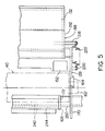
- Figure 5 is a top plan view showing partly a first frame member of the process unit of Figure 4 and various constituent elements mounted on the frame member.
- Figure 6 is a sectional view for illustrating the operation of mounting a rotating drum on the unit frame of the process unit shown in Figure 4.
- Figure 7 is a partly broken-away sectional view for illustrating the state of supporting the rotating drum.
- Figure 8 is a partial sectional view showing a modified example of the process unit in which a second frame member is at an operative position.
- Figure 9 is a partial sectional view showing the process unit of Figure 8 in the state in which the second frame member is held in a non-operative position.
- Figure 10 is a sectional view showing an optical unit and its vicinity in the laser beam printer of Figure 1.
- Figure 11 is a top plan view showing the optical unit in the laser beam printer of Figure 1.
- Figure 12 is a sectional view for illustrating the positional relationship between the optical unit and the process unit in the laser beam printer of Figure 1.
- Figure 13 is a sectional view of the process unit and its vicinity, as viewed from above, in the laser beam printer of Figure 1.
- Figure 14 is a simplified view for illustrating the manner of mounting the process unit.
- Figure 15 is a sectional view for illustrating in a simplified manner a process unit and an optical unit and their neighborhoods in a first modified embodiment of the laser beam printer.
- Figure 16 is a top plan view for illustrating the manner of mounting the process unit in the laser beam printer of Figure 15.
- Figure 17 is a sectional view for illustrating the positional relationship between the optical unit and the process unit in the laser beam printer of Figure 15.
- Figure 18 is a sectional view showing the state in which a receiving section defined in a projecting portion of a unit frame in the laser beam printer of Figure 15 is in engagement with a projecting portion of the optical unit frame.
- Figure 19 is a sectional view showing in a simplified manner a process unit and optical unit and the neighborhoods of these in a second modified embodiment of the laser beam printer.
- Figure 20 is a sectional view showing a third modified embodiment of the laser beam printer in a simplified manner.
- the illustrated laser beam printer has a main body shown by reference numeral 2.
- the main body 2 is provided with a lower section 4 whose left portion 4a in Figures 1 and 2 projects upwardly.
- An opening-closing housing 6 is disposed in the right upper portion of the lower section 4.
- An operating panel 8 is provided in the front surface of the left portion 4a of the lower section 4.
- the housing 6 is mounted on the lower section 4 in the following manner.
- a supporting shaft 14 extending in the front-rear direction (in the direction from left bottom to right top in Figure 1, in the direction perpendicular to the sheet surface in Figure 2, and in the left-right direction in Figure 3) is mounted on the inside of an upper wall 12 of the left portion 4a in the lower section 4.
- a pair of fixing projections 16 (only one of which is shown in Figure 2) are provided in the upper end portion of the housing 6 with a space therebetween in the front-rear direction.
- a linking member 18 is attached to each of the fixing projections 16.
- the linking member 18 is nearly U-shaped as a whole and a partly open, nearly circular hole is formed in its center.
- a pair of protrusions 20 In an intermediate portion are provided a pair of protrusions 20, and by threadably securing a fixing screw 22 to the fixing projections 16 through the protrusion 20, the linking member 18 is attached as is required.
- the opening-closing housing 6 and the lower section 4 of the main body are linked to each other pivotally via the supporting shaft 14 and the linking member 18 by positioning the supporting shaft 14 within the hole of each linking member 18 and then threadingly securing a bolt 24 and a nut 26 through both end portions of the linking member 18.
- a locking means 28 is interposed between the lower section 4 of the main body and the opening-closing housing 6.
- the illustrated locking means 28 is comprised of an engaging member 30 mounted for free pivoting movement between a locked position in the right bottom of the housing 6 (the position shown by a solid line in Figure 2) and a non-locked position (the position shown by a two-dot chain line in Figure 2) and an engaging opening 34 formed in a wall 32 of the lower section 4 of the main body.
- an engaging member 30 mounted for free pivoting movement between a locked position in the right bottom of the housing 6 (the position shown by a solid line in Figure 2) and a non-locked position (the position shown by a two-dot chain line in Figure 2) and an engaging opening 34 formed in a wall 32 of the lower section 4 of the main body.
- the engaging member 30 When the engaging member 30 is at the locked position, its claw portion engages the engaging opening 34.
- the claw portion of the engaging member 30 engages the engaging opening 34 to lock the housing 6 releasably at the closed position.
- a process unit shown generally at 36 is mounted on the main body 2.
- the illustrated process unit 36 has a process unit frame 38 on which a rotating drum 40 constituting an image-bearing means is mounted rotatably.
- An electrographic photosensitive plate is disposed on the peripheral surface of the rotating drum 40.
- Around the rotating drum 40 rotating in the direction shown by an arrow 42 are disposed a charging corona discharger 44, a developing device 46, a transfer corona discharger 48 and a cleaning device 50.
- the charging corona discharger 44, the developing device 46 and the cleaning device 50 are mounted on the unit frame 38.
- the process unit 36 will be described in more detail hereinafter.
- the optical unit 56 includes a laser beam source 58 ( Figure 11), a rotating polygon mirror 60, an f ⁇ lens 62, a first reflecting mirror 64, a second reflecting mirror 66 and a cylindrical lens 68.
- the laser beam source 58 irradiates a laser beam based on image information outputted from, for example, a computer toward the polygon mirror 60.
- the laser beam reflected from the rotating polygon mirror 60 passes through the f ⁇ lens 62 and reaches the first reflecting mirror 64, is reflected by the first and second reflecting mirrors 64 and 66, further passes through the cylindrical lens 68, and is projected onto the surface of the rotating drum 40 in a projecting zone 70 as shown by one-dot chain line.
- a conveying mechanism shown generally at 72 is disposed in the lower portion of the main body 2 and below the process unit 36.
- the conveying mechanism 72 defines a conveying passage for conveying a sheet material such as a recording paper through a transfer zone, and includes a conveyor roller pair 76, a guide plate 78, a guide plate 80, a fixing roller pair 82 and a lower discharge roller pair 84.
- the upstream end of the conveying passage is bifurcated. One part extends in a straight line to the right in Figure 3 and a hand-insertion feed means 86 is provided in its upstream end.
- the other part curves and extends downwardly, and an automatic feed means 88 is provided at its upstream end (specifically, below the conveying mechanism 72 and at the bottom part of the lower section 4).
- the hand-insertion feed means 86 includes a table 90 which is free to pivot between a feed position shown in Figure 3 and a storage position (not shown) displaced upwardly. When the hand-insertion feed means 86 is to be utilized, the table 90 is held at the feed position.
- the illustrated automatic feed means 88 includes a cassette 98 in which sheet materials are stacked.
- the cassette 98 is detachably loaded into a cassette receiving section 102 defined in the lower section 4 of the main body through an opening 100 formed in the front surface (left surface in Figure 3) of the lower section 4 (see Figures 1 and 2 also).
- a feed roller 104 is disposed above the cassette-receiving section 102. By rotating the feed roller 104 in the direction shown by an arrow 106, the sheet materials in the cassette 98 are delivered one by one. The delivered sheet material is guided by a guiding protrusion 110 provided in an upstanding wall portion 108 of the lower section 4 of the main body and the above guiding protrusion 96 and conducted to the conveyor roller pair 76.
- a rectangular opening-closing portion 112 in the front surface of the housing 6 is adapted to be selectively held at a first position shown by a two-dot chain line in Figure 3 and a second position shown by a solid line in Figure 3 (the positions also shown in Figures 1 and 2).
- the opening-closing portion 112 of the housing 6 is at the first position, the sheet material delivered from the lower discharge roller pair 84 is discharged directly out of the housing 6 and received in the inside surface (the upper surface in the state shown by a two-dot chain line) of the opening-closing portion 112.
- the opening-closing portion 112 functions as a first receiving section.
- the sheet material delivered from the lower discharge roller pair 84 is further conveyed upwardly passing between the opening-closing portion 112 and a part 113 of the housing 6 and by the action of an upper discharge roller pair 114, is discharged into a receiving section 116 (functioning as a second receiving section) defined in the upper surface of the housing 6.
- the receiving section 116 is defined by an upwardly inclined wall 118 in the housing 6, and on the upper end portion of the upwardly inclined wall 118 is mounted an auxiliary receiving member 122 which is free to pivot between a receiving position shown in Figures 1 to 3 and a storage position pivoted about 180 degrees from the receiving position in the direction shown by an arrow 120.
- the charging corona discharger 44 charges the photosensitive material of the rotating drum 40. Then, a laser beam from the laser beam source 58 of the optical unit 56 is projected onto the photosensitive material in the projecting zone 70. Consequently, a latent electrostatic image corresponding to the image information is formed on the surface of the photosensitive material by the action of a latent electrostatic image forming means composed of the charging corona discharger 44 and the optical unit 56. Then, a toner is applied to the latent electrostatic image on the photosensitive material by the action of the developing device 46 to develop it into a toner image.
- a sheet material fed into the conveying passage from the hand insertion feed means 86 or the automatic feed means 88 is brought into contact with the photosensitive material in the transfer zone, and by the action of the transfer corona discharger 48, the toner image on the photosensitive material is transferred to the sheet material.
- the sheet material having the toner image transferred thereto is peeled from the rotating drum 40, and the toner image is fixed to the surface of the sheet material by the action of the fixing roller pair 82.
- the sheet material having the fixed toner image is conveyed to the lower discharge roller pair 84, and when the opening-closing portion 112 is at the first position, directly discharged onto the opening-closing portion 112.
- the sheet material is discharged with its image-bearing surface directed upwardly.
- the opening-closing portion 112 is at the second position, the sheet material conveyed to the lower discharge roller pair 84 is further conveyed upwardly, and discharged into the receiving section 116 by the action of the upper discharge roller pair 114.
- the sheet material is discharged with the image-bearing surface directed downwardly, as can be seen from Figure 1, and no page arrangement of the discharged sheet materials is necessary.
- the rotating drum 40 continues to rotate, and by the action of the cleaning device 50, the residual toner is removed from the surface of the photosensitive material.
- the illustrated process unit 38 is provided with a first frame member 124 disposed in the right portion in Figure 4, and a second frame member 126 disposed in the left portion in Figure 4.
- the first frame member 124 has a pair of end walls 128 and 130 (Figure 5 shows one end wall 128 and Figures 3 and 4, the other end wall 130) spaced from each other in a direction (the vertical direction in Figure 5) perpendicular to the sheet surface in Figures 3 and 4, and an upper wall 132 is provided between the end walls 128 and 130.
- the rotating drum 40 and the developing device 46 are mounted on the first frame member 124, and a toner recovery chamber 134 in the cleaning device 50 is provided.
- the second frame member 126 has a pair of end walls 136 and 138 ( Figure 7 shows one end wall 136, and Figures 3 and 4, the other end wall 138) spaced from each other in a direction perpendicular to the sheet surface in Figures 3 and 4, and an upper wall 140 is disposed between the end walls 136 and 138.
- the charging corona discharger 44 and the toner removing means 142 in the cleaning device 50 are mounted on the second frame member 126.
- the first frame member 124 and the second frame member 126 are mounted so as to be free to pivot in the directions shown by arrows 144 and 146 ( Figure 6).
- the end walls 136 and 138 in the second frame member 126 are positioned outwardly of the end walls 128 and 130 in the first frame member 124, and the left end portion of the end wall 128 in the first frame member 124 is pivotally connected to a lower projecting portion 136a formed in the end wall 136 of the second frame member 126 via a linking pin (not shown).
- the left end portion of the end wall 130 of the first frame member 124 is pivotally connected to a lower projecting portion 138a formed in the end wall 138 of the second frame member 126 via a linking pin 148.
- an operative position locking means 150 is provided which releasably locks the second frame member 126 at the operative position.
- the locking means 150 is comprised of a protruding portion 152 provided in the left end portion in Figures 4 and 5 of the upper wall 132 of the first frame member 124 and a receiving portion 156 defined in an elastically deformable portion 154 provided in the right end portion in Figure 4 of the upper wall 140 of the second frame member 126.
- the protruding portion 152 of the upper wall 132 is detachably received by the receiving portion 156 in the elastically deformable portion 154, and thus locked in the operative position by the locking means 150, and this locked state is maintained by the recovering force of the elastically deformable portion 154.
- the rotating drum 40 is mounted on the unit frame 38 in the following manner.
- the rotating drum 40 has a cylindrical portion 158 having a photosensitive material disposed on its peripheral surface and shaft portion 160 provided at opposite end surfaces of the cylindrical portion 158.
- a bearing member 162 is mounted on each of the shaft portions 160.
- receiving portions 164 and 166 (Figure 5 shows one receiving portion 164, and Figures 4 and 6, the other receiving portion 166) are provided nearly centrally in the left-right direction in Figures 4 and 5 in the end walls 128 and 130, respectively, of the first frame member 124.
- the receiving portions 164 and 166 are nearly circular with an open top, and are defined by the upper edges of the end walls 128 and 130.
- a first guide portion 168 and a second guide portion 170 are provided in the first frame member 124 to facilitate the mounting of the rotating drum.
- inner walls 172 and 174 (Figure 5 shows one inner wall 172, and Figures 4 and 6, the other inner wall 174) are disposed inwardly of the left portions of the end walls 128 and 130 respectively, of the first frame member 124. These inner walls 172 and 174 function as the first guide portion 168.
- the inner walls 172 and 174 are disposed corresponding to both end parts of the cylindrical portion 158 of the rotating drum 40 on which no photosensitive material substantially exists, or an image is not substantially formed even when the photosensitive material exists.
- the upper surfaces of these inner walls are comparatively greatly inclined downwardly in a straight line toward the receiving portions 164 and 166.
- the left portions of the end walls 128 and 130 function as the second guide portion 170.
- the left portions of the end walls 128 and 130 are positioned correspondingly to the shaft portions 160 of the rotating drum 40 (in the illustrated embodiment, the bearing members 162 mounted on them), and their upper surfaces are comparatively gently inclined downwardly in a straight line from the left end of the unit frame 38 to the receiving portions 164 and 166.
- both end parts of the cylindrical portion 158 of the rotating drum 40 are first positioned on the first guide member 168 (the inner walls 172 and 174) as shown in Figure 6, and moved downwardly to the lower end portion of the first guide portion 168 along the guiding surface of the first guide portion 168.
- the rotating drum 40 is allowed to fall further downwardly and its shaft portions 160 (the bearing members 162) are positioned on the second guide portion 170 (the left portions of the end walls 128 and 130) and the rotating drum is moved slightly downwardly along the guiding surface of the second guide portion 170. Thereafter, the shaft portions 160 are allowed to fall into the receiving portions 164 and 166 defined by the end walls 128 and 130.
- the shaft portions 160 of the rotating drum 40 are detachably received in the receiving portions 164 and 166 of the end walls 128 and 130.
- it is lifted in such a manner as to detach the shaft portions 160 from the receiving portions 164 and 166.
- the receiving portions 164 and 166 it is preferred to employ the structure shown in Figure 7. Firstly, it is preferred to provide an enlarged portion 178 in the upper parts of the receiving portions 164 and 166 (for the receiving portion 166, see Figures 4 and 6), more specifically in the upper side of that part of the receiving portions 164 and 166 which make contact with the bearing members 162, by forming a depressed portion, for example.
- the introducing parts of the receiving portions 164 and 166 become slightly large, and the shaft portions 160 of the rotating drum 40 can be easily mounted on, and detached from, the receiving portions 164 and 166.
- the receiving portions 164 and 166 are constructed such that they fully support the force acting on the rotating drum 40.
- the direction of an acting force F on the rotating drum 40 is displaced by an angle of 90 + ⁇ which is the sum of 90 degrees displaced clockwise from an axis line P connecting the center of rotation of the driving gear 182 and the center of rotation of the rotating drum 40 and the pressure angle ⁇ of the gear 180. If the pressure angle ⁇ is 20 degrees, this direction is the one shown in Figure 5.
- the receiving portions 164 and 166 extends clockwise in an arcuate shape from right bottom in the horizontal direction to left top in the horizontal direction and make contact with the bearing members 162 to support the rotating drum 40, as shown in Figure 7.
- the arcuate parts of the receiving portions 164 and 166 extend further upwardly beyond the acting direction of the acting force F, and the acting force F exerted on the rotating drum 40 via the driving gear 182 and the gear 180 is transmitted to the end walls 128 and 130 via the bearing members 162 and the receiving portions 164 and 166. Consequently, the receiving portions 164 and 166 accurately support the shaft portions 160.
- the developing device 46 is mounted on the unit frame 38 in the following manner.
- the illustrated developing device 46 includes a main body 188 having a lower housing 190 and an upper housing 192.
- An opening is defined in the lower part of the left surface (that surface which faces the rotating drum 40) of the main body 188 of the developing device, and a magnetic brush mechanism 194 is disposed in the opening portion.
- the magnetic brush mechanism 194 is comprised of a hollow sleeve 198 to be rotated in the direction shown by an arrow 196 and a stationary permanent magnet 200 disposed within the hollow sleeve 198, and holds a developer composed of a toner magnetically and applies it to the surface of the photosensitive material on the rotating drum 40.
- a doctor blade 202 which may be formed of, for example, a thin plastic film is disposed in the opening portion.
- the doctor blade 202 extends downwardly from a securing member 204 fixed to the upper housing 192 and its free end portion is kept in press contact with the peripheral surface of the hollow sleeve 198.
- the doctor blade 202 acts to remove the excess of the developer held on the magnetic brush mechanism 194.
- a toner is held in a toner holding chamber 206 defined by the lower housing 190, the upper housing 192 and the doctor blade 202, and an agitating feed roller 208 is disposed at the bottom of the toner holding chamber 206.
- the agitating feed roller 208 is rotated in the direction shown by an arrow 210 and mixes a toner in the toner holding chamber 206 with a toner which is recovered in a toner recovery chamber 134 and fed into the toner holding chamber 206 by the action of a toner transfer means (to be described) with agitation, and feeds the mixed toner to the magnetic brush mechanism 194.
- Supporting pins 216 (only one of which is shown in Figures 4 and 6) are fixed to the left upper parts of walls 212 and 214, and by attaching the supporting pins 216 pivotally to the inside surfaces of the end walls 128 and 130 of the unit frame 38, the developing device 46 is mounted on the unit frame 38.
- Pins 218 are fixed respectively to the lower parts of the outside surfaces of the end walls 212 and 214 in the main body 188 of the developing device, and corresponding to these pins 218, pins 220 are fixed also to the outside surfaces of the end walls 128 and 130 in the unit frame 38.
- Biasing coil springs 222 (one of them is shown in Figure 5, and the other, in Figures 4 and 6) are interposed between the pins 218 and pins 220 respectively.
- both end parts of its cylindrical portion 158 acts on a roll 224 ( Figure 7) mounted rotatably on the shaft portion of the hollow sleeve 198 in the magnetic brush mechanism 194 to pivot the developing device 46 slightly counterclockwise against the biasing force of the biasing coil springs 222.
- the developing device 46 is held at the angular position shown in Figure 4 and by a solid line in Figure 6.
- the developing device 46 is elastically biased in a direction approaching the rotating drum 40 with the supporting pins 216 as a center.
- the distance between the peripheral surface of the cylindrical portion 158 of the rotating drum 40 and the peripheral surface of the hollow sleeve 198 is adjusted to a fixed value determined by the roll 224.
- the cleaning device 50 is mounted on the unit frame 38 in the following manner.
- an elastic blade 226 constituting a toner removing means 142 is mounted on the second frame member 126.
- linking portions 230 (only one of which is shown in Figures 4 and 6) provided at both ends of a swinging support member 228 are pivotally linked to the end walls 128 and 130 of the first frame member 124 via linking pins 148.
- a blade securing member 232 is fixed to the swinging support member 228, and the elastic blade 226 is fixed to the free end of the blade securing member 232 by an adhesive or otherwise.
- a pair of upper protrusions 234 spaced from each other in a direction perpendicular to the sheet surface in Figures 4 and 6 are provided integrally.
- a biasing coil spring 238 is interposed between each of the upper protrusions 234 and a linking wall 236 connected between the end walls 136 and 138 of the second frame member 126.
- the biasing coil spring 238 biases the swinging support member 228, and therefore the elastic blade 226, clockwise in Figures 4 and 6 about the linking pin 148 as a center.
- Suspending pieces 240 which can abut with the upper protrusions are provided at predetermined sites in the inner surface of the upper wall 140 of the second frame member 126.
- the swinging support member 228 can pivot relative to the second frame member 126 between an angular position at which its left end abuts with the linking wall 236 and an angular position at which the upper protrusions abut with the suspending pieces 240 of the upper wall 140 in Figures 4 and 6.
- the swinging support member 228 is held by the action of the biasing coil spring 238 at the angular position at which the upper protrusions 234 abut with the suspending pieces 240.
- the toner recovery chamber 134 for recovering the toner removed from the rotating drum 40 is defined between the inner walls 172 and 174 of the first frame member 124.
- a nearly arcuate curved linking wall 242 is provided between the inner walls 172 and 174, and the toner recovery chamber 134 is defined by the inner surface of the linking wall 242.
- a film-like sealing member 244 extending toward the rotating drum 40 is provided at one end (upper end) of the linking wall 242, and a film-like sealing member 246 extending toward the rotating drum 40 and contacting or approaching the peripheral surface of the drum 40, at the other end portion (lower end portion).
- the sealing member 246 prevents falling of the toner through the space between the rotating drum 40 and the linking wall 246, and conducts the toner removed from the rotating drum 40 to the toner recovery chamber 134.
- a helical toner transfer member 248 extends from the toner recovery chamber 134 to the toner holding chamber 206 of the developing device 46, and feeds the toner recovered in the toner recovery chamber 134 to the toner holding chamber 206 through a hollow cylindrical member 250 (see Figure 3 also).
- the swinging support member 228 is likewise pivoted, and the elastic blade 226 moves in a direction away from the rotating drum 40 and leaves the surface of the photosensitive material relatively greatly (see Figure 6).
- the second frame member 126 is pivoted in the closing direction shown by arrow 144 ( Figure 6) and held at the operative position, the forward end portion of the elastic blade 226 acts on the surface of the photosensitive material on the rotating drum 40 and is kept in press contact with its surface at a predetermined pressure by the biasing force of the biasing coil spring 238.
- the biasing coil spring 238 is slightly contracted by the abutting of the elastic blade 226 with the surface of the photosensitive material, and the upper protrusions 234 of the swinging support member 228 are apart from the suspending pieces 240 of the upper wall 140, as shown in Figure 4.
- the operation of detaching the rotating drum 40 starts with the detachment of the process unit 36 from the main body 2 of the machine in the manner to be described and the placing of the detached process unit 36 on the surface S ( Figure 6) such as a table surface.
- the elastically deformable portion 154 of the second frame member 126 is slightly deformed elastically and the engagement between the protruding portion 152 in the first frame member 124 with the receiving portion 156 defined in the elastically deformable portion 154 is cancelled.
- the second frame member 126 is pivoted in the opening direction shown by arrow 146 and brought to the position shown in Figure 6 (held at this position by the abutting of the left end of the second frame member 126 with the surface S.
- the swinging support member 228 pivots likewise, and the elastic blade 226 moves in a direction away from the rotating drum 40, whereby the elastic blade 226 comes out of contact with the photosensitive material of the rotating drum 40.
- the second frame member 126 moves substantially to the left of the first frame member 124 whereby the top of the rotating drum 40, the top of the left portions of the end walls 128 and 130 (the second guide portion 170) and the top of the inside walls 172 and 174 (the first guide portion 168) are open to view, and the first guide portion 168 and the second guide portion 170 are exposed outside.
- the rotating drum 40 is lifted and the bearing member 162 is detached from the receiving portions 164 and 166 defined in the end walls 128 and 130.
- the rotating drum 40 can thus be detached easily without injuring the photosensitive material on its surface because its top is relatively greatly open to view and the elastic blade 226 is spaced from the rotating drum 40.
- both end portions of its cylindrical portion 158 are positioned from above onto the first guide portion 168, and moved as shown by the two-dot chain line in Figure 6 along the first guide portion 168. Then, the bearing members 162 on the shaft portions 160 are positioned in the second guide portion 170 as shown by the broken line in Figure 6 and slightly moved along it, and then allowed to fall into the receiving portions 164 and 166. As a result, the shaft portions 160 of the rotating drum 40 are detachably received by the receiving portions 164 and 166.
- the rotating drum 40 can be easily mounted without injuring the photosensitive material because the elastic blade 226 is in a retracted position. Furthermore, it is sufficient at the time of mounting to move the cylindrical portion 158 of the rotating drum 40 along the first guide portion 168 and then move the bearing members 162 in its shaft portions 160 along the second guide portion 170. Thus, the rotating drum 40 can be mounted easily without injuring the photosensitive material.
- the second frame member 126 When thereafter, the second frame member 126 is pivoted in the closing direction shown by arrow 144 and held at the operative position shown in Figure 4, the protruding portion 152 of the upper wall 132 is received in the receiving portion 156 of the elastically deformable portion 154 and thus the second frame member 126 is held at the operative position.
- the forward end portion of the elastic blade 226 is brought into press-contact with the surface of the photosensitive material in the rotating drum 40 by the action of the biasing coil spring 238, and the toner on the photosensitive material of the rotating drum 40 is removed by the action of the elastic blade 226.
- the second frame member is adapted to be releasably locked at the operative position. If desired, it is also possible to construct the second frame member such that it can also be releasably locked at a non-operative position displaced slightly in the opening direction from the operative position.
- a non-operative position locking means 254' is provided in addition to the operative position locking means 158'.
- the operative position locking means 150' is provided with a receiving portion 156' defined in the elastic deformable portion 154' of the second frame member 126', and by holding the second frame member 126' at the operative position shown in Figure 8, the protruding portion 152' provided in the upper wall 132' of the first frame member 124' is received detachably in the receiving portion 156'.
- the elastic blade 226' acts on the surface of the photosensitive material on the rotating drum 40', and its forward end portion is brought into press-contact with the surface of the photosensitive material by the action of the biasing coil spring 238'.
- the non-operative position locking means 254' is provided with a receiving portion 256' defined in the forward end portion of the elastically deformable portion 154' (further forwardly of the site at which the receiving portion 156' is defined), and by pivoting the second frame member 126' slightly in the opening direction shown by arrow 146' from the operative position, the protruding portion 152' of the first frame member 124' is detached from the receiving portion 156' and received detachably in the receiving portion 256', as shown in Figure 9.
- the non-operative position locking means 254' is in the locking state, and the second frame member 126' is held at the non-operative position shown in Figure 9.
- the elastic blade 226' moves in a direction away from the rotating drum 40' and its forward end portion does not substantially act on the surface of the photosensitive material but is slightly apart from the surface because the second frame member 126' is slightly pivoted in the opening direction.
- the operative position locking means 150' and the non-operative position locking means 254' may be provided separately for exclusive use.
- the optical unit 56 is provided with a box-like optical unit frame 260, and the optical means 69 is disposed within the optical unit frame 260.
- the optical unit frame 260 is composed of various walls 262, 264, 266, 268, 270, 272 and 274 to do fine a substantially sealed space.
- the laser beam source 58 is mounted on the wall 264, and the rotating polygon mirror 60, the f ⁇ lens 62, the first reflecting mirror 64, the second reflecting mirror 66 and the cylindrical lens 68 are mounted on the optical unit frame 260.
- parts 272a and 274a of the walls 272 and 274 project downwardly, and an elongate rectangular projecting opening 276 is defined by these projecting portions 272a and 274a.
- the opening 276 is covered with a transparent glass sheet 278, and a laser beam from the laser beam source 58 is projected onto the surface of the photosensitive material of the rotating drum 40 through the transparent glass sheet 278.
- the optical unit frame 260 is mounted on the inner surface of the upwardly inclined wall 118 of the housing 6 in the following manner.
- three inwardly projecting boss portions 282 are formed integrally in the inner surface of the upwardly inclined wall 118 of the housing 6 in the illustrated embodiment.
- one boss portion 282 is formed in the right end portion in Figure 12 of the upper wall 282, and two boss portions 282, in the left end portion in Figure 10 of the upwardly inclined wall 118 (the boss portions are spaced from each other in a direction perpendicular to the sheet surface in Figure 10). Internally threaded holes are formed in these boss portions 282.
- protrusions 284 protruding outwardly are formed in the peripheral surface of each boss portion 282, and a stepped part is provided in each of the protrusions 284.
- supporting outwardly projecting portions 286 and 288 are formed integrally in the walls 266 and 268 of the optical unit frame 260.
- One hole 290 corresponding to the boss portion 282 is formed in one supporting projecting portion 286, and two holes 292 corresponding to the two boss portions 282, in the other supporting projecting portion 288.
- the optical unit frame 260 is mounted on the inner surface of the upwardly inclined wall 118 by threadedly securing fixing screws 294 to the boss portions 282 of the upwardly inclined wall 118 throughout the holes 290 and 292 formed in the optical unit frame 260.
- the optical unit frame 260 is free to move in the vertical direction in Figures 10 and 12, or in other words, in a direction moving toward and away from the process unit 36 between a position at which the supporting projecting portions 286 and 288 abut with the forward ends of the boss portions 282 and a position at which they abut with the head parts of the fixing screws 294 secured to the boss portions 282.
- the outside diameter of the shaft portion of each fixing screw 294 is smaller than the inside diameter of the hole 290 or 292 formed in the optical unit frame 260.
- the optical unit frame 260 can move in the left-right direction in Figure 10 (the direction perpendicular to the sheet surface in Figure 12) and in a direction perpendicular to the sheet surface in Figure 10 (the left-right direction in Figure 12), or in other words in a horizontal direction substantially parallel to the process unit 36, within a range in which the shaft portions of the fixing screws 194 can move within the corresponding holes 190 and 192.
- Biasing coil springs 296 constituting a biasing means are also provided in the optical unit frame 260.
- the biasing coil springs 296 are fitted over the boss portions 282 and interposed between the stepped parts of the protrusions 284 and the supporting projecting portions 286 and 288. These biasing coil springs 296 elastically bias the optical unit frame 260 downwardly in Figures 10 and 12, or in other words, in a direction approaching the process unit 36.
- the optical unit frame 260 is usually (for example, when the housing 6 is held at the open position) held at a predetermined position by the abutting of the supporting projecting portions 286 and 288 with the head parts of the fixing screws 294.
- a charge eliminating lamp (not shown) is mounted on the optical unit frame 260.
- a lamp housing 298 is mounted by a fixing screw 300 to the under surface of the supporting protruding portion 288 of the optical unit frame 260, and the charge eliminating lamp is disposed in the lamp housing 298.
- the charge eliminating lamp illuminates the rotating drum 40 through a charge eliminating opening 304 ( Figures 10 and 13) formed in the upper wall 140 of the second frame member 126 in the process unit 36 to erase the residual charge on the photosensitive material.
- the process unit 36 is mounted detachably on the lower section 4 of the main body 2 of the machine in the following manner.
- a pair of vertical base plates 310 and 312 are disposed in spaced-apart relationship in the aforesaid crosswise direction in the lower section 4 of the main body.
- the vertical base plate 310 is divided in the front-rear direction (the left-right direction in Figure 13), and an inwardly projecting supporting pin 314 is set up in the inner surface of its one side 310a.
- An inwardly projecting supporting pin 316 is also set up in the inner surface of its other side 310b.
- a pair of supporting pins 318 and 320 projecting inwardly and spaced from each other in the front-rear direction are also set up in the inside inner surface of the vertical base plate 312.
- a support projecting portion 322 corresponding to the supporting pin 314 is provided in the outer surface of the end wall 136 of the second frame member 126 of the process unit 36, and a support projecting portion 326 corresponding to supporting pin 318 is provided in the outer surface of the other end wall 138.
- a support projecting portion 324 corresponding to the supporting pin 316 is provided in the outer surface of the end wall 128 of the first frame member 124 of the process unit 36, and a support projecting portion 328 corresponding to the supporting pin 320, in the outer surface of the other end wall 130.
- the under surfaces of the support projecting portions 322 and 326 are substantially flat, and a pair of upwardly projecting knob protrusions 330 are provided in the upper surface of these support projection portions.
- Arcuate receiving portions are defined in the under surfaces of the support projecting portions 324 and 328.
- the unit frame 38 is detachably mounted across the vertical base plates 310 and 312 by placing it on the supporting pins 314, 316, 318, and 320 from above, or more specifically, positioning the receiving portions defined in the support projecting portions 324 and 328 (at one end portion of the unit frame 38) in the supporting pins 316 and 320 (constituting one supporting means) and at the same time, positioning the support projecting portions 322 and 326 at the other end portion in the supporting pins 314 and 318 (constituting the other supporting means).
- an elastic piece 332 such as a plate spring is provided at that site of the first frame member 124 of the unit frame 38 on which the tip of the supporting pin 320 acts. Accordingly, in the above mounted state, the elastic piece 332 acts on the unit frame 38 to bias it elastically downwardly.
- the tip of the supporting pin 316 abuts with the end wall 128 of the first frame member 124, and the unit frame 38 is held at the position shown by a solid line in Figure 13. Furthermore, in this mounted state, the unit frame 38 is free to pivot about the supporting pins 316 and 320 (constituting an axis of the center of pivoting) as a center. Hence, by holding the knob portions 330 of the support projecting portions 332 and/or 326 and lifting them, the unit frame 38 can be pivoted in the direction shown by an arrow 334 to the position shown by a two-dot chain line in Figure 14.
- the illustrated positioning means is comprised of a combination of a positioning projection and a receiving portion for detachably receiving the positioning projection.
- the positioning projection is comprised of a cylindrical positioning pin 346 set up integrally in the under surface of the wall 272 of the optical unit frame 260
- the receiving portion is comprised of a receiving hole 342 defined by a circular protrusion 338 provided integrally on the upper surface of the upper wall 140 of the second frame member 126 in the process unit 36.
- the receiving hole 342 is of a circular shape having an inside diameter corresponding to the outside diameter of the positioning pin 346.
- the receiving hole 342 defining the receiving portion is provided in the neighborhood of an exposure opening 347 defined between the upper wall 132 of the first frame member 124 and the upper wall 140 of the second frame member 126 as shown in Figure 13. This arrangement enables the projecting opening 226 in the optical unit 56 and the exposure opening 347 to be maintained at a predetermined positional relationship more accurately.
- the rotation hampering means is comprised of a rotation hampering protrusion and a receiving portion for detachably receiving the rotation hampering protrusion.
- the rotation hampering protrusion is comprised of a cylindrical rotation hampering pin 348 integrally provided in the under surface of the wall 272 of the optical unit frame 260
- the receiving portion is comprised of an elongate receiving hole 344 defined in the protrusion 340 formed integrally on the upper surface of the upper wall 140 of the second frame member 126 in the process unit 36.
- the receiving hole 344 has a width corresponding to the outside diameter of the rotation hampering pin 348, and extends in a direction substantially perpendicular to the axis of the center of pivoting of the housing 6 (left-right direction in Figure 12).
- the rotation hampering pin 348 When the housing 6 is held at the closed position in the manner to be described, the rotation hampering pin 348 is positioned in place in the elongate receiving hole 344. As a result, the relative pivoting movement of the process unit frame 38 and the optical unit frame 260 about the positioning pin 346 as a center can be accurately hampered.
- the positioning means it is possible to provide the positioning protrusion in the process unit frame 38 and the receiving portion in the optical unit 260 contrary to the above-described feature.
- the rotation hampering means too, it is possible to provide the rotation hampering protrusion in the process unit frame 38 and the receiving portion in the optical unit frame 260 contrary to the above feature.
- three actuating pieces 350 are provided in the optical unit frame 260 in order to maintain a predetermined vertical distance between the process unit frame 38 and the optical unit frame 260.
- One actuating piece 350 is nearly triangular, and is provided at the end portion of the wall 274. It acts on the right end portion in Figure 10 of the upper wall 132 of the first frame member 124.
- the other two actuating pieces 350 are cylindrical pins and are provided on the supporting projection 288 in spaced-apart relationship in the lateral direction (the left-right direction in Figure 12 and in a direction perpendicular to the sheet surface in Figure 10). They act on the left end portion in Figure 10 of the upper wall 140 of the second frame member 126.
- the actuating pieces 350 act on the process unit 36, and the distance between the process unit frame 38 and the optical unit frame 260 is maintained at a predetermined value by the action of these actuating pieces 350.
- the distance between the optical unit frame 260 and the process unit frame 38 can be accurately maintained at a desired value.
- the opening-closing housing 6 is first opened. Specifically, the locking in the locking means 28 is released, and the housing 6 is pivoted in the direction of arrow 35.
- the engaging member 30 in the locking means 28 is held at the non-locking position shown by the two-dot chain line in Figure 2, the engaging member 30 is disengaged from the engaging opening 34 formed in the lower section 4 of the main body.
- the housing 6 is lifted thereafter, the housing 6 pivots in the direction of arrow 35 about the supporting shaft 14 as a center and held at the open position shown by the two-dot chain line in Figure 2.
- the housing 6 is held at the open position, the top of the process unit 36 is open to view. Consequently, part of the conveying passage is opened, and the process unit 36 is in condition for detachment.
- part of the conveying passage (specifically that part of the conveying passage which is below the rotating drum 40) is opened by holding the knob portions 330 of the support portions 322 (and/or 326) provided in the unit frame 38 and lifting them.
- the unit frame 38 is pivoted in the direction of arrow 334 ( Figure 14) about the supporting pins 316 and 320 as a center.
- part of the conveying passage is opened as is required.
- the unit frame 38 is taken out through the space formed by holding the housing 6 in the open position.
- the support portions 322, 324, 326 and 328 are detached respectively from the supporting pins 314, 316, 318 and 320, and the gear 180 is disconnected from the driving gear 182 ( Figure 7).
- the process unit 36 can be detached as is required.
- the unit frame 38 is positioned on the supporting pins 314, 316, 318 and 320 through the aforesaid space while the housing 6 is held at the open position. Consequently, as shown in Figure 13 and by a solid line in Figure 14, the support portions 322, 324, 326 and 328 provided in the unit frame 38 are positioned respectively on the corresponding supporting pins 314, 316, 318 and 320, whereby the process unit 36 is detachably mounted on the lower section 4 of the main body.
- the housing 6 is pivoted in a direction opposite to the direction of arrow 35 from the open position and held at the closed position shown in Figures 1 and 3 and by the solid line in Figure 2.
- the engaging member 30 engages the engaging opening 34, and the housing 6 is held releasably at the closed position by the action of the locking means 28.
- the positioning pin 346 and the rotation hampering pin 348 provided in the optical unit frame 260 are positioned in the receiving portion (the receiving hole 342) and the receiving portion (the receiving hole 344) defined in the unit frame 38 mounted across the vertical base plates 310 and 312 ( Figure 13) as shown in Figures 10 and 12.
- the outside diameter of the positioning pin 346 is substantially equal to the inside diameter of the receiving hole 342
- the specific sites of the unit frame 38 and the optical unit frame 260 (in the illustrated embodiment, that site of the optical unit frame 260 which is near the projecting opening 276 and that site of the unit frame 38 which is near the exposure opening 347) are kept in alignment vertically with each other.
- the outside diameter of the rotation hampering pin 348 is substantially equal to the width of the receiving portion (receiving hole 344). The relative turning of the optical unit frame 260 about the positioning pin 346 as a center with respect to the unit frame 38 can be hampered. As a result, the optical unit 56 is positioned as is required above the process unit 36.
- the receiving portion 116 and the upper inclined wall 118 of the housing 6 are positioned above the optical unit 56, and the process unit 36 and the optical unit 56 are maintained accurately in a predetermined positional relationship via the positioning means and the rotation hampering means.
- the actuating pieces 350 formed in the optical unit frame 260 act on the upper surface of the unit frame 38 (one actuating piece 350 acting on the upper wall 132 of the first frame member 124, and the two actuating pieces 350, on the upper wall 140 of the second frame member 126), and the optical unit frame 260 is slightly elevated against the biasing force of the biasing coil spring 296 with respect to the unit frame 38, as shown in Figures 10 and 12.
- the optical unit frame 260 is maintained at a predetermined distance from the unit frame 38 by the action of the actuating pieces 350 and elastically pressed and held by the action of the biasing coil spring 296.
- the vertical distance between the unit frame 38 and the optical unit frame 260 is accurately maintained at a predetermined value.
- the upwardly inclined wall 118 (the site defining the receiving portion 166) of the housing 6 extends upwardly at a first angle to the horizontal from left to right in Figures 3 and 10, that is, downstream in the discharging direction of the sheet material.
- a laser beam from the laser beam source 58 is reflected by the rotating polygon mirror 60, and then conducted toward left bottom in Figure 3 and downwardly in Figure 11. It is reflected by the first reflecting mirror 64 and reaches the second reflecting mirror 66.
- the longest straight-line portion of the light path of the optical means 69 i.e. the part from the rotating polygon mirror 60 to the first reflecting mirror 64 in the illustrated embodiment, extends substantially parallel along the optical unit frame 260 or in other words, the upwardly inclined wall 118, from right end portion of the optical unit 260 in Figures 3 and 10 to its left end portion in Figures 3 and 10. Accordingly, no wasteful space substantially exists between the upwardly inclined wall 118 of the housing 6 and the optical unit frame 260, and the machine as a whole can be reduced in size. Furthermore, since the main part of the optical path of the optical means 69 is inclined as above described to the horizontal.
- the length in the left-right direction (horizontal) of the optical unit frame 260 in Figures 3 and 10 becomes small. While part of the machine slightly becomes higher, but the size of the machine as a whole in the left-right direction in Figure 3 can be greatly decreased.
- the first angle ⁇ ( Figure 3) can be preset at about 45 degrees in view of the dischargeability of the sheet material received by the receiving portion 116 and the size reduction of the machine as a whole.
- the developing device 46 is disposed as shown in Figure 3, and the toner holding chamber 206 of the developing device 46 is apart from the rotating drum 40 and is positioned outwardly of the magnetic brush mechanism 104.
- the space existing below the right end portion of the optical unit frame 260 in Figures 3 and 10 in which the toner holding chamber 206 exists is relatively high and sufficiently large despite the smaller size of the machine as a whole.
- the above description has been directed mainly to the reduction of the space between the receiving portion 116 into which the sheet material is discharged and the optical means 69.
- the inclination angle (to the horizontal) of the main part of the light path may be a second angle which differs from the first angle.
- the second angle is preferably about 45 degrees which is the same as the first angle when the receiving portion 116 is provided substantially parallel to the main part of the light path in the optical means 69.
- Figures 15 to 18 shows a first modified embodiment of the laser beam printer.
- the positioning means and the rotation hampering means are constructed of a common member.
- a process unit 402 in the first modified embodiment is provided with an ordinary one-piece process unit frame 404 rotating drum 40, a developing device (not shown) and a cleaning device (not shown) are mounted between a pair of end walls 406 and 408 of the unit frame 404 as in the embodiment described above.
- Support projecting portions 412 and 414 constituting a support means are provided at both side ends of the unit frame 404 (the left side end and right side end in Figures 15 and 16).
- the support projecting portions 412 and 414 project to the left and right in Figures 15 and 16, and are provided across the pair of end walls 406 and 408 in the mounting direction of the unit frame 404 shown by an arrow 416.
- a pair of supporting means spaced from each other in the left-right direction in Figures 15 and 16 are provided in the main body 418 of the machine (in the first modified embodiment, it is not constructed of a lower section and an opening-closing housing, and a wall 422 on which the optical unit 420 is mounted cannot be opened and closed).
- the pair of supporting means are comprised of nearly L-shaped supporting rails 424 and 426, and the support projecting portions 412 and 414 are supported on the supporting rails 424 and 426 in a manner to slide freely in the direction shown by arrow 416.
- the process unit 402 can be detachably mounted as described hereinafter on the main body 418 of the machine by opening an openable-closable cover member (not shown: the cover member provided in the right surface in Figures 1 and 2) which is present in front of the sheet surface in Figure 15 (underside in Figure 16) in the main body 418 of the machine.
- an openable-closable cover member not shown: the cover member provided in the right surface in Figures 1 and 2 which is present in front of the sheet surface in Figure 15 (underside in Figure 16) in the main body 418 of the machine.
- an upwardly extending elongate rectangular projecting portion 430 is further provided in the upper wall 428 of the process unit frame 404, and an elongate rectangular exposure opening 432 is defined in the projecting portion 430.
- the opening part of the opening 432 (more specifically, parts defining both side edges of the opening 432) in the projecting portion 430 is inclined downwardly inwardly.
- a downwardly extending projecting portion 436 is provided in a unit frame 434 in the optical unit 420.
- An elongate rectangular projecting opening 438 communicating with the exposure opening 432 is defined in the projecting portion 436.
- the lower end of the projecting portion 436 is inwardly and downwardly inclined, and tapered corresponding to the shape of the opening portion of the projecting portion 430 of the unit frame 404.
- the projecting portion 436 of the optical unit frame 434 acts as a polygonal protrusion
- the opening portion of the exposure opening 432 of the unit frame 404 acts as a polygonal receiving portion.
- the opening parts in the projecting portions 436 and 430 function as the positioning means and rotation hampering means.
- the projecting portion of the optical unit frame 434 also acts as an actuating piece. It will be easily understood by comparing Figures 10 and 12 with Figures 15 and 17 that by this arrangement, the two actuating pieces on the left-hand side in Figure 10 can be omitted.
- the cover member (not shown) is opened and the support projecting portions 412 and 414 of the unit frame 404 are positioned on the supporting rails 424 and 426. Then, a gripping portion 440 ( Figures 15 and 16) of the unit frame 404 is pushed to move the unit frame in the mounting direction shown by arrow 416. As shown in Figure 18, an inclined surface 442 ( Figure 18) inclined downwardly toward the mounting direction shown by arrow 416 is provided in one end portion (the end portion on top in Figure 16 and on the left side in Figure 18) of the projecting portion 430 of the unit frame 404.
- the receiving portions defined in the projecting portions 436 and 430 are elongate and rectangular, they cannot rotate relatively to each other in the engaged state. Accordingly, in the first modified embodiment, the optical unit 420 can move over a predetermined range in the horizontal direction (the left-right direction and the direction perpendicular to the sheet surface in Figure 15) via a fixing screw 446 but when the process unit 402 is moved to the predetermined mounting position as described above, the receiving portions defined in the projecting portions 436 and 430 engage each other to bring the specific site of the optical unit 420 into alignment with the specific site of the process unit 402 and accurately hamper their relative rotation, as is the case with the specific embodiment described hereinabove.
- the optical unit 420 and the process unit 402 are maintained directly in a predetermined positional relationship via the receiving portions defined in the projecting portions 436 and 430 which act as the positioning means and the rotation hampering means. Furthermore, in this mounted state, the actuating piece 448 provided in the optical unit frame 434 acts on the upper surface of an upper wall 450 ( Figure 16), and the undersurface of the projecting portion 436 of the optical unit frame 434 acts on the upper surface of the projecting portion 430 of the unit frame 404. Thus, the optical unit 420 is slightly elevated against the biasing force of the biasing coil spring 444.
- the optical unit frame 434 is maintained at a fixed distance from the unit frame 404 by the action of the actuating piece 448 and the projecting portion 436 which also functions as an actuating piece.
- the optical unit frame 434 is maintained elastically pressed by the action of the biasing coil spring 444, and the vertical distance between the unit frame 404 and the optical unit frame 434 is maintained accurately at a fixed value. Accordingly, in the first modified embodiment, too, the same effect as in the specific embodiment described above can be achieved.
- Figure 19 shows a second modified embodiment of the laser beam printer.
- the process unit is moved in a direction perpendicular to the axial direction of the rotating drum, and mounted on the main body of the machine.
- a process unit 502 is basically of the same structure as in the above-described specific embodiment.
- Support protrusions 508 extending in the left-right direction in Figure 19 are provided in a pair of end walls 506 (only one of which is shown) of the process unit frame 504.
- supporting rails (not shown) constituting a supporting means corresponding to the support protrusions 508 are provided in the main body 510.
- a cover member 512 is provided in that part of the main body 510 which defines the right surface in Figure 19, and the upper end portion of the cover member 512 is pivotally linked to the main body of the machine. Accordingly, the cover member 512 is free to pivot between a closed position shown by a solid line and an open position shown by a two-dot chain line in Figure 19.
- an elongate rectangular projecting portion 514 is provided in the upper wall of the process unit frame 504 as in the first modified embodiment, and a rectangular exposure opening 516 is defined in the projecting portion 514.
- a downwardly extending projecting portion 522 is provided in an optical unit frame 520 of an optical unit 518, and an elongate rectangular projecting opening 524 is defined in the rectangular projecting portion 522.
- the opening part of the exposure opening 516 in the projecting portion 514 acts as a polygonal receiving portion and the front end portion of the projecting portion 522 acts as a polygonal protrusion, and these parts function as a positioning means and a rotation hampering means as in the first modified embodiment.
- the projecting portion 522 of the optical unit frame 520 function also as an actuating piece for maintaining the distance between the optical unit frame 520 and the unit frame 504 constant.
- An inclined surface 528 inclined downwardly in the mounting direction shown by an arrow 526 is formed in one side part (the side part on the downstream side as viewed in the mounting direction shown by arrow 526) of the projecting portion 514 of the unit frame 504. Otherwise, the structure of the second modified embodiment is substantially the same as the specific embodiment described hereinabove.
- the cover member 512 is pivoted in the direction shown by an arrow 530 to the open position shown by the two-dot chain line in Figure 19. Then, the support projecting portions 508 of the unit frame 504 are positioned in the supporting rails (not shown) and the process unit 502 is moved in the mounting direction of arrow 526. As a result of this movement of the process unit 502, the inclined surface 528 formed in the projecting portion 514 of the unit frame 504 acts on the lower end of the projecting portion 522 of the optical unit frame 520 to move the optical unit 518 slightly upwardly against the biasing action of the biasing coil spring 532. This is conductive to the smooth mounting of the process unit 502.
- a projecting piece 534 provided in the unit frame 504 abuts with a stop member 536 of the main body 510 of the machine thereby to hamper accurately the movement of the process unit 502 beyond the mounting position.
- the projecting portion 522 in the optical unit frame 520 is received in the opening part of the projecting portion 514 in the unit frame 504.
- the optical unit 518 is free to move horizontally (in the left-right direction and the direction perpendicular to the sheet surface in Figure 19) over a predetermined range via a fixing screw 538. But when the process unit 502 is held at the predetermined mounting position as described above, the projecting portion 522 engages the receiving portion of the projecting portion 514. As a result, the specific part of the optical unit 518 is brought into alignment with the specific part of the process unit 502 and their relative rotation is hampered.
- the optical unit 518 and the process unit 502 are maintained directly in a predetermined positional relationship via the projecting portion 522 and the receiving portion of the projecting portion 514 acting as the positioning means and rotation hampering means. Furthermore, when the process unit 502 is so mounted, the actuating piece 540 provided in the optical unit frame 520 acts on the upper wall of the unit frame 504 and the undersurface of the projecting portion 522 of the unit frame 520 acts on the upper surface of the projecting portion 514 of the unit frame 504. As a result, the optical unit 518 is slightly elevated against the biasing force of the biasing coil spring 532.
- the optical unit frame 520 is maintained at a fixed distance from the unit frame 504 by the action of the actuating piece 540 and the projecting portion 522 which functions as an actuating piece, and the two are elastically maintained in press contact with each other by the action of the biasing coil spring 532. Accordingly, in the second modified embodiment, the same effect as in the specific embodiment described hereinabove can be achieved.
- the projecting portion (in which the projecting opening is defined) provided in the optical unit frame is adapted to be received in the receiving portion defined in the projecting portion (in which the exposure opening is defined) of the process unit frame.
- the projecting portion of the process unit frame it is possible to adapt the projecting portion of the process unit frame to be received in the projecting portion (the part which defines a receiving portion) of the optical unit frame.
- a polygonal protrusion and a polygonal receiving portion for exclusive use which function as the positioning means and the rotation hampering means may be provided in the optical unit and the process unit.
- Figure 20 shows a third modified embodiment of the laser beam printer.
- the optical unit is mounted on the main body of the machine (its lower section), and a main portion of a conveying means for conveying a sheet material and the process unit are mounted on an opening-closing housing attached to the lower section of the main body so as to be opened or closed.
- the laser beam printer of the third modified embodiment is provided with a main body 602.
- the main body 602 of the machine is comprised of a lower section 603 and an opening-closing housing 606 connected to the right end portion in Figure 20 of the lower section 603 via a shaft member 604.
- the housing 606 is free to pivot between a closed position shown by a solid line in Figure 20 (constituent elements mounted on the main body 602 and constituent elements mounted on the housing 606 are maintained in the positional relationship shown by solid lines) and an open position shown by a two-dot chain line (at which a process unit 608 can be detached from the housing 606 in the manner to be described).
- An optical unit 610 is mounted on the lower section 603 of the main body in the following manner.
- a pair of fixing walls 614 and 616 spaced from each other in the left-right direction in Figure 20 are provided in a bottom wall 612 of the main body 602. At both ends of each of the fixing walls 614 and 616 are provided inwardly projecting abutting protrusions 618 and 620 (only one pair is shown in Figure 20), and inwardly projecting upper abutting protrusions 622 and 624 are formed at the upper ends of the fixing walls 614 and 616.
- the optical unit 610 is mounted between the fixing walls 614 and 616, as shown in Figure 20.
- the optical unit 610 is free to move in the left-right direction in Figure 20 from a position at which it abuts with one fixing wall 614 to a position at which it abuts with the other fixing wall 616, and is also free to move in a direction perpendicular to the sheet surface in Figure 20 from a position at which it abuts with the abutting protrusions 618 and 620 in one of the fixing walls 614 and 616 to a position at which it abuts with the abutting protrusions 618 and 620 of the other fixing wall.
- the optical unit 610 is also free to move vertically from a position at which it abuts with the bottom wall 612 of the main body 602 of the machine to a position at which it abuts with the upper abutting protrusions 622 and 624 of the fixing walls 614 and 616.
- a plurality of biasing coil springs 628 are interposed between the bottom wall 612 and the optical unit frame 626 of the optical unit 610. These biasing coil springs 628 elastically bias the optical unit frame 626 upwardly.
- the process unit 608 is detachably mounted on the housing 606 in the following manner.
- Supporting rails 630 and 632 spaced from each other in the left-right direction in Figure 20 are provided in the housing 606.
- One supporting rail 630 is L-shaped in cross section and in cooperation with a guide plate 633 mounted on the housing 606, defines a guide groove.
- the other supporting rail 632 is rectangular in cross section, and a guide groove is defined in its one side surface (the left side surface in Figure 20).
- the process unit 608 is provided with a process unit frame 634, and support protrusions 636 and 638 corresponding to the supporting rails 630 and 632 are provided in both side ends of the unit frame 634 in the left-right direction in Figure 20.
- three circular protrusions 640 are provided in the upper wall of the optical unit frame 626, and circular receiving holes are defined in the circular protrusions 640.
- Pins 642 corresponding to the circular receiving holes are provided in the bottom wall of the process unit frame 634, and the tip portion of each of the pins 642 is tapered.
- one pin 642 and the receiving holes of the circular protrusion 640 receiving it function as the positioning means.
- the other two pins 642 and the receiving holes of the circular protrusions 640 function as the rotation hampering means.
- the three pins 642 act as actuating pieces for maintaining the distance between the unit frame 634 and the optical unit frame 626 constant.
- the other basic structures of the third modified embodiment are nearly the same as in the specific embodiment described hereinabove.
- the opening-closing housing 606 is pivoted in the direction shown by an arrow 644 to the open position shown by the two-dot chain line. Then, the support protrusions 636 and 638 of the unit frame 634 are positioned in the guide grooves of the supporting rails 630 and 632, and the unit frame 634 is moved to a predetermined mounting position along the guide grooves in a direction perpendicular to the sheet surface in Figure 20. Thereafter, the housing 606 having the process unit 608 mounted thereon is brought from the open position to the closed position.
- the pins 642 provided in the unit frame 634 are received detachably in the receiving holes of the corresponding circular protrusions 640.
- the process unit 608 and the optical unit 610 are maintained in the positional relationship shown in Figure 20.
- the optical unit frame 610 is free to move horizontally over a predetermined range, but when the housing 606 is held at the closed position, the pins 642 are received in the receiving holes of the corresponding circular protrusions 640 to bring the specific part of the optical unit 610 into vertical alignment with the specific part of the process unit 608 and to hamper relative rotation of both.
- the optical unit 610 and the process unit 608 are maintained directly in a predetermined positional relationship via the pins 642 and the receiving holes of the protrusions 640 acting as the positioning means and the rotation hampering means. Furthermore, as a result of this mounting, the tip surfaces of the pins 642 abut with those parts of the circular protrusions 640 which define the bottom surfaces of the receiving holes, and the optical unit 610 is slightly lowered against the biasing force of the biasing coil springs 628. Accordingly, the optical unit frame 626 is maintained at a fixed distance from the unit frame 634 by the action of the pins 642 which function as actuating pieces, and the two are maintained elastically in the pressure contact state by the action of the biasing coil springs 628. Accordingly, in the third modified embodiment, too, the process unit 608 and the optical unit 610 can be maintained accurately in a predetermined positional relationship as in the above specific embodiment.
Description
- This invention relates to an image-forming machine such as a laser beam printer.
- The image-forming machine such as a laser beam printer generally comprises an image-bearing means such as a rotating drum having a photosensitive material on its surface, an optical means for projecting light having image information onto the surface of the photosensitive material, a developing device for developing a latent electrostatic image formed on the surface of the photosensitive material, a transfer means for transferring a toner image developed by the action of the developing device onto a sheet material, and a conveying means for conveying a sheet material through a transfer zone.
- The conventional image-forming machine, however, does not prove to be entirely satisfactory, and still has the problems to be solved.
- Firstly, in an image-forming machine of the type in which a receiving section for receiving the discharged sheet material is defined by an upper wall of the main body of the machine, a main part of a light path in the optical means extends substantially horizontally, whereas the receiving surface of the receiving section defined by the upper surface of the upper wall in the main body of the machine extends horizontally while being inclined at a predetermined angle. Accordingly, it will be easily understood that a relatively large, nearly triangular space occurs between the optical means and the receiving section, and this wasteful space makes the entire machine large in size.
- Secondly, in an ordinary image-forming machine including the image-forming machine of the above type, the main part of the light path in the optical means extends substantially horizontally. Hence, no sufficient space exists below the optical means and on one side of the image-bearing means. When the developing device is disposed in this space, a toner holding chamber in it cannot be increased in size, and the toner should be supplied relatively incessantly. The space may be increased by providing the entire optical means further upwardly. Such a structure, however, produces a wasteful space and increases the size of the machine as a whole.
- Thirdly, in an image-forming machine of the type in which the image-bearing means is constructed as a process unit and the process unit is adapted to be mounted on the main body of the machine in which an optical unit is provided, it is important to maintain the process unit and the optical unit in a predetermined positional relationship. In the prior art, a structure for maintaining this positional relationship is complex, and it is difficult to maintain these units accurately in the desired positional relationship.
- Fourthly, in an image-forming machine of the type in which the image-bearing means is mounted detachably on a unit frame of the process unit and the process unit is detachably mounted on the main body of the machine, it is not easy to mount the image-bearing means on, and detach it from, the unit frame because of the structure of the unit frame. Particularly, where the image-bearing means is constructed of a rotating drum, it is not easy to mount the rotating drum on the unit frame, and the photosensitive material on the surface of the rotating drum is likely to be injured at the time of mounting the rotating drum.
- A first object of this invention is to provide an excellent image-forming machine which can be reduced in size with regard to the arrangement of the optical means and the receiving section.
- A second object of this invention is to provide an excellent image-forming machine which can be reduced in size in spite of the fact that a relatively large space for the developing device occurs on one side of the image-bearing means owing to the arrangement of the image-bearing means, optical means and the developing device.
- A third object of this invention is to provide an excellent image-forming machine in which the process unit and the optical unit can be maintained accurately and surely in a predetermined positional relationship.
- A fourth object of this invention is to provide an excellent image-forming machine in which the distance between the process unit and the optical unit can be maintained constant.
- A fifth object of this invention is to provide an excellent image-forming machine in which it is easy to mount the image-bearing means on, and detach it from, the unit frame.
- A sixth object of this invention is to provide an excellent image-forming machine in which the image-bearing means in the form of a rotating drum can be easily mounted on the unit frame.
- Other objects of the invention along with its characteristic features will be understood from the following description.
- Figure 1 is a perspective view showing one embodiment of a laser beam printer as one example of the image-forming machine constructed in accordance with this invention.
- Figure 2 is a front view showing the laser beam printer of Figure 1 in its cut section partly broken away.
- Figure 3 is a sectional view showing the laser beam printer of Figure 1 in a simplified manner.
- Figure 4 is a sectional view showing a process unit in the laser beam printer of Figure 1.
- Figure 5 is a top plan view showing partly a first frame member of the process unit of Figure 4 and various constituent elements mounted on the frame member.
- Figure 6 is a sectional view for illustrating the operation of mounting a rotating drum on the unit frame of the process unit shown in Figure 4.
- Figure 7 is a partly broken-away sectional view for illustrating the state of supporting the rotating drum.
- Figure 8 is a partial sectional view showing a modified example of the process unit in which a second frame member is at an operative position.
- Figure 9 is a partial sectional view showing the process unit of Figure 8 in the state in which the second frame member is held in a non-operative position.
- Figure 10 is a sectional view showing an optical unit and its vicinity in the laser beam printer of Figure 1.
- Figure 11 is a top plan view showing the optical unit in the laser beam printer of Figure 1.
- Figure 12 is a sectional view for illustrating the positional relationship between the optical unit and the process unit in the laser beam printer of Figure 1.
- Figure 13 is a sectional view of the process unit and its vicinity, as viewed from above, in the laser beam printer of Figure 1.
- Figure 14 is a simplified view for illustrating the manner of mounting the process unit.
- Figure 15 is a sectional view for illustrating in a simplified manner a process unit and an optical unit and their neighborhoods in a first modified embodiment of the laser beam printer.
- Figure 16 is a top plan view for illustrating the manner of mounting the process unit in the laser beam printer of Figure 15.
- Figure 17 is a sectional view for illustrating the positional relationship between the optical unit and the process unit in the laser beam printer of Figure 15.
- Figure 18 is a sectional view showing the state in which a receiving section defined in a projecting portion of a unit frame in the laser beam printer of Figure 15 is in engagement with a projecting portion of the optical unit frame.
- Figure 19 is a sectional view showing in a simplified manner a process unit and optical unit and the neighborhoods of these in a second modified embodiment of the laser beam printer.
- Figure 20 is a sectional view showing a third modified embodiment of the laser beam printer in a simplified manner.
- The preferred embodiments of the present invention will be described in detail with reference to the accompanying drawings. It should be understood that while these embodiments will be described as applied to a laser beam printer, they are equally applicable to other image-forming machines such as an electrostatic copying machine.
- With reference to Figures 1 to 3, the illustrated laser beam printer has a main body shown by
reference numeral 2. Themain body 2 is provided with a lower section 4 whose left portion 4a in Figures 1 and 2 projects upwardly. An opening-closinghousing 6 is disposed in the right upper portion of the lower section 4. Anoperating panel 8 is provided in the front surface of the left portion 4a of the lower section 4. - The
housing 6 is mounted on the lower section 4 in the following manner. - With reference mainly to Figure 2, a supporting
shaft 14 extending in the front-rear direction (in the direction from left bottom to right top in Figure 1, in the direction perpendicular to the sheet surface in Figure 2, and in the left-right direction in Figure 3) is mounted on the inside of anupper wall 12 of the left portion 4a in the lower section 4. A pair of fixing projections 16 (only one of which is shown in Figure 2) are provided in the upper end portion of thehousing 6 with a space therebetween in the front-rear direction. A linking member 18 is attached to each of thefixing projections 16. The linking member 18 is nearly U-shaped as a whole and a partly open, nearly circular hole is formed in its center. In an intermediate portion are provided a pair ofprotrusions 20, and by threadably securing afixing screw 22 to thefixing projections 16 through theprotrusion 20, the linking member 18 is attached as is required. The opening-closinghousing 6 and the lower section 4 of the main body are linked to each other pivotally via the supportingshaft 14 and the linking member 18 by positioning the supportingshaft 14 within the hole of each linking member 18 and then threadingly securing abolt 24 and anut 26 through both end portions of the linking member 18. A locking means 28 is interposed between the lower section 4 of the main body and the opening-closinghousing 6. The illustrated locking means 28 is comprised of anengaging member 30 mounted for free pivoting movement between a locked position in the right bottom of the housing 6 (the position shown by a solid line in Figure 2) and a non-locked position (the position shown by a two-dot chain line in Figure 2) and anengaging opening 34 formed in awall 32 of the lower section 4 of the main body. When theengaging member 30 is at the locked position, its claw portion engages theengaging opening 34. Thus, when thehousing 6 is at the closed position shown by the solid line in Figure 2, the claw portion of theengaging member 30 engages theengaging opening 34 to lock thehousing 6 releasably at the closed position. On the other hand, when an operating portion 30a of theengaging member 30 is pivoted upwardly through an opening formed in the right bottom part of thehousing 6, theengaging member 30 is held at the non-locked position, whereby the claw portion of theengaging member 30 comes out of engagement with theengaging opening 34 and the locking means 28 becomes non-locked. A protrusion 32a is provided integrally in part of thewall 32 of the lower section 4 of the main body. When the engagingmember 30 abuts with this protrusion 32a, the pivoting mevement of the engagingmember 30 beyond the non-locked position is accurately hampered. When thereafter thehousing 6 is pivoted in the direction shown by anarrow 35, it moves crosswise about the supportingshaft 14, i.e. about a central pivot axis extending in the front-rear direction, and is held at the open position shown by a two-dot chain line in Figure 2. It will be easily understood from Figure 2 that when both end portions of the linking member 18 are clamped relatively strongly by thebolt 24 and thenut 26, the frictional force between the inner surface of the linking member 18 and the peripheral surface of the supportingshaft 14 becomes relatively large and the opening and closing power for opening and closing thehousing 6 becomes high. On the other hand, when both end portions of the linking member 18 are clamped relatively weakly by thebolt 24 and thenut 26, the frictional force between the inner surface of the linking member 18 and the peripheral surface of the supportingshaft 14 becomes relatively small, and consequently, the opening and closing power for opening and closing thehousing 6 becomes low. - A process unit shown generally at 36 is mounted on the
main body 2. With reference mainly to Figure 3, the illustratedprocess unit 36 has aprocess unit frame 38 on which arotating drum 40 constituting an image-bearing means is mounted rotatably. An electrographic photosensitive plate is disposed on the peripheral surface of therotating drum 40. Around therotating drum 40 rotating in the direction shown by anarrow 42 are disposed a chargingcorona discharger 44, a developingdevice 46, atransfer corona discharger 48 and acleaning device 50. The chargingcorona discharger 44, the developingdevice 46 and thecleaning device 50 are mounted on theunit frame 38. Theprocess unit 36 will be described in more detail hereinafter. - In the upper portion of the
main body 2, and above theprocess unit 36, is disposed anoptical unit 56. Theoptical unit 56 includes a laser beam source 58 (Figure 11), arotating polygon mirror 60, anfθ lens 62, a first reflectingmirror 64, a second reflectingmirror 66 and acylindrical lens 68. Thelaser beam source 58 irradiates a laser beam based on image information outputted from, for example, a computer toward thepolygon mirror 60. The laser beam reflected from therotating polygon mirror 60 passes through thefθ lens 62 and reaches the first reflectingmirror 64, is reflected by the first and second reflectingmirrors cylindrical lens 68, and is projected onto the surface of therotating drum 40 in a projectingzone 70 as shown by one-dot chain line. - A conveying mechanism shown generally at 72 is disposed in the lower portion of the
main body 2 and below theprocess unit 36. The conveyingmechanism 72 defines a conveying passage for conveying a sheet material such as a recording paper through a transfer zone, and includes aconveyor roller pair 76, aguide plate 78, aguide plate 80, a fixingroller pair 82 and a lowerdischarge roller pair 84. In the illustrated embodiment, the upstream end of the conveying passage is bifurcated. One part extends in a straight line to the right in Figure 3 and a hand-insertion feed means 86 is provided in its upstream end. The other part curves and extends downwardly, and an automatic feed means 88 is provided at its upstream end (specifically, below the conveyingmechanism 72 and at the bottom part of the lower section 4). The hand-insertion feed means 86 includes a table 90 which is free to pivot between a feed position shown in Figure 3 and a storage position (not shown) displaced upwardly. When the hand-insertion feed means 86 is to be utilized, the table 90 is held at the feed position. When a sheet material is positioned on the table 90 and inserted into themain body 2 through anopening 92 defined in the right surface (Figure 3) of the lower section 4 of the main body, the sheet material is conducted to theconveyor roller pair 76 through a space between the under surface of aguide piece 94 and the upper end edge of a guidingprotrusion 96 provided on the inner surface of awall 95 of the lower section 4 of the main body. The illustrated automatic feed means 88 includes acassette 98 in which sheet materials are stacked. Thecassette 98 is detachably loaded into acassette receiving section 102 defined in the lower section 4 of the main body through anopening 100 formed in the front surface (left surface in Figure 3) of the lower section 4 (see Figures 1 and 2 also). Afeed roller 104 is disposed above the cassette-receivingsection 102. By rotating thefeed roller 104 in the direction shown by anarrow 106, the sheet materials in thecassette 98 are delivered one by one. The delivered sheet material is guided by a guidingprotrusion 110 provided in anupstanding wall portion 108 of the lower section 4 of the main body and the above guidingprotrusion 96 and conducted to theconveyor roller pair 76. - The downstream end of the conveying passage is also bifurcated, and in regard to this structure, a rectangular opening-closing
portion 112 in the front surface of thehousing 6 is adapted to be selectively held at a first position shown by a two-dot chain line in Figure 3 and a second position shown by a solid line in Figure 3 (the positions also shown in Figures 1 and 2). When the opening-closingportion 112 of thehousing 6 is at the first position, the sheet material delivered from the lowerdischarge roller pair 84 is discharged directly out of thehousing 6 and received in the inside surface (the upper surface in the state shown by a two-dot chain line) of the opening-closingportion 112. Hence, at the first position, the opening-closingportion 112 functions as a first receiving section. On the other hand, when the opening-closingportion 112 is at the second position, the sheet material delivered from the lowerdischarge roller pair 84 is further conveyed upwardly passing between the opening-closingportion 112 and apart 113 of thehousing 6 and by the action of an upperdischarge roller pair 114, is discharged into a receiving section 116 (functioning as a second receiving section) defined in the upper surface of thehousing 6. In the illustrated embodiment, the receivingsection 116 is defined by an upwardlyinclined wall 118 in thehousing 6, and on the upper end portion of the upwardlyinclined wall 118 is mounted anauxiliary receiving member 122 which is free to pivot between a receiving position shown in Figures 1 to 3 and a storage position pivoted about 180 degrees from the receiving position in the direction shown by anarrow 120. - The operation of the laser beam printer described above will be described below briefly.
- While the
rotating drum 40 is rotated in the direction ofarrow 42, the chargingcorona discharger 44 charges the photosensitive material of therotating drum 40. Then, a laser beam from thelaser beam source 58 of theoptical unit 56 is projected onto the photosensitive material in the projectingzone 70. Consequently, a latent electrostatic image corresponding to the image information is formed on the surface of the photosensitive material by the action of a latent electrostatic image forming means composed of the chargingcorona discharger 44 and theoptical unit 56. Then, a toner is applied to the latent electrostatic image on the photosensitive material by the action of the developingdevice 46 to develop it into a toner image. A sheet material fed into the conveying passage from the hand insertion feed means 86 or the automatic feed means 88 is brought into contact with the photosensitive material in the transfer zone, and by the action of thetransfer corona discharger 48, the toner image on the photosensitive material is transferred to the sheet material. The sheet material having the toner image transferred thereto is peeled from therotating drum 40, and the toner image is fixed to the surface of the sheet material by the action of the fixingroller pair 82. The sheet material having the fixed toner image is conveyed to the lowerdischarge roller pair 84, and when the opening-closingportion 112 is at the first position, directly discharged onto the opening-closingportion 112. It will be understood from Figure 3 that in this case, the sheet material is discharged with its image-bearing surface directed upwardly. On the other hand, when the opening-closingportion 112 is at the second position, the sheet material conveyed to the lowerdischarge roller pair 84 is further conveyed upwardly, and discharged into the receivingsection 116 by the action of the upperdischarge roller pair 114. In this case, the sheet material is discharged with the image-bearing surface directed downwardly, as can be seen from Figure 1, and no page arrangement of the discharged sheet materials is necessary. - In the meantime, the
rotating drum 40 continues to rotate, and by the action of thecleaning device 50, the residual toner is removed from the surface of the photosensitive material. - With reference to Figures 4 and 5 as well as Figure 3, mainly to Figure 4, the
process unit 36 will be described. - The illustrated
process unit 38 is provided with afirst frame member 124 disposed in the right portion in Figure 4, and asecond frame member 126 disposed in the left portion in Figure 4. Thefirst frame member 124 has a pair ofend walls 128 and 130 (Figure 5 shows oneend wall 128 and Figures 3 and 4, the other end wall 130) spaced from each other in a direction (the vertical direction in Figure 5) perpendicular to the sheet surface in Figures 3 and 4, and anupper wall 132 is provided between theend walls rotating drum 40 and the developingdevice 46 are mounted on thefirst frame member 124, and atoner recovery chamber 134 in thecleaning device 50 is provided. Thesecond frame member 126 has a pair ofend walls 136 and 138 (Figure 7 shows oneend wall 136, and Figures 3 and 4, the other end wall 138) spaced from each other in a direction perpendicular to the sheet surface in Figures 3 and 4, and anupper wall 140 is disposed between theend walls corona discharger 44 and the toner removing means 142 in thecleaning device 50 are mounted on thesecond frame member 126. - The
first frame member 124 and thesecond frame member 126 are mounted so as to be free to pivot in the directions shown byarrows 144 and 146 (Figure 6). Theend walls second frame member 126 are positioned outwardly of theend walls first frame member 124, and the left end portion of theend wall 128 in thefirst frame member 124 is pivotally connected to a lower projecting portion 136a formed in theend wall 136 of thesecond frame member 126 via a linking pin (not shown). Furthermore, the left end portion of theend wall 130 of thefirst frame member 124 is pivotally connected to a lower projecting portion 138a formed in theend wall 138 of thesecond frame member 126 via alinking pin 148. When thesecond frame member 126 is pivoted in the closing direction shown by anarrow 144 and held at an operative position, thesecond frame member 126 and thefirst frame member 124 are maintained in the positional relationship shown in Figure 4. On the other hand, when theprocess unit 36 is placed on a surface S such as a table surface and pivoted in the opening direction shown by anarrow 146 from the operative position, the left end of thesecond frame member 126 abuts with the surface S, and thesecond frame member 126 and thefirst frame member 124 are maintained in the positional relationship shown in Figure 6. - In the illustrated embodiment, an operative position locking means 150 is provided which releasably locks the
second frame member 126 at the operative position. The locking means 150 is comprised of a protrudingportion 152 provided in the left end portion in Figures 4 and 5 of theupper wall 132 of thefirst frame member 124 and a receivingportion 156 defined in an elasticallydeformable portion 154 provided in the right end portion in Figure 4 of theupper wall 140 of thesecond frame member 126. - Accordingly, when the
second frame member 126 is held at the operative position, the protrudingportion 152 of theupper wall 132 is detachably received by the receivingportion 156 in the elasticallydeformable portion 154, and thus locked in the operative position by the locking means 150, and this locked state is maintained by the recovering force of the elasticallydeformable portion 154. - The
rotating drum 40 is mounted on theunit frame 38 in the following manner. With reference to Figures 4 to 6, therotating drum 40 has acylindrical portion 158 having a photosensitive material disposed on its peripheral surface andshaft portion 160 provided at opposite end surfaces of thecylindrical portion 158. A bearingmember 162 is mounted on each of theshaft portions 160. On the other hand, receivingportions 164 and 166 (Figure 5 shows one receivingportion 164, and Figures 4 and 6, the other receiving portion 166) are provided nearly centrally in the left-right direction in Figures 4 and 5 in theend walls first frame member 124. The receivingportions end walls first guide portion 168 and asecond guide portion 170 are provided in thefirst frame member 124 to facilitate the mounting of the rotating drum. In the illustrated embodiment,inner walls 172 and 174 (Figure 5 shows oneinner wall 172, and Figures 4 and 6, the other inner wall 174) are disposed inwardly of the left portions of theend walls first frame member 124. Theseinner walls first guide portion 168. Theinner walls cylindrical portion 158 of therotating drum 40 on which no photosensitive material substantially exists, or an image is not substantially formed even when the photosensitive material exists. The upper surfaces of these inner walls are comparatively greatly inclined downwardly in a straight line toward the receivingportions end walls second guide portion 170. The left portions of theend walls shaft portions 160 of the rotating drum 40 (in the illustrated embodiment, the bearingmembers 162 mounted on them), and their upper surfaces are comparatively gently inclined downwardly in a straight line from the left end of theunit frame 38 to the receivingportions rotating drum 40, both end parts of thecylindrical portion 158 of therotating drum 40 are first positioned on the first guide member 168 (theinner walls 172 and 174) as shown in Figure 6, and moved downwardly to the lower end portion of thefirst guide portion 168 along the guiding surface of thefirst guide portion 168. Then, therotating drum 40 is allowed to fall further downwardly and its shaft portions 160 (the bearing members 162) are positioned on the second guide portion 170 (the left portions of theend walls 128 and 130) and the rotating drum is moved slightly downwardly along the guiding surface of thesecond guide portion 170. Thereafter, theshaft portions 160 are allowed to fall into the receivingportions end walls shaft portions 160 of therotating drum 40 are detachably received in the receivingportions end walls rotating drum 40 from theunit frame 38, it is lifted in such a manner as to detach theshaft portions 160 from the receivingportions - In regard to the receiving
portions enlarged portion 178 in the upper parts of the receivingportions 164 and 166 (for the receivingportion 166, see Figures 4 and 6), more specifically in the upper side of that part of the receivingportions members 162, by forming a depressed portion, for example. By this structure, the introducing parts of the receivingportions shaft portions 160 of therotating drum 40 can be easily mounted on, and detached from, the receivingportions portions rotating drum 40. Generally, to mount theshaft portions 160 of therotating drum 40 detachably on the receivingportions shaft portion 160 and the receivingportion shaft portions 160 sufficiently accurately. In the illustrated embodiment, by employing the structure shown in Figure 7, theshaft portions 160 can be accurately supported despite the fact that the angle of contact between eachshaft portion 160 and the receivingportions gear 180 provided in therotating drum 40 is mesh with adriving gear 182 provided in themain body 2 of the machine as shown in Figure 7. When thedriving gear 182 rotates in the direction shown by anarrow 184, the direction of an acting force F on therotating drum 40 is displaced by an angle of 90 + α which is the sum of 90 degrees displaced clockwise from an axis line P connecting the center of rotation of thedriving gear 182 and the center of rotation of therotating drum 40 and the pressure angle α of thegear 180. If the pressure angle α is 20 degrees, this direction is the one shown in Figure 5. On the other hand, in the illustrated embodiment, the receivingportions members 162 to support therotating drum 40, as shown in Figure 7. Accordingly, the arcuate parts of the receivingportions rotating drum 40 via thedriving gear 182 and thegear 180 is transmitted to theend walls members 162 and the receivingportions portions shaft portions 160. - The developing
device 46 is mounted on theunit frame 38 in the following manner. Again, with reference to Figures 3 to 5, the illustrated developingdevice 46 includes amain body 188 having alower housing 190 and anupper housing 192. An opening is defined in the lower part of the left surface (that surface which faces the rotating drum 40) of themain body 188 of the developing device, and amagnetic brush mechanism 194 is disposed in the opening portion. Themagnetic brush mechanism 194 is comprised of ahollow sleeve 198 to be rotated in the direction shown by anarrow 196 and a stationarypermanent magnet 200 disposed within thehollow sleeve 198, and holds a developer composed of a toner magnetically and applies it to the surface of the photosensitive material on therotating drum 40. Adoctor blade 202 which may be formed of, for example, a thin plastic film is disposed in the opening portion. Thedoctor blade 202 extends downwardly from a securingmember 204 fixed to theupper housing 192 and its free end portion is kept in press contact with the peripheral surface of thehollow sleeve 198. Thedoctor blade 202 acts to remove the excess of the developer held on themagnetic brush mechanism 194. A toner is held in atoner holding chamber 206 defined by thelower housing 190, theupper housing 192 and thedoctor blade 202, and an agitatingfeed roller 208 is disposed at the bottom of thetoner holding chamber 206. The agitatingfeed roller 208 is rotated in the direction shown by anarrow 210 and mixes a toner in thetoner holding chamber 206 with a toner which is recovered in atoner recovery chamber 134 and fed into thetoner holding chamber 206 by the action of a toner transfer means (to be described) with agitation, and feeds the mixed toner to themagnetic brush mechanism 194. Supporting pins 216 (only one of which is shown in Figures 4 and 6) are fixed to the left upper parts ofwalls pins 216 pivotally to the inside surfaces of theend walls unit frame 38, the developingdevice 46 is mounted on theunit frame 38.Pins 218 are fixed respectively to the lower parts of the outside surfaces of theend walls main body 188 of the developing device, and corresponding to thesepins 218, pins 220 are fixed also to the outside surfaces of theend walls unit frame 38. Biasing coil springs 222 (one of them is shown in Figure 5, and the other, in Figures 4 and 6) are interposed between thepins 218 and pins 220 respectively. Thus, when therotating drum 40 is detached from theunit frame 38, the developingdevice 46 is held at an angular position shown partly by a two-dot chain line in Figure 6 by the contraction of the biasing coil springs 222. On the other hand, when therotating drum 40 is detachably mounted on theunit frame 38, both end parts of itscylindrical portion 158 acts on a roll 224 (Figure 7) mounted rotatably on the shaft portion of thehollow sleeve 198 in themagnetic brush mechanism 194 to pivot the developingdevice 46 slightly counterclockwise against the biasing force of the biasing coil springs 222. As a result, the developingdevice 46 is held at the angular position shown in Figure 4 and by a solid line in Figure 6. In this state, the developingdevice 46 is elastically biased in a direction approaching therotating drum 40 with the supportingpins 216 as a center. Hence, the distance between the peripheral surface of thecylindrical portion 158 of therotating drum 40 and the peripheral surface of thehollow sleeve 198 is adjusted to a fixed value determined by theroll 224. - The
cleaning device 50 is mounted on theunit frame 38 in the following manner. With reference to Figures 4 and 6, anelastic blade 226 constituting a toner removing means 142 is mounted on thesecond frame member 126. In the illustrated embodiment, linking portions 230 (only one of which is shown in Figures 4 and 6) provided at both ends of a swingingsupport member 228 are pivotally linked to theend walls first frame member 124 via linking pins 148. Ablade securing member 232 is fixed to the swingingsupport member 228, and theelastic blade 226 is fixed to the free end of theblade securing member 232 by an adhesive or otherwise. In the swingingsupport member 228, a pair of upper protrusions 234 (only one of which is shown in the drawings) spaced from each other in a direction perpendicular to the sheet surface in Figures 4 and 6 are provided integrally. A biasingcoil spring 238 is interposed between each of theupper protrusions 234 and a linkingwall 236 connected between theend walls second frame member 126. The biasingcoil spring 238 biases the swingingsupport member 228, and therefore theelastic blade 226, clockwise in Figures 4 and 6 about the linkingpin 148 as a center. Suspendingpieces 240 which can abut with the upper protrusions are provided at predetermined sites in the inner surface of theupper wall 140 of thesecond frame member 126. With this arrangement, the swingingsupport member 228 can pivot relative to thesecond frame member 126 between an angular position at which its left end abuts with the linkingwall 236 and an angular position at which the upper protrusions abut with the suspendingpieces 240 of theupper wall 140 in Figures 4 and 6. Usually, the swingingsupport member 228 is held by the action of the biasingcoil spring 238 at the angular position at which theupper protrusions 234 abut with the suspendingpieces 240. On the other hand, thetoner recovery chamber 134 for recovering the toner removed from therotating drum 40 is defined between theinner walls first frame member 124. With reference to Figure 5 also, a nearly arcuate curved linkingwall 242 is provided between theinner walls toner recovery chamber 134 is defined by the inner surface of the linkingwall 242. A film-like sealing member 244 extending toward therotating drum 40 is provided at one end (upper end) of the linkingwall 242, and a film-like sealing member 246 extending toward therotating drum 40 and contacting or approaching the peripheral surface of thedrum 40, at the other end portion (lower end portion). When thesecond frame member 126 is held at the operative position, the sealingmember 244 makes contact with the under surface of theelastic blade 226 and seals up the space between the linkingwall 242 and theelastic blade 226. The sealingmember 246 prevents falling of the toner through the space between therotating drum 40 and the linkingwall 246, and conducts the toner removed from therotating drum 40 to thetoner recovery chamber 134. In the illustrated embodiment, a helicaltoner transfer member 248 extends from thetoner recovery chamber 134 to thetoner holding chamber 206 of the developingdevice 46, and feeds the toner recovered in thetoner recovery chamber 134 to thetoner holding chamber 206 through a hollow cylindrical member 250 (see Figure 3 also). With this structure, when thesecond frame member 126 is pivoted in the opening direction shown by arrow 146 (Figure 6), theupper protrusions 234 of the swingingsupport member 228 abut with the suspendingpieces 240 of theupper wall 140. As a result, the swingingsupport member 228 is likewise pivoted, and theelastic blade 226 moves in a direction away from therotating drum 40 and leaves the surface of the photosensitive material relatively greatly (see Figure 6). When thesecond frame member 126 is pivoted in the closing direction shown by arrow 144 (Figure 6) and held at the operative position, the forward end portion of theelastic blade 226 acts on the surface of the photosensitive material on therotating drum 40 and is kept in press contact with its surface at a predetermined pressure by the biasing force of the biasingcoil spring 238. In this press-contacting state, the biasingcoil spring 238 is slightly contracted by the abutting of theelastic blade 226 with the surface of the photosensitive material, and theupper protrusions 234 of the swingingsupport member 228 are apart from the suspendingpieces 240 of theupper wall 140, as shown in Figure 4. - The mounting and detaching operations of the
rotating drum 40 in theabove process unit 36 will be described. - With reference to Figures 4 and 6, the operation of detaching the
rotating drum 40 starts with the detachment of theprocess unit 36 from themain body 2 of the machine in the manner to be described and the placing of thedetached process unit 36 on the surface S (Figure 6) such as a table surface. - Then, the elastically
deformable portion 154 of thesecond frame member 126 is slightly deformed elastically and the engagement between the protrudingportion 152 in thefirst frame member 124 with the receivingportion 156 defined in the elasticallydeformable portion 154 is cancelled. Thesecond frame member 126 is pivoted in the opening direction shown byarrow 146 and brought to the position shown in Figure 6 (held at this position by the abutting of the left end of thesecond frame member 126 with the surface S. As a result, the swingingsupport member 228 pivots likewise, and theelastic blade 226 moves in a direction away from therotating drum 40, whereby theelastic blade 226 comes out of contact with the photosensitive material of therotating drum 40. Furthermore, thesecond frame member 126 moves substantially to the left of thefirst frame member 124 whereby the top of therotating drum 40, the top of the left portions of theend walls 128 and 130 (the second guide portion 170) and the top of theinside walls 172 and 174 (the first guide portion 168) are open to view, and thefirst guide portion 168 and thesecond guide portion 170 are exposed outside. - Then, the
rotating drum 40 is lifted and the bearingmember 162 is detached from the receivingportions end walls rotating drum 40 can thus be detached easily without injuring the photosensitive material on its surface because its top is relatively greatly open to view and theelastic blade 226 is spaced from therotating drum 40. - To mount the
rotating drum 40 after the detachment in the above manner (mount the detachedrotating drum 40 again, or mount a newrotating drum 40 in place of the detached rotating drum 40), both end portions of itscylindrical portion 158 are positioned from above onto thefirst guide portion 168, and moved as shown by the two-dot chain line in Figure 6 along thefirst guide portion 168. Then, the bearingmembers 162 on theshaft portions 160 are positioned in thesecond guide portion 170 as shown by the broken line in Figure 6 and slightly moved along it, and then allowed to fall into the receivingportions shaft portions 160 of therotating drum 40 are detachably received by the receivingportions rotating drum 40 can be easily mounted without injuring the photosensitive material because theelastic blade 226 is in a retracted position. Furthermore, it is sufficient at the time of mounting to move thecylindrical portion 158 of therotating drum 40 along thefirst guide portion 168 and then move the bearingmembers 162 in itsshaft portions 160 along thesecond guide portion 170. Thus, therotating drum 40 can be mounted easily without injuring the photosensitive material. - When thereafter, the
second frame member 126 is pivoted in the closing direction shown byarrow 144 and held at the operative position shown in Figure 4, the protrudingportion 152 of theupper wall 132 is received in the receivingportion 156 of the elasticallydeformable portion 154 and thus thesecond frame member 126 is held at the operative position. In this state, the forward end portion of theelastic blade 226 is brought into press-contact with the surface of the photosensitive material in therotating drum 40 by the action of the biasingcoil spring 238, and the toner on the photosensitive material of therotating drum 40 is removed by the action of theelastic blade 226. Furthermore, in this state, the movement of the bearingmembers 162 mounted on therotating drum 40 in a downward direction and a crosswise direction (the left-right direction in Figure 4) is restrained by the receivingportions end walls second frame member 126 held at the operative position abut with the upper edges of the bearingmembers 162 mounted on therotating drum 40 to restrain the upward movement of the bearingmembers 162 and support therotating drum 40 accurately on theunit frame 38. - In the illustrated embodiment, the second frame member is adapted to be releasably locked at the operative position. If desired, it is also possible to construct the second frame member such that it can also be releasably locked at a non-operative position displaced slightly in the opening direction from the operative position.
- With reference to Figures 8 and 9 showing such a modified embodiment of the process unit, a non-operative position locking means 254' is provided in addition to the operative position locking means 158'. The operative position locking means 150' is provided with a receiving portion 156' defined in the elastic deformable portion 154' of the second frame member 126', and by holding the second frame member 126' at the operative position shown in Figure 8, the protruding portion 152' provided in the upper wall 132' of the first frame member 124' is received detachably in the receiving portion 156'. When the second frame member 126' is held at the operative position, the elastic blade 226' acts on the surface of the photosensitive material on the rotating drum 40', and its forward end portion is brought into press-contact with the surface of the photosensitive material by the action of the biasing coil spring 238'.
- The non-operative position locking means 254' is provided with a receiving portion 256' defined in the forward end portion of the elastically deformable portion 154' (further forwardly of the site at which the receiving portion 156' is defined), and by pivoting the second frame member 126' slightly in the opening direction shown by arrow 146' from the operative position, the protruding portion 152' of the first frame member 124' is detached from the receiving portion 156' and received detachably in the receiving portion 256', as shown in Figure 9. As a result, the non-operative position locking means 254' is in the locking state, and the second frame member 126' is held at the non-operative position shown in Figure 9. In this state, the elastic blade 226' moves in a direction away from the rotating drum 40' and its forward end portion does not substantially act on the surface of the photosensitive material but is slightly apart from the surface because the second frame member 126' is slightly pivoted in the opening direction.
- With this process unit 36' of the modified embodiment, the same effect as above can be achieved. In addition, by holding the second frame member 126' at the non-operative position during conveying, storage, etc. of the process unit 36', the press-contact of the photosensitive material on the rotating drum 40' with the elastic blade 226' can be cancelled. As a result, degradation of the photosensitive material and the deformation of the elastic blade 256' can be prevented.
- In place of the above structure, the operative position locking means 150' and the non-operative position locking means 254' may be provided separately for exclusive use.
- With reference to Figures 10 and 11 as well as Figure 3, the
optical unit 56 will be described in detail. Theoptical Unit 56 is provided with a box-likeoptical unit frame 260, and the optical means 69 is disposed within theoptical unit frame 260. Theoptical unit frame 260 is composed ofvarious walls laser beam source 58 is mounted on thewall 264, and therotating polygon mirror 60, thefθ lens 62, the first reflectingmirror 64, the second reflectingmirror 66 and thecylindrical lens 68 are mounted on theoptical unit frame 260. Specifically, parts 272a and 274a of thewalls 272 and 274 project downwardly, and an elongate rectangular projectingopening 276 is defined by these projecting portions 272a and 274a. Theopening 276 is covered with atransparent glass sheet 278, and a laser beam from thelaser beam source 58 is projected onto the surface of the photosensitive material of therotating drum 40 through thetransparent glass sheet 278. - The
optical unit frame 260 is mounted on the inner surface of the upwardlyinclined wall 118 of thehousing 6 in the following manner. With reference to Figure 12, too, three inwardly projectingboss portions 282 are formed integrally in the inner surface of the upwardlyinclined wall 118 of thehousing 6 in the illustrated embodiment. As can be seen from Figure 12, oneboss portion 282 is formed in the right end portion in Figure 12 of theupper wall 282, and twoboss portions 282, in the left end portion in Figure 10 of the upwardly inclined wall 118 (the boss portions are spaced from each other in a direction perpendicular to the sheet surface in Figure 10). Internally threaded holes are formed in theseboss portions 282. Fourprotrusions 284 protruding outwardly are formed in the peripheral surface of eachboss portion 282, and a stepped part is provided in each of theprotrusions 284. On the other hand, supporting outwardly projectingportions walls optical unit frame 260. Onehole 290 corresponding to theboss portion 282 is formed in one supporting projectingportion 286, and twoholes 292 corresponding to the twoboss portions 282, in the other supporting projectingportion 288. As shown in Figures 10 and 12, theoptical unit frame 260 is mounted on the inner surface of the upwardlyinclined wall 118 by threadedly securing fixingscrews 294 to theboss portions 282 of the upwardlyinclined wall 118 throughout theholes optical unit frame 260. In this mounted state, theoptical unit frame 260 is free to move in the vertical direction in Figures 10 and 12, or in other words, in a direction moving toward and away from theprocess unit 36 between a position at which the supporting projectingportions boss portions 282 and a position at which they abut with the head parts of the fixingscrews 294 secured to theboss portions 282. Furthermore, in the illustrated embodiment, the outside diameter of the shaft portion of each fixingscrew 294 is smaller than the inside diameter of thehole optical unit frame 260. Hence, theoptical unit frame 260 can move in the left-right direction in Figure 10 (the direction perpendicular to the sheet surface in Figure 12) and in a direction perpendicular to the sheet surface in Figure 10 (the left-right direction in Figure 12), or in other words in a horizontal direction substantially parallel to theprocess unit 36, within a range in which the shaft portions of the fixingscrews 194 can move within the correspondingholes optical unit frame 260. The biasingcoil springs 296 are fitted over theboss portions 282 and interposed between the stepped parts of theprotrusions 284 and the supporting projectingportions coil springs 296 elastically bias theoptical unit frame 260 downwardly in Figures 10 and 12, or in other words, in a direction approaching theprocess unit 36. Thus, theoptical unit frame 260 is usually (for example, when thehousing 6 is held at the open position) held at a predetermined position by the abutting of the supporting projectingportions - In the illustrated embodiment, a charge eliminating lamp (not shown) is mounted on the
optical unit frame 260. With reference mainly to Figure 10, alamp housing 298 is mounted by a fixingscrew 300 to the under surface of the supportingprotruding portion 288 of theoptical unit frame 260, and the charge eliminating lamp is disposed in thelamp housing 298. The charge eliminating lamp illuminates therotating drum 40 through a charge eliminating opening 304 (Figures 10 and 13) formed in theupper wall 140 of thesecond frame member 126 in theprocess unit 36 to erase the residual charge on the photosensitive material. - The
process unit 36 is mounted detachably on the lower section 4 of themain body 2 of the machine in the following manner. - With reference to Figures 13 and 14, a pair of
vertical base plates vertical base plate 310 is divided in the front-rear direction (the left-right direction in Figure 13), and an inwardly projecting supportingpin 314 is set up in the inner surface of its oneside 310a. An inwardly projecting supportingpin 316 is also set up in the inner surface of itsother side 310b. A pair of supportingpins vertical base plate 312. Asupport projecting portion 322 corresponding to the supportingpin 314 is provided in the outer surface of theend wall 136 of thesecond frame member 126 of theprocess unit 36, and asupport projecting portion 326 corresponding to supportingpin 318 is provided in the outer surface of theother end wall 138. Asupport projecting portion 324 corresponding to the supportingpin 316 is provided in the outer surface of theend wall 128 of thefirst frame member 124 of theprocess unit 36, and asupport projecting portion 328 corresponding to the supportingpin 320, in the outer surface of theother end wall 130. The under surfaces of thesupport projecting portions knob protrusions 330 are provided in the upper surface of these support projection portions. Arcuate receiving portions are defined in the under surfaces of thesupport projecting portions unit frame 38 is detachably mounted across thevertical base plates pins support projecting portions 324 and 328 (at one end portion of the unit frame 38) in the supportingpins 316 and 320 (constituting one supporting means) and at the same time, positioning thesupport projecting portions pins 314 and 318 (constituting the other supporting means). In this mounted state, the movement of theunit frame 38 in the left-right direction in Figures 13 and 14 with respect to thevertical base plates pins support projecting portions elastic piece 332 such as a plate spring is provided at that site of thefirst frame member 124 of theunit frame 38 on which the tip of the supportingpin 320 acts. Accordingly, in the above mounted state, theelastic piece 332 acts on theunit frame 38 to bias it elastically downwardly. The tip of the supportingpin 316 abuts with theend wall 128 of thefirst frame member 124, and theunit frame 38 is held at the position shown by a solid line in Figure 13. Furthermore, in this mounted state, theunit frame 38 is free to pivot about the supportingpins 316 and 320 (constituting an axis of the center of pivoting) as a center. Hence, by holding theknob portions 330 of thesupport projecting portions 332 and/or 326 and lifting them, theunit frame 38 can be pivoted in the direction shown by anarrow 334 to the position shown by a two-dot chain line in Figure 14. - A positioning means and a rotation hampering means are provided to maintain the
process unit 36 and theoptical unit 56 at a predetermined positional relationship. With reference to Figures 10, 12 and 13, the illustrated positioning means is comprised of a combination of a positioning projection and a receiving portion for detachably receiving the positioning projection. In the illustrated embodiment, the positioning projection is comprised of acylindrical positioning pin 346 set up integrally in the under surface of the wall 272 of theoptical unit frame 260, and the receiving portion is comprised of a receivinghole 342 defined by acircular protrusion 338 provided integrally on the upper surface of theupper wall 140 of thesecond frame member 126 in theprocess unit 36. By providing thepositioning pin 346 and thecircular protrusion 338 defining the receivinghole 342 integrally in theoptical unit frame 260 and thesecond frame member 126, the positioning to be described of theoptical unit frame 260 and theprocess unit frame 38 can be effected accurately. The receivinghole 342 is of a circular shape having an inside diameter corresponding to the outside diameter of thepositioning pin 346. When the opening-closinghousing 6 is held at the closed position as will be described below, thepositioning pin 346 is positioned in place in the receivinghole 342. As a result, that site of theprocess unit frame 38 at which the receivinghole 342 is provided is kept substantially in alignment in the vertical direction with that site of theoptical unit frame 260 at which thepositioning pin 346 is set up. To facilitate positioning of thepositioning pin 346 in the receivinghole 342, it is preferred to taper the tip portion of thepositioning pin 346 and to incline the opening part of the receivinghole 342 downwardly inwardly. Preferably, the receivinghole 342 defining the receiving portion is provided in the neighborhood of anexposure opening 347 defined between theupper wall 132 of thefirst frame member 124 and theupper wall 140 of thesecond frame member 126 as shown in Figure 13. This arrangement enables the projectingopening 226 in theoptical unit 56 and the exposure opening 347 to be maintained at a predetermined positional relationship more accurately. - The rotation hampering means is comprised of a rotation hampering protrusion and a receiving portion for detachably receiving the rotation hampering protrusion. In the illustrated embodiment, the rotation hampering protrusion is comprised of a cylindrical
rotation hampering pin 348 integrally provided in the under surface of the wall 272 of theoptical unit frame 260, and the receiving portion is comprised of anelongate receiving hole 344 defined in theprotrusion 340 formed integrally on the upper surface of theupper wall 140 of thesecond frame member 126 in theprocess unit 36. The receivinghole 344 has a width corresponding to the outside diameter of therotation hampering pin 348, and extends in a direction substantially perpendicular to the axis of the center of pivoting of the housing 6 (left-right direction in Figure 12). When thehousing 6 is held at the closed position in the manner to be described, therotation hampering pin 348 is positioned in place in the elongate receivinghole 344. As a result, the relative pivoting movement of theprocess unit frame 38 and theoptical unit frame 260 about thepositioning pin 346 as a center can be accurately hampered. To facilitate the positioning of therotation hampering pin 348 in the receivinghole 344, it is preferred as shown in Figure 12 to taper the tip portion of therotation hampering pin 348 and at the same time incline the opening portion of the receivinghole 344 downwardly inwardly. - With regard to the positioning means, it is possible to provide the positioning protrusion in the
process unit frame 38 and the receiving portion in theoptical unit 260 contrary to the above-described feature. Furthermore, with regard to the rotation hampering means, too, it is possible to provide the rotation hampering protrusion in theprocess unit frame 38 and the receiving portion in theoptical unit frame 260 contrary to the above feature. - In the illustrated embodiment, three actuating
pieces 350 are provided in theoptical unit frame 260 in order to maintain a predetermined vertical distance between theprocess unit frame 38 and theoptical unit frame 260. Oneactuating piece 350 is nearly triangular, and is provided at the end portion of thewall 274. It acts on the right end portion in Figure 10 of theupper wall 132 of thefirst frame member 124. The other two actuatingpieces 350 are cylindrical pins and are provided on the supportingprojection 288 in spaced-apart relationship in the lateral direction (the left-right direction in Figure 12 and in a direction perpendicular to the sheet surface in Figure 10). They act on the left end portion in Figure 10 of theupper wall 140 of thesecond frame member 126. With this construction, when thehousing 6 is held at the closed position in the manner to be described, the actuatingpieces 350 act on theprocess unit 36, and the distance between theprocess unit frame 38 and theoptical unit frame 260 is maintained at a predetermined value by the action of these actuatingpieces 350. By providing these actuatingpieces 350 integrally in theoptical unit frame 260, the distance between theoptical unit frame 260 and theprocess unit frame 38 can be accurately maintained at a desired value. - With reference mainly to Figures 2 and 3, the operations of mounting and detaching the
process unit 36 will be described. - To detach the
process unit 36, the opening-closinghousing 6 is first opened. Specifically, the locking in the locking means 28 is released, and thehousing 6 is pivoted in the direction ofarrow 35. When the engagingmember 30 in the locking means 28 is held at the non-locking position shown by the two-dot chain line in Figure 2, the engagingmember 30 is disengaged from the engagingopening 34 formed in the lower section 4 of the main body. When thehousing 6 is lifted thereafter, thehousing 6 pivots in the direction ofarrow 35 about the supportingshaft 14 as a center and held at the open position shown by the two-dot chain line in Figure 2. When thehousing 6 is held at the open position, the top of theprocess unit 36 is open to view. Consequently, part of the conveying passage is opened, and theprocess unit 36 is in condition for detachment. - With reference to Figures 13 and 14, part of the conveying passage (specifically that part of the conveying passage which is below the rotating drum 40) is opened by holding the
knob portions 330 of the support portions 322 (and/or 326) provided in theunit frame 38 and lifting them. As a result, theunit frame 38 is pivoted in the direction of arrow 334 (Figure 14) about the supportingpins unit frame 38 to the position shown by the two-dot chain line in Figure 14, part of the conveying passage is opened as is required. Thus, should a sheet material be jammmed up in the above part of the conveying passage, especially in a region from a site below therotating drum 40 to the fixingroller pair 82, the sheet material can be easily removed by opening the conveying passage as described above. - To detach the
process unit 36, theunit frame 38 is taken out through the space formed by holding thehousing 6 in the open position. When theunit frame 38 is lifted, thesupport portions pins gear 180 is disconnected from the driving gear 182 (Figure 7). As a result, theprocess unit 36 can be detached as is required. - On the other hand, to mount the
process unit 36, theunit frame 38 is positioned on the supportingpins housing 6 is held at the open position. Consequently, as shown in Figure 13 and by a solid line in Figure 14, thesupport portions unit frame 38 are positioned respectively on the corresponding supportingpins process unit 36 is detachably mounted on the lower section 4 of the main body. - Thereafter, the
housing 6 is pivoted in a direction opposite to the direction ofarrow 35 from the open position and held at the closed position shown in Figures 1 and 3 and by the solid line in Figure 2. At the closed position, the engagingmember 30 engages the engagingopening 34, and thehousing 6 is held releasably at the closed position by the action of the locking means 28. When thebousing 6 is held at the closed position, thepositioning pin 346 and therotation hampering pin 348 provided in theoptical unit frame 260 are positioned in the receiving portion (the receiving hole 342) and the receiving portion (the receiving hole 344) defined in theunit frame 38 mounted across thevertical base plates 310 and 312 (Figure 13) as shown in Figures 10 and 12. Since the outside diameter of thepositioning pin 346 is substantially equal to the inside diameter of the receivinghole 342, the specific sites of theunit frame 38 and the optical unit frame 260 (in the illustrated embodiment, that site of theoptical unit frame 260 which is near the projectingopening 276 and that site of theunit frame 38 which is near the exposure opening 347) are kept in alignment vertically with each other. Furthermore, since the outside diameter of therotation hampering pin 348 is substantially equal to the width of the receiving portion (receiving hole 344). The relative turning of theoptical unit frame 260 about thepositioning pin 346 as a center with respect to theunit frame 38 can be hampered. As a result, theoptical unit 56 is positioned as is required above theprocess unit 36. The receivingportion 116 and the upperinclined wall 118 of thehousing 6 are positioned above theoptical unit 56, and theprocess unit 36 and theoptical unit 56 are maintained accurately in a predetermined positional relationship via the positioning means and the rotation hampering means. When the opening-closinghousing 6 is held at the closed position, the actuatingpieces 350 formed in theoptical unit frame 260 act on the upper surface of the unit frame 38 (oneactuating piece 350 acting on theupper wall 132 of thefirst frame member 124, and the two actuatingpieces 350, on theupper wall 140 of the second frame member 126), and theoptical unit frame 260 is slightly elevated against the biasing force of the biasingcoil spring 296 with respect to theunit frame 38, as shown in Figures 10 and 12. Accordingly, theoptical unit frame 260 is maintained at a predetermined distance from theunit frame 38 by the action of the actuatingpieces 350 and elastically pressed and held by the action of the biasingcoil spring 296. Thus, the vertical distance between theunit frame 38 and theoptical unit frame 260 is accurately maintained at a predetermined value. - In an image-forming condition in which the opening-closing
housing 6 is held at the closed position, the upwardly inclined wall 118 (the site defining the receiving portion 166) of thehousing 6 extends upwardly at a first angle to the horizontal from left to right in Figures 3 and 10, that is, downstream in the discharging direction of the sheet material. In this regard, theoptical unit frame 260 disposed in the inner wall of the upwardlyinclined wall 118, also inclined to the horizontal, extends substantially parallel to the upwardlyinclined wall 118. In theoptical unit frame 260, a laser beam from thelaser beam source 58 is reflected by therotating polygon mirror 60, and then conducted toward left bottom in Figure 3 and downwardly in Figure 11. It is reflected by the first reflectingmirror 64 and reaches the second reflectingmirror 66. Then, it passes through thetransparent glass 278 and reaches therotating drum 40. The longest straight-line portion of the light path of the optical means 69, i.e. the part from therotating polygon mirror 60 to the first reflectingmirror 64 in the illustrated embodiment, extends substantially parallel along theoptical unit frame 260 or in other words, the upwardlyinclined wall 118, from right end portion of theoptical unit 260 in Figures 3 and 10 to its left end portion in Figures 3 and 10. Accordingly, no wasteful space substantially exists between the upwardlyinclined wall 118 of thehousing 6 and theoptical unit frame 260, and the machine as a whole can be reduced in size. Furthermore, since the main part of the optical path of the optical means 69 is inclined as above described to the horizontal. The length in the left-right direction (horizontal) of theoptical unit frame 260 in Figures 3 and 10 becomes small. While part of the machine slightly becomes higher, but the size of the machine as a whole in the left-right direction in Figure 3 can be greatly decreased. The first angle θ (Figure 3) can be preset at about 45 degrees in view of the dischargeability of the sheet material received by the receivingportion 116 and the size reduction of the machine as a whole. - Furthermore, since the main portion of the light path of the optical means 69 is so inclined, a relatively large space is produced on the right side of the
rotating drum 40 in Figures 3 and 10. In this space, the developingdevice 46 is disposed as shown in Figure 3, and thetoner holding chamber 206 of the developingdevice 46 is apart from therotating drum 40 and is positioned outwardly of themagnetic brush mechanism 104. Hence, the space existing below the right end portion of theoptical unit frame 260 in Figures 3 and 10 in which thetoner holding chamber 206 exists is relatively high and sufficiently large despite the smaller size of the machine as a whole. By effectively utilizing this space as thetoner holding chamber 206. A toner in an amount sufficient for consumption until the photosensitive material of therotating drum 40 substantially comes to the end of its life can be held. - The above description has been directed mainly to the reduction of the space between the receiving
portion 116 into which the sheet material is discharged and the optical means 69. To produce a relatively large space on one surface of therotating drum 40, it is sufficient only to incline the main part of the light path of the optical means 69. At this time, the inclination angle (to the horizontal) of the main part of the light path may be a second angle which differs from the first angle. By enlarging the second angle, a large space for the developingdevice 46 is produced. The second angle is preferably about 45 degrees which is the same as the first angle when the receivingportion 116 is provided substantially parallel to the main part of the light path in the optical means 69. - Figures 15 to 18 shows a first modified embodiment of the laser beam printer. In the first modified embodiment, the positioning means and the rotation hampering means are constructed of a common member.
- With reference mainly to Figures 15 and 16, a
process unit 402 in the first modified embodiment is provided with an ordinary one-pieceprocess unit frame 404rotating drum 40, a developing device (not shown) and a cleaning device (not shown) are mounted between a pair ofend walls unit frame 404 as in the embodiment described above.Support projecting portions support projecting portions end walls unit frame 404 shown by anarrow 416. On the other hand, a pair of supporting means spaced from each other in the left-right direction in Figures 15 and 16 are provided in themain body 418 of the machine (in the first modified embodiment, it is not constructed of a lower section and an opening-closing housing, and awall 422 on which theoptical unit 420 is mounted cannot be opened and closed). The pair of supporting means are comprised of nearly L-shaped supportingrails support projecting portions rails arrow 416. Accordingly, theprocess unit 402 can be detachably mounted as described hereinafter on themain body 418 of the machine by opening an openable-closable cover member (not shown: the cover member provided in the right surface in Figures 1 and 2) which is present in front of the sheet surface in Figure 15 (underside in Figure 16) in themain body 418 of the machine. - In the first modified embodiment, an upwardly extending elongate rectangular projecting
portion 430 is further provided in theupper wall 428 of theprocess unit frame 404, and an elongate rectangular exposure opening 432 is defined in the projectingportion 430. The opening part of the opening 432 (more specifically, parts defining both side edges of the opening 432) in the projectingportion 430 is inclined downwardly inwardly. On the other hand, a downwardly extending projectingportion 436, elongate and rectangular in shape, is provided in aunit frame 434 in theoptical unit 420. An elongate rectangular projectingopening 438 communicating with the exposure opening 432 is defined in the projectingportion 436. The lower end of the projectingportion 436, especially those parts which define both side parts of the projectingopening 438, is inwardly and downwardly inclined, and tapered corresponding to the shape of the opening portion of the projectingportion 430 of theunit frame 404. In this modified embodiment, the projectingportion 436 of theoptical unit frame 434 acts as a polygonal protrusion, and the opening portion of the exposure opening 432 of theunit frame 404 acts as a polygonal receiving portion. The opening parts in the projectingportions optical unit frame 434 also acts as an actuating piece. It will be easily understood by comparing Figures 10 and 12 with Figures 15 and 17 that by this arrangement, the two actuating pieces on the left-hand side in Figure 10 can be omitted. - Otherwise, the structure of the modified embodiment is substantially the same as that of the embodiment given above, and its detailed description will be omitted.
- To mount the
process unit 402 detachably on themain body 418 of the machine in this modified embodiment, the cover member (not shown) is opened and thesupport projecting portions unit frame 404 are positioned on the supportingrails unit frame 404 is pushed to move the unit frame in the mounting direction shown byarrow 416. As shown in Figure 18, an inclined surface 442 (Figure 18) inclined downwardly toward the mounting direction shown byarrow 416 is provided in one end portion (the end portion on top in Figure 16 and on the left side in Figure 18) of the projectingportion 430 of theunit frame 404. Accordingly, when theunit frame 404 is moved in the direction shown byarrow 416, the action of theinclined surface 442 causes theoptical unit 420 to move slightly upwardly against the biasing action of a biasingcoil spring 444. This is conductive to the smooth mounting of theprocess unit 402. - When the
process unit frame 404 is thus inserted to a predetermined mounting position, the front end part of the projectingportion 436 of theoptical unit frame 434 is received in place in the opening portion of the projectingportion 430 of theunit frame 404, and consequently, by the action of the receiving portions defined in the opening portions of the projectingportions optical unit 420 which defines the projectingopening 438 is brought into vertical alignment with that part of theprocess unit 402 which defines theexposure opening 432, as shown by solid lines in Figure 18 (in Figure 18, theoptical unit frame 434 is moved with respect to theunit frame 404 contrary to the actual practice). Since in the modified embodiment, the receiving portions defined in the projectingportions optical unit 420 can move over a predetermined range in the horizontal direction (the left-right direction and the direction perpendicular to the sheet surface in Figure 15) via a fixingscrew 446 but when theprocess unit 402 is moved to the predetermined mounting position as described above, the receiving portions defined in the projectingportions optical unit 420 into alignment with the specific site of theprocess unit 402 and accurately hamper their relative rotation, as is the case with the specific embodiment described hereinabove. Thus, theoptical unit 420 and theprocess unit 402 are maintained directly in a predetermined positional relationship via the receiving portions defined in the projectingportions actuating piece 448 provided in theoptical unit frame 434 acts on the upper surface of an upper wall 450 (Figure 16), and the undersurface of the projectingportion 436 of theoptical unit frame 434 acts on the upper surface of the projectingportion 430 of theunit frame 404. Thus, theoptical unit 420 is slightly elevated against the biasing force of the biasingcoil spring 444. Hence, theoptical unit frame 434 is maintained at a fixed distance from theunit frame 404 by the action of theactuating piece 448 and the projectingportion 436 which also functions as an actuating piece. Theoptical unit frame 434 is maintained elastically pressed by the action of the biasingcoil spring 444, and the vertical distance between theunit frame 404 and theoptical unit frame 434 is maintained accurately at a fixed value. Accordingly, in the first modified embodiment, too, the same effect as in the specific embodiment described above can be achieved. - Figure 19 shows a second modified embodiment of the laser beam printer. In the second modified embodiment, the process unit is moved in a direction perpendicular to the axial direction of the rotating drum, and mounted on the main body of the machine.
- With reference to Figure 19, a
process unit 502 is basically of the same structure as in the above-described specific embodiment.Support protrusions 508 extending in the left-right direction in Figure 19 are provided in a pair of end walls 506 (only one of which is shown) of theprocess unit frame 504. On the other hand, supporting rails (not shown) constituting a supporting means corresponding to thesupport protrusions 508 are provided in themain body 510. Acover member 512 is provided in that part of themain body 510 which defines the right surface in Figure 19, and the upper end portion of thecover member 512 is pivotally linked to the main body of the machine. Accordingly, thecover member 512 is free to pivot between a closed position shown by a solid line and an open position shown by a two-dot chain line in Figure 19. - In the second modified embodiment, an elongate rectangular projecting
portion 514 is provided in the upper wall of theprocess unit frame 504 as in the first modified embodiment, and a rectangular exposure opening 516 is defined in the projectingportion 514. A downwardly extending projectingportion 522 is provided in anoptical unit frame 520 of anoptical unit 518, and an elongate rectangular projectingopening 524 is defined in the rectangular projectingportion 522. The opening part of the exposure opening 516 in the projectingportion 514 acts as a polygonal receiving portion and the front end portion of the projectingportion 522 acts as a polygonal protrusion, and these parts function as a positioning means and a rotation hampering means as in the first modified embodiment. The projectingportion 522 of theoptical unit frame 520 function also as an actuating piece for maintaining the distance between theoptical unit frame 520 and theunit frame 504 constant. Aninclined surface 528 inclined downwardly in the mounting direction shown by anarrow 526 is formed in one side part (the side part on the downstream side as viewed in the mounting direction shown by arrow 526) of the projectingportion 514 of theunit frame 504. Otherwise, the structure of the second modified embodiment is substantially the same as the specific embodiment described hereinabove. - To mount the
process unit 502 detachably on themain body 510 of the machine in the second modified embodiment, thecover member 512 is pivoted in the direction shown by anarrow 530 to the open position shown by the two-dot chain line in Figure 19. Then, thesupport projecting portions 508 of theunit frame 504 are positioned in the supporting rails (not shown) and theprocess unit 502 is moved in the mounting direction ofarrow 526. As a result of this movement of theprocess unit 502, theinclined surface 528 formed in the projectingportion 514 of theunit frame 504 acts on the lower end of the projectingportion 522 of theoptical unit frame 520 to move theoptical unit 518 slightly upwardly against the biasing action of the biasingcoil spring 532. This is conductive to the smooth mounting of theprocess unit 502. - When the
process unit 502 is thus inserted to a predetermined mounting position, a projectingpiece 534 provided in theunit frame 504 abuts with astop member 536 of themain body 510 of the machine thereby to hamper accurately the movement of theprocess unit 502 beyond the mounting position. When theprocess unit 502 has thus been mounted on the mounting position, the projectingportion 522 in theoptical unit frame 520 is received in the opening part of the projectingportion 514 in theunit frame 504. As a result, by the action of the receiving portions defined in the opening portions of the projectingportions optical unit 518 which defines the projectingopening 524 and that part of theprocess unit 502 which defines the exposure opening 516 are brought into vertical alignment with each other. Furthermore, since the receiving portions defined in the projectingportions portion 522 is received in the receiving portion of the projectingportion 514. Accordingly, in the second modified embodiment, too, theoptical unit 518 is free to move horizontally (in the left-right direction and the direction perpendicular to the sheet surface in Figure 19) over a predetermined range via a fixingscrew 538. But when theprocess unit 502 is held at the predetermined mounting position as described above, the projectingportion 522 engages the receiving portion of the projectingportion 514. As a result, the specific part of theoptical unit 518 is brought into alignment with the specific part of theprocess unit 502 and their relative rotation is hampered. Thus, theoptical unit 518 and theprocess unit 502 are maintained directly in a predetermined positional relationship via the projectingportion 522 and the receiving portion of the projectingportion 514 acting as the positioning means and rotation hampering means. Furthermore, when theprocess unit 502 is so mounted, theactuating piece 540 provided in theoptical unit frame 520 acts on the upper wall of theunit frame 504 and the undersurface of the projectingportion 522 of theunit frame 520 acts on the upper surface of the projectingportion 514 of theunit frame 504. As a result, theoptical unit 518 is slightly elevated against the biasing force of the biasingcoil spring 532. Hence, theoptical unit frame 520 is maintained at a fixed distance from theunit frame 504 by the action of theactuating piece 540 and the projectingportion 522 which functions as an actuating piece, and the two are elastically maintained in press contact with each other by the action of the biasingcoil spring 532. Accordingly, in the second modified embodiment, the same effect as in the specific embodiment described hereinabove can be achieved. - In the first and second modified embodiments, the projecting portion (in which the projecting opening is defined) provided in the optical unit frame is adapted to be received in the receiving portion defined in the projecting portion (in which the exposure opening is defined) of the process unit frame. On the contrary, it is possible to adapt the projecting portion of the process unit frame to be received in the projecting portion (the part which defines a receiving portion) of the optical unit frame. Furthermore, in place of the projecting portion of the optical unit and the projecting portion of the process unit frame, a polygonal protrusion and a polygonal receiving portion for exclusive use which function as the positioning means and the rotation hampering means may be provided in the optical unit and the process unit.
- Figure 20 shows a third modified embodiment of the laser beam printer. In the third modified embodiment, the optical unit is mounted on the main body of the machine (its lower section), and a main portion of a conveying means for conveying a sheet material and the process unit are mounted on an opening-closing housing attached to the lower section of the main body so as to be opened or closed.
- With reference to Figure 20, the laser beam printer of the third modified embodiment is provided with a
main body 602. Themain body 602 of the machine is comprised of alower section 603 and an opening-closinghousing 606 connected to the right end portion in Figure 20 of thelower section 603 via ashaft member 604. Thehousing 606 is free to pivot between a closed position shown by a solid line in Figure 20 (constituent elements mounted on themain body 602 and constituent elements mounted on thehousing 606 are maintained in the positional relationship shown by solid lines) and an open position shown by a two-dot chain line (at which aprocess unit 608 can be detached from thehousing 606 in the manner to be described). - An
optical unit 610 is mounted on thelower section 603 of the main body in the following manner. - A pair of fixing
walls bottom wall 612 of themain body 602. At both ends of each of the fixingwalls protrusions 618 and 620 (only one pair is shown in Figure 20), and inwardly projecting upper abuttingprotrusions walls optical unit 610 is mounted between the fixingwalls optical unit 610 is free to move in the left-right direction in Figure 20 from a position at which it abuts with one fixingwall 614 to a position at which it abuts with the other fixingwall 616, and is also free to move in a direction perpendicular to the sheet surface in Figure 20 from a position at which it abuts with the abuttingprotrusions walls protrusions optical unit 610 is also free to move vertically from a position at which it abuts with thebottom wall 612 of themain body 602 of the machine to a position at which it abuts with the upper abuttingprotrusions walls coil springs 628 are interposed between thebottom wall 612 and theoptical unit frame 626 of theoptical unit 610. These biasingcoil springs 628 elastically bias theoptical unit frame 626 upwardly. - The
process unit 608 is detachably mounted on thehousing 606 in the following manner. Supportingrails housing 606. One supportingrail 630 is L-shaped in cross section and in cooperation with aguide plate 633 mounted on thehousing 606, defines a guide groove. The other supportingrail 632 is rectangular in cross section, and a guide groove is defined in its one side surface (the left side surface in Figure 20). Theprocess unit 608 is provided with aprocess unit frame 634, andsupport protrusions rails unit frame 634 in the left-right direction in Figure 20. - In the third modified embodiment, three circular protrusions 640 (two of which are shown in Figure 20) are provided in the upper wall of the
optical unit frame 626, and circular receiving holes are defined in thecircular protrusions 640.Pins 642 corresponding to the circular receiving holes are provided in the bottom wall of theprocess unit frame 634, and the tip portion of each of thepins 642 is tapered. In the third modified embodiment, onepin 642 and the receiving holes of thecircular protrusion 640 receiving it function as the positioning means. The other twopins 642 and the receiving holes of thecircular protrusions 640 function as the rotation hampering means. Furthermore, the threepins 642 act as actuating pieces for maintaining the distance between theunit frame 634 and theoptical unit frame 626 constant. The other basic structures of the third modified embodiment are nearly the same as in the specific embodiment described hereinabove. - To mount the
process unit 608 detachably on themain body 602 of the machine in the third modified embodiment, the opening-closinghousing 606 is pivoted in the direction shown by anarrow 644 to the open position shown by the two-dot chain line. Then, thesupport protrusions unit frame 634 are positioned in the guide grooves of the supportingrails unit frame 634 is moved to a predetermined mounting position along the guide grooves in a direction perpendicular to the sheet surface in Figure 20. Thereafter, thehousing 606 having theprocess unit 608 mounted thereon is brought from the open position to the closed position. At the closed position, thepins 642 provided in theunit frame 634 are received detachably in the receiving holes of the correspondingcircular protrusions 640. As a result, theprocess unit 608 and theoptical unit 610 are maintained in the positional relationship shown in Figure 20. Specifically, theoptical unit frame 610 is free to move horizontally over a predetermined range, but when thehousing 606 is held at the closed position, thepins 642 are received in the receiving holes of the correspondingcircular protrusions 640 to bring the specific part of theoptical unit 610 into vertical alignment with the specific part of theprocess unit 608 and to hamper relative rotation of both. Thus, theoptical unit 610 and theprocess unit 608 are maintained directly in a predetermined positional relationship via thepins 642 and the receiving holes of theprotrusions 640 acting as the positioning means and the rotation hampering means. Furthermore, as a result of this mounting, the tip surfaces of thepins 642 abut with those parts of thecircular protrusions 640 which define the bottom surfaces of the receiving holes, and theoptical unit 610 is slightly lowered against the biasing force of the biasing coil springs 628. Accordingly, theoptical unit frame 626 is maintained at a fixed distance from theunit frame 634 by the action of thepins 642 which function as actuating pieces, and the two are maintained elastically in the pressure contact state by the action of the biasing coil springs 628. Accordingly, in the third modified embodiment, too, theprocess unit 608 and theoptical unit 610 can be maintained accurately in a predetermined positional relationship as in the above specific embodiment.
Claims (20)
- An image-forming machine comprising an image-bearing means (40, 410) with a photosensitive material thereon, said image-bearing means (40, 410) being mounted on a frame (38, 404, 504, 634) and an optical unit (56, 420, 518, 610) for projecting light having image information onto a surface of said photosensitive material of said image-bearing means (40, 410), characterized in that:said optical unit (56, 420, 518, 610) is free to move over a predetermined range toward and away from said frame (38, 404, 504, 634); andsaid machine further comprises:biasing means (296, 444, 532, 628) for biasing said optical unit (56, 420, 518, 610) toward said frame (38, 404, 504, 634) and for maintaining said optical unit (56, 420, 518, 610) and said frame (38, 404, 504, 634) in pressing contact with each other;positioning means (342, 346, 432, 436, 516, 522, 640, 642) for bringing a specific site of said frame (38, 404, 504, 634) into substantial alignment with a specific site of said optical unit (56, 420, 518, 610); androtation hampering means (344, 348, 432, 436, 516, 522, 640, 642) for hampering relative rotation of said frame (38, 404, 504, 634) and said optical unit (56, 420, 518, 610) about their specific sites.
- The image forming machine claimed in claim 1, wherein a main body (2, 418, 510, 602) is provided, and said frame (38, 404, 504, 634) and said image-bearing means (40, 410) form a process unit (36, 402, 502, 608) mounted on said main body (2, 418, 510, 602).
- The image-forming machine claimed in claim 1 or 2, wherein said positioning means (342, 346, 432, 436, 516, 522, 640, 642) and said rotation hampering means (344, 348, 432, 436, 516, 522, 640, 642) are provided on said process unit (36, 402, 502, 608) and said optical unit (56, 420, 518, 610), and said process unit (36, 402, 502, 608) and said optical unit (56, 420, 518, 610) are directly positioned via said positioning means (342, 346, 432, 436, 516, 522, 640, 642) and said rotation hampering means (344, 348, 432, 436, 516, 522, 640, 642).
- The image-forming machine claimed in claim 1 or 2, wherein said positioning means (342, 346) and said rotation hampering means (344, 348) comprise separate members, said positioning means (342, 346) comprises a positioning protrusion (346) provided on one (56) of said process unit (36) and said optical unit (56) and a receiving portion (342) provided in the other (36) of said process unit (36) and said optical unit (56), and said rotation hampering means (344, 348) comprises a rotation hampering protrusion (348) provided on one (56) of said process unit (36) and said optical unit (56) and a receiving portion (344) provided in the other (36) of said process unit (36) and said optical unit (56).
- The image-forming machine claimed in claim 4, wherein said positioning protrusion (346) is integrally provided on one (260) of a unit frame (38) of said process unit (36) and a unit frame (260) of said optical unit (56), and said receiving portion (342) therefore is provided integrally in the other (38) of said unit frame (38) of said process unit (36) and said unit frame (260) of said optical unit (56).
- The image-forming machine claimed in claim 4, wherein said positioning protrusion (346) is formed of a cylindrical positioning pin, and said receiving portion (342) therefore is formed of a circular receiving hole having an inside diameter corresponding to the outside diameter of said pin, and said rotation hampering protrusion (348) is formed of a cylindrical rotation hampering pin, and said receiving portion (344) therefore is formed of an elongate receiving hole having a width corresponding to the outside diameter of said rotation hampering pin.
- The image-forming machine claimed in claim 4, wherein said process unit (36) has a process unit frame (38) having said image-bearing means (40) mounted thereon, an exposure opening (347) for conducting light from said optical unit (56) to said image-bearing means (40) is defined in said process unit frame (36), and said positioning means (342, 346) is disposed in the vicinity of said exposure opening (347) in said process unit frame (38).
- The image-forming machine claimed in claim 1 or 2, wherein said positioning means (432, 436, 516, 522) and said rotation hampering means (432, 436, 516, 522) comprise a polygonal protrusion (436, 522) provided on one (420, 518) of said process unit (402, 502) and said optical unit (420, 518) and a polygonal receiving section (432, 516) corresponding to said polygonal protrusion (436, 522) defined in the other (402, 502) of said process unit (402, 502) and said optical unit (420, 518).
- The image-forming machine claimed in claim 8, wherein said process unit (402, 502) is provided with a process unit frame (404, 504) having said image-bearing means (410) mounted thereon, said optical unit (420, 518) is provided with an optical means for projecting-light having image information onto said surface of said photosensitive member, and said positioning means (432, 436, 516, 522) and said rotation hampering means (432, 436, 516, 522) comprise a rectangular site (432, 516) defining an exposure opening formed in said process unit frame (404, 504) and a rectangular site (436, 522) defining a projecting opening (438, 524) formed in said optical unit frame (420, 518).
- The image-forming machine claimed in claim 1 or 2, wherein said main body (2) comprises a lower section (4) and an opening-closing housing (6) mounted on said lower section (4) so as to be free to pivot between an open position and a closed position, said optical unite (56) is mounted on said opening-closing housing (6) so that said optical unit (56) is free to move relatively to said process unit (36), and when said opening-closing housing (6) is held at said closed position, said process unit (36) and said optical unit (56) are maintained in a specified positional relationship by said positioning means (342, 346) and said rotation hampering means (344, 348).
- The image-forming machine claimed in claim 10, wherein opposite end portions of said process unit (36) are mounted detachably on said lower section (4) of said main body (2) via a pair of supporting means (314, 316, 318, 320), one of said supporting means (316, 320) supports the respective said end portion of said process unit (36) pivotally and the other said supporting means (314, 318) acts on the other respective said end portion of said process unit (36) to hamper pivoting of said process unit (36) beyond a predetermined position.
- The image-forming machine claimed in any of clams 2 to 11, further comprising a pair of spaced supporting means (424, 426) extending in a mounting direction and disposed in said main body (418, 510) for detachably mounting said process unit (402, 502) on said main body (418, 510) such that said process unit (402, 502) and said optical unit (420, 518) are maintained in a predetermined positional relationship by said positioning means (432, 436, 516, 522) and said rotation hampering means (432, 436, 516, 522).
- The image-forming machine claimed in any of clams 2 to 11, further comprising an actuating member (350, 436, 522, 642) provided on one (56, 420, 518, 608) of said process unit (36, 402, 502, 608) and said optical unit (56, 420, 518, 610) and acting on the other (36, 402, 502, 610) of said process unit (36, 402, 502, 608) and said optical unit (56, 420, 518, 610) for moving said optical unit (56, 420, 518, 610) slightly away from said process unit (36, 402, 502, 608) against the biasing action of said biasing means (296, 444, 532, 628), and therefore for maintaining constant the distance between said optical unit (56, 420, 518, 610) and said process unit (36, 402, 502, 608), whereby said optical unit (56, 420, 518, 610) is brought into pressing contact with said process unit (36, 402, 502, 608) via said actuating member (350, 436, 522, 642).
- The image-forming machine claimed in claim 13, wherein said actuating member (350, 436, 522, 642) is integrally provided on one (260, 434, 520, 634) of a unit frame (260, 434, 520, 626) of said optical unit (56, 420, 518, 610) and a unit frame (38, 404, 504, 634) of said process unit (36, 402, 502, 608).
- The image-forming machine claimed in any of claims 2 to 14, wherein said process unit (36) includes driving means (180) for moving said image-bearing means (40) in a predetermined direction, and said biasing means (296) biases a driven member (180) in said driving means (180) of said process unit (36) toward a driving member (182) in a driving system provided in said main body (2).
- The image-forming machine claimed in any of claims 2 to 15, further comprising a charge eliminating lamp (298), for erasing a residual charge on said photosensitive material, mounted on said optical unit (56).
- An image-forming machine comprising an image-bearing means (40, 410) with a photosensitive material thereon, said image-bearing means being mounted on a frame (38, 404, 504, 634) and an optical unit (56, 420, 518, 610) for projecting light having image information onto a surface of said photosensitive material of said image-bearing means (40, 410), characterized in that:said optical unit (56, 420, 518, 610) is free to move over a predetermined range toward and away from said frame (38, 404, 504, 634);biasing means (296, 444, 532, 628) is provided for biasing said optical unit (56, 420, 518, 610) toward said frame (38, 404, 504, 634) and for maintaining said optical unit (56, 420, 518, 610) and said frame (38, 404, 504, 634) in pressing contact with each other; andan actuating member (350, 436, 522, 642) is provided on one (56, 420, 518, 608) of said frame (38, 404, 504, 634) and said optical unit (56, 420, 518, 610) and acting on the other (38, 404, 504, 634) of said frame (38, 404, 504, 634) and said optical unit (56, 420, 518, 610) for moving said optical unit (56, 420, 518, 610) slightly away from said frame (38, 404, 504, 634) against the biasing action of said biasing means (296, 444, 532, 628) and therefore for maintaining constant the distance between said optical unit (56, 420, 518, 610) and said frame (38, 404, 504, 634), whereby said optical unit (56, 420, 518, 610) is brought into pressing contact with said frame (38, 404, 504, 634) via said actuating member (350, 436, 522, 642).
- The image forming machine claimed in claim 17, wherein a main body (2, 418, 510, 602) is provided, and said frame (38, 404, 504, 634) and said image-bearing means (40, 410) form a process unit (36, 402, 502, 608) mounted on said main body (2, 418, 510, 602).
- The image-forming machine claimed in claim 18, wherein said main body (2) includes a lower section (4) and an opening-closing housing (6) mounted on said lower section (4) so as to be free to pivot between an open position and a closed position, said optical unit (56) is mounted on said opening-closing housing (6) so that said optical unit (56) is free to move toward and away from said process unit (36), and when said opening-closing housing (6) is held at said closed position, said processing unit (36) and said optical unit (56) are maintained in said pressing contact with each other via said actuating member (350).
- The image-forming machine claimed in claim 18 or 19, further comprising a pair of spaced supporting means (424, 426) extending in a mounting direction and disposed in said main body (418, 510) for detachably mounting said process unit (402, 502) on said main body (418, 510) such that said process unit (402, 502) and said optical unit (420, 518) are maintained in said pressing contact with each other via said actuating member (436, 522).
Applications Claiming Priority (7)
| Application Number | Priority Date | Filing Date | Title |
|---|---|---|---|
| JP62273263A JP2632326B2 (en) | 1987-10-30 | 1987-10-30 | Image forming device |
| JP273263/87 | 1987-10-30 | ||
| JP290740/87 | 1987-11-19 | ||
| JP29074087 | 1987-11-19 | ||
| JP301775/87 | 1987-11-30 | ||
| JP62301775A JPH0778667B2 (en) | 1987-11-30 | 1987-11-30 | Image forming device |
| EP88117939A EP0314140B1 (en) | 1987-10-30 | 1988-10-27 | Image-forming machine |
Related Parent Applications (1)
| Application Number | Title | Priority Date | Filing Date |
|---|---|---|---|
| EP88117939.4 Division | 1988-10-27 |
Publications (2)
| Publication Number | Publication Date |
|---|---|
| EP0600524A1 EP0600524A1 (en) | 1994-06-08 |
| EP0600524B1 true EP0600524B1 (en) | 1997-04-02 |
Family
ID=27336081
Family Applications (3)
| Application Number | Title | Priority Date | Filing Date |
|---|---|---|---|
| EP93120450A Expired - Lifetime EP0592016B1 (en) | 1987-10-30 | 1988-10-27 | Image-forming machine |
| EP93120443A Expired - Lifetime EP0600524B1 (en) | 1987-10-30 | 1988-10-27 | Image-forming machine |
| EP88117939A Expired - Lifetime EP0314140B1 (en) | 1987-10-30 | 1988-10-27 | Image-forming machine |
Family Applications Before (1)
| Application Number | Title | Priority Date | Filing Date |
|---|---|---|---|
| EP93120450A Expired - Lifetime EP0592016B1 (en) | 1987-10-30 | 1988-10-27 | Image-forming machine |
Family Applications After (1)
| Application Number | Title | Priority Date | Filing Date |
|---|---|---|---|
| EP88117939A Expired - Lifetime EP0314140B1 (en) | 1987-10-30 | 1988-10-27 | Image-forming machine |
Country Status (4)
| Country | Link |
|---|---|
| US (1) | US5111244A (en) |
| EP (3) | EP0592016B1 (en) |
| KR (1) | KR930002014B1 (en) |
| DE (3) | DE3851034T2 (en) |
Families Citing this family (18)
| Publication number | Priority date | Publication date | Assignee | Title |
|---|---|---|---|---|
| US5027152A (en) * | 1989-06-27 | 1991-06-25 | Mita Industrial Co., Ltd. | Image-forming machine having a process unit detachably mountable on a movable supporting and guiding means |
| DE3926572A1 (en) * | 1989-08-11 | 1991-02-14 | Triumph Adler Ag | TYPEWRITER, PRINTER OD. DGL. |
| DE69018230T2 (en) * | 1990-01-11 | 1995-07-27 | Konishiroku Photo Ind | Imaging device. |
| US5828928A (en) * | 1990-04-27 | 1998-10-27 | Canon Kabushiki Kaisha | Process cartridge mountable in an image forming system and a method for assembling a cleaning device |
| DE69219915T2 (en) * | 1991-01-25 | 1997-11-20 | Canon Kk | Electrophotographic imaging device with a mounting assembly for the work unit |
| JPH0552863U (en) * | 1991-12-18 | 1993-07-13 | 株式会社リコー | Attaching / detaching mechanism for developing unit and toner cartridge |
| DE69223241T2 (en) * | 1992-06-30 | 1998-04-16 | Canon Kk | Unit of work and this loading imaging device |
| EP0577893B1 (en) * | 1992-06-30 | 1997-04-16 | Canon Kabushiki Kaisha | Process cartridge and image forming system on which process cartridge is mountable |
| JPH06317953A (en) * | 1993-04-28 | 1994-11-15 | Canon Inc | Frame structure and image forming device |
| US5457520A (en) * | 1994-07-14 | 1995-10-10 | Xerox Corporation | Dual snap fit bearing |
| JP3367036B2 (en) * | 1996-05-31 | 2003-01-14 | 京セラミタ株式会社 | Process unit |
| US6382858B1 (en) * | 1997-11-14 | 2002-05-07 | Canon Kabushiki Kaisha | Sheet material conveying apparatus and recording apparatus |
| JPH11301060A (en) * | 1998-04-15 | 1999-11-02 | Canon Inc | Recording apparatus and sheet material feed apparatus |
| EP1612615B1 (en) | 1999-02-26 | 2009-05-13 | Brother Kogyo Kabushiki Kaisha | Photosensitive member cartridge |
| US6330410B1 (en) * | 1999-02-26 | 2001-12-11 | Brother Kogyo Kabushiki Kaisha | Photosensitive member cartridge |
| JP4737349B2 (en) * | 1999-02-26 | 2011-07-27 | ブラザー工業株式会社 | Image forming apparatus |
| KR100633148B1 (en) * | 2005-04-21 | 2006-10-12 | 삼성전자주식회사 | Manufacturing method of developer, developer and image forming process |
| JP4577578B2 (en) * | 2005-12-20 | 2010-11-10 | 富士ゼロックス株式会社 | Image forming apparatus, image forming structure, mounting method of image forming structure, and drawing method of image forming structure |
Family Cites Families (35)
| Publication number | Priority date | Publication date | Assignee | Title |
|---|---|---|---|---|
| DE2436301A1 (en) * | 1974-07-27 | 1976-02-12 | Agfa Gevaert Ag | ELECTROSTATIC COPY DEVICE |
| JPS53137620A (en) * | 1977-05-07 | 1978-12-01 | Ricoh Co Ltd | Reader for facsimile |
| DE2827074A1 (en) * | 1977-06-21 | 1979-01-04 | Canon Kk | RECORDING DEVICE |
| US4297713A (en) * | 1978-06-03 | 1981-10-27 | Canon Kabushiki Kaisha | Laser recording apparatus |
| US4325626A (en) * | 1978-12-13 | 1982-04-20 | Mita Industrial Co., Ltd. | Electrostatic copying apparatus |
| US4236807A (en) * | 1979-02-12 | 1980-12-02 | Coulter Systems Corporation | Modular electrophotographic copying machine |
| US4318135A (en) * | 1979-10-12 | 1982-03-02 | Xerox Corporation | Alignment system for scanning arrays |
| JPS56122049A (en) * | 1980-02-29 | 1981-09-25 | Toshiba Corp | Electronic copier |
| JPS5726856A (en) * | 1980-07-25 | 1982-02-13 | Kyocera Corp | Copying machine |
| JPS5778075A (en) * | 1980-10-31 | 1982-05-15 | Toshiba Corp | Photoreceptor holding device for picture forming equipment |
| US4335950A (en) * | 1980-12-24 | 1982-06-22 | Xerox Corporation | Frame assembly with upper and lower frame members for automatic reproducing apparatus |
| US4403235A (en) * | 1981-06-23 | 1983-09-06 | Burroughs Corporation | Optical scanning and imaging system utilizing laser diode |
| US4591258A (en) * | 1981-12-22 | 1986-05-27 | Canon Kabushiki Kaisha | Safety means for process kit |
| US4427998A (en) * | 1982-04-15 | 1984-01-24 | Teletype Corporation | Apparatus for adjusting a facsimile document scanner |
| US4588280A (en) * | 1982-08-17 | 1986-05-13 | Canon Kabushiki Kaisha | Image forming apparatus and process unit detachably mountable thereto |
| GB2132942B (en) * | 1982-09-30 | 1987-07-29 | Canon Kk | Detachable parts of image-forming apparatus |
| NL8300250A (en) * | 1983-01-25 | 1984-08-16 | Philips Nv | DEVICE FOR OPTICAL SCANNING OF A DOCUMENT. |
| JPS6048067A (en) * | 1983-08-27 | 1985-03-15 | Fuji Xerox Co Ltd | Copying machine |
| JPS60131568A (en) * | 1983-12-20 | 1985-07-13 | Fuji Xerox Co Ltd | Image forming part structure of copying machine |
| JPS60140264A (en) * | 1983-12-28 | 1985-07-25 | Olympus Optical Co Ltd | Electrophotographic copying machine |
| JPH0697326B2 (en) * | 1984-02-07 | 1994-11-30 | 三田工業株式会社 | Unit type copier |
| JP2597969B2 (en) * | 1984-05-09 | 1997-04-09 | 株式会社東芝 | Image forming device |
| US4570168A (en) * | 1984-07-20 | 1986-02-11 | Tektronix, Inc. | Two-dimensional ink jet adjustment mechanism |
| JPS61140973A (en) * | 1984-12-12 | 1986-06-28 | Canon Inc | Image forming device |
| JPH0619599B2 (en) * | 1985-04-05 | 1994-03-16 | キヤノン株式会社 | Exchange cartridge for electrophotographic printer and electrophotographic printer using the same |
| JPS61238620A (en) * | 1985-04-12 | 1986-10-23 | Hitachi Ltd | Image recorder |
| JPS61266271A (en) * | 1985-05-21 | 1986-11-25 | Tokyo Electric Co Ltd | Thermal transfer printer |
| JPS61279871A (en) * | 1985-06-06 | 1986-12-10 | Canon Inc | Image forming device having positioning mechanism for process cartridge |
| JPS6295552A (en) * | 1985-10-22 | 1987-05-02 | Toshiba Corp | Image forming device |
| EP0228062B1 (en) * | 1985-12-27 | 1992-03-11 | Sharp Kabushiki Kaisha | Photoreceptor cartridge unit |
| US4888620A (en) * | 1986-01-17 | 1989-12-19 | Canon Kabushiki Kaisha | Process cartridge and image forming apparatus using the same |
| KR920001973B1 (en) * | 1986-01-24 | 1992-03-07 | 도오꾜오 덴끼 가부시끼가이샤 | Electro static photographic apparatus |
| US4745416A (en) * | 1986-02-28 | 1988-05-17 | Mita Industrial Co., Ltd. | Laser beam printer with optical system for preventing ghost images |
| US4912563A (en) * | 1987-07-04 | 1990-03-27 | Ricoh Company, Ltd. | Electrophotographic image forming apparatus having replaceable optical unit |
| JPS6445846U (en) * | 1987-09-16 | 1989-03-20 |
-
1988
- 1988-10-26 US US07/262,873 patent/US5111244A/en not_active Expired - Lifetime
- 1988-10-27 DE DE3851034T patent/DE3851034T2/en not_active Expired - Lifetime
- 1988-10-27 EP EP93120450A patent/EP0592016B1/en not_active Expired - Lifetime
- 1988-10-27 DE DE3855856T patent/DE3855856T2/en not_active Expired - Lifetime
- 1988-10-27 EP EP93120443A patent/EP0600524B1/en not_active Expired - Lifetime
- 1988-10-27 DE DE3855831T patent/DE3855831T2/en not_active Expired - Lifetime
- 1988-10-27 EP EP88117939A patent/EP0314140B1/en not_active Expired - Lifetime
- 1988-10-29 KR KR1019880014249A patent/KR930002014B1/en not_active IP Right Cessation
Also Published As
| Publication number | Publication date |
|---|---|
| EP0592016A2 (en) | 1994-04-13 |
| EP0314140A3 (en) | 1990-08-29 |
| KR890007133A (en) | 1989-06-19 |
| EP0592016B1 (en) | 1997-03-12 |
| EP0314140B1 (en) | 1994-08-10 |
| KR930002014B1 (en) | 1993-03-20 |
| DE3851034D1 (en) | 1994-09-15 |
| DE3855831D1 (en) | 1997-04-17 |
| DE3855831T2 (en) | 1997-10-09 |
| EP0592016A3 (en) | 1994-06-15 |
| DE3855856D1 (en) | 1997-05-07 |
| DE3851034T2 (en) | 1995-04-20 |
| EP0314140A2 (en) | 1989-05-03 |
| DE3855856T2 (en) | 1997-11-06 |
| US5111244A (en) | 1992-05-05 |
| EP0600524A1 (en) | 1994-06-08 |
Similar Documents
| Publication | Publication Date | Title |
|---|---|---|
| EP0600524B1 (en) | Image-forming machine | |
| EP0110398B1 (en) | Electrostatic copying apparatus | |
| EP0572048B1 (en) | Image-forming machine | |
| EP0121933B1 (en) | Shell-type electrostatic copying apparatus | |
| US20020085854A1 (en) | Process cartridge, electric contact and electrophotographic image forming apparatus | |
| EP0353790A2 (en) | Electrostatic copying apparatus | |
| US4809033A (en) | Image forming apparatus and process cartridge therefor | |
| EP0405514B1 (en) | Image-forming machine | |
| EP0526916A2 (en) | Image-forming machine | |
| US5005053A (en) | Image-forming machine having a process assembly comprising two independently movable units | |
| EP0281097B1 (en) | Paper feeding device | |
| US4566780A (en) | Shell-type electrostatic copying apparatus | |
| JPH01315770A (en) | Image recording device | |
| JP3116168B2 (en) | Image forming device | |
| JP2678379B2 (en) | Image forming device | |
| JP2943072B2 (en) | Image forming device | |
| JPH03114065A (en) | Image forming device | |
| JPH08227258A (en) | Image forming device | |
| JPH11249530A (en) | Image forming device | |
| KR930002016B1 (en) | Image forming apparatus | |
| KR930012270B1 (en) | Image forming apparatus | |
| JP2632326B2 (en) | Image forming device | |
| JPH10123910A (en) | Clamshell type apparatus | |
| JPH06316105A (en) | Image forming device | |
| JPH0778667B2 (en) | Image forming device |
Legal Events
| Date | Code | Title | Description |
|---|---|---|---|
| PUAI | Public reference made under article 153(3) epc to a published international application that has entered the european phase |
Free format text: ORIGINAL CODE: 0009012 |
|
| AC | Divisional application: reference to earlier application |
Ref document number: 314140 Country of ref document: EP |
|
| AK | Designated contracting states |
Kind code of ref document: A1 Designated state(s): DE FR GB NL |
|
| RIN1 | Information on inventor provided before grant (corrected) |
Inventor name: TANAKA, HIROYUKI Inventor name: HORIHATA, KATSUSHI Inventor name: KOBAYASHI, KAZUHIRO Inventor name: TSUTSUI, EIJI Inventor name: KOYAMA, SHIGEO C/O MITA INDUSTRIAL CO.,LTD. |
|
| 17P | Request for examination filed |
Effective date: 19940711 |
|
| 17Q | First examination report despatched |
Effective date: 19951030 |
|
| GRAH | Despatch of communication of intention to grant a patent |
Free format text: ORIGINAL CODE: EPIDOS IGRA |
|
| GRAH | Despatch of communication of intention to grant a patent |
Free format text: ORIGINAL CODE: EPIDOS IGRA |
|
| GRAA | (expected) grant |
Free format text: ORIGINAL CODE: 0009210 |
|
| AC | Divisional application: reference to earlier application |
Ref document number: 314140 Country of ref document: EP |
|
| AK | Designated contracting states |
Kind code of ref document: B1 Designated state(s): DE FR GB NL |
|
| PG25 | Lapsed in a contracting state [announced via postgrant information from national office to epo] |
Ref country code: NL Effective date: 19970402 |
|
| REF | Corresponds to: |
Ref document number: 3855856 Country of ref document: DE Date of ref document: 19970507 |
|
| ET | Fr: translation filed | ||
| NLV1 | Nl: lapsed or annulled due to failure to fulfill the requirements of art. 29p and 29m of the patents act | ||
| PLBE | No opposition filed within time limit |
Free format text: ORIGINAL CODE: 0009261 |
|
| STAA | Information on the status of an ep patent application or granted ep patent |
Free format text: STATUS: NO OPPOSITION FILED WITHIN TIME LIMIT |
|
| 26N | No opposition filed | ||
| PGFP | Annual fee paid to national office [announced via postgrant information from national office to epo] |
Ref country code: FR Payment date: 19981009 Year of fee payment: 11 |
|
| PG25 | Lapsed in a contracting state [announced via postgrant information from national office to epo] |
Ref country code: FR Free format text: LAPSE BECAUSE OF NON-PAYMENT OF DUE FEES Effective date: 20000630 |
|
| REG | Reference to a national code |
Ref country code: FR Ref legal event code: ST |
|
| REG | Reference to a national code |
Ref country code: GB Ref legal event code: IF02 |
|
| PGFP | Annual fee paid to national office [announced via postgrant information from national office to epo] |
Ref country code: DE Payment date: 20071025 Year of fee payment: 20 |
|
| PGFP | Annual fee paid to national office [announced via postgrant information from national office to epo] |
Ref country code: GB Payment date: 20071024 Year of fee payment: 20 |
|
| REG | Reference to a national code |
Ref country code: GB Ref legal event code: PE20 Expiry date: 20081026 |
|
| PG25 | Lapsed in a contracting state [announced via postgrant information from national office to epo] |
Ref country code: GB Free format text: LAPSE BECAUSE OF EXPIRATION OF PROTECTION Effective date: 20081026 |