EP0600504B1 - Verfahren und Vorrichtung für Sprachkodierung auf der Basis von Analyse-durch-Synthesetechniken - Google Patents
Verfahren und Vorrichtung für Sprachkodierung auf der Basis von Analyse-durch-Synthesetechniken Download PDFInfo
- Publication number
- EP0600504B1 EP0600504B1 EP93119522A EP93119522A EP0600504B1 EP 0600504 B1 EP0600504 B1 EP 0600504B1 EP 93119522 A EP93119522 A EP 93119522A EP 93119522 A EP93119522 A EP 93119522A EP 0600504 B1 EP0600504 B1 EP 0600504B1
- Authority
- EP
- European Patent Office
- Prior art keywords
- index
- contribution
- subframe
- gain
- amplitude
- Prior art date
- Legal status (The legal status is an assumption and is not a legal conclusion. Google has not performed a legal analysis and makes no representation as to the accuracy of the status listed.)
- Expired - Lifetime
Links
Images


Classifications
-
- G—PHYSICS
- G10—MUSICAL INSTRUMENTS; ACOUSTICS
- G10L—SPEECH ANALYSIS TECHNIQUES OR SPEECH SYNTHESIS; SPEECH RECOGNITION; SPEECH OR VOICE PROCESSING TECHNIQUES; SPEECH OR AUDIO CODING OR DECODING
- G10L19/00—Speech or audio signals analysis-synthesis techniques for redundancy reduction, e.g. in vocoders; Coding or decoding of speech or audio signals, using source filter models or psychoacoustic analysis
- G10L19/04—Speech or audio signals analysis-synthesis techniques for redundancy reduction, e.g. in vocoders; Coding or decoding of speech or audio signals, using source filter models or psychoacoustic analysis using predictive techniques
- G10L19/08—Determination or coding of the excitation function; Determination or coding of the long-term prediction parameters
- G10L19/083—Determination or coding of the excitation function; Determination or coding of the long-term prediction parameters the excitation function being an excitation gain
-
- G—PHYSICS
- G10—MUSICAL INSTRUMENTS; ACOUSTICS
- G10L—SPEECH ANALYSIS TECHNIQUES OR SPEECH SYNTHESIS; SPEECH RECOGNITION; SPEECH OR VOICE PROCESSING TECHNIQUES; SPEECH OR AUDIO CODING OR DECODING
- G10L19/00—Speech or audio signals analysis-synthesis techniques for redundancy reduction, e.g. in vocoders; Coding or decoding of speech or audio signals, using source filter models or psychoacoustic analysis
- G10L19/04—Speech or audio signals analysis-synthesis techniques for redundancy reduction, e.g. in vocoders; Coding or decoding of speech or audio signals, using source filter models or psychoacoustic analysis using predictive techniques
- G10L19/08—Determination or coding of the excitation function; Determination or coding of the long-term prediction parameters
- G10L19/12—Determination or coding of the excitation function; Determination or coding of the long-term prediction parameters the excitation function being a code excitation, e.g. in code excited linear prediction [CELP] vocoders
Definitions
- the present invention relates to speech coders, and more particularly it concerns a method of and a device for quantizing excitation gains in speech coders employing analysis-by-synthesis techniques.
- the excitation signal for the synthesis filter simulating the speech production apparatus is chosen within a set of excitation signals so as to minimize a perceptually meaningful measure of distortion.
- excitation signals can be for example regularly spaced pulses (regular pulse excitation coding or RPE), pulses spaced in a non uniform way (multipulse excitation coding or MPE), vectors or words made up of a certain number of samples (e.g. codebook excitation coding or CELP), etc.
- Each excitation signal comprises a "shape" contribution (possible configurations of pulse positions in the case of regular pulse excitation or multipulse excitation, codebook vectors or words in case of CELP) and an amplitude contribution (amplitude of the individual pulses in the case of regular pulse excitation or multipulse excitation, gain or scale factor for CELP).
- Information relevant to pulse signs can be included in one of the two contributions or in both or also kept separate, depending on the specific case.
- the two contributions will respectively be called “innovation” and “gain” and information on pulse signs will be comprised in the innovation, so that gain will be an absolute value.
- Information relevant to the two contributions are quantized separately during coding; during decoding, this information allows reconstructing the optimum excitation signal, which is filtered in a synthesis filter, corresponding to that utilized in the coder, in order to give the reconstructed signal.
- Synthesis filter includes a short-term filter, which inserts features linked to the signal spectral envelope, and may include a long- term filter, which inserts features linked to the fine signal spectral structure.
- synthesis filter parameters must be updated periodically.
- the validity period commonly called frame, varies typically from a few milliseconds to a few tens of milliseconds (e.g. 2 - 30 ms).
- Each frame comprises therefore a number of samples which, when the sampling rate is equal to 8 kHz, varies from about ten to 1 - 2 hundreds.
- it is not possible to use only one excitation signal for representing the whole frame since this would require the use of relatively long pulse sequences, words or vectors, making too heavy or even unbearable the computational burden necessary to detect the optimum excitation.
- Each frame is then divided into a certain number of subframes and for each of them an optimum excitation is determined. Typical lengths for the subframes are 16 - 40 samples.
- a lower number of bits remains therefore available for coding other information: considering that analysis-by-synthesis coders are mostly used in applications with a relatively low bit rate, the remaining availability can be insufficient to obtain a good quality coded signal, cancelling the advantages deriving from the quantization at each subframe.
- a first method is vector quantization, which, as it is well-known, is a particularly efficient technique for quantization of correlated or generally non-independent parameters. This method is however scarcely adopted since vector quantization is very sensitive to transmission errors and its use would also imply the adoption of sophisticated error protection techniques, making therefore the coder more complicated.
- the aim of the invention is to supply a method and a device for gain quantization allowing both availability at the coder of the quantized values relevant to each subframe, so as to keep account of quantization effects during optimum excitation search in a subframe and computation of initial conditions at the passage from a subframe to the next, and an efficient exploitation of correlations between adjacent subframe gains, with a consequent reduction of the coding bit number.
- the amplitude contribution of the excitation signal is quantized at each subframe determining a gain index i(g); the maximum value i(gmax) taken in a frame by the gain index i(g) is determined; a normalized index i(gnor) relevant to each subframe is calculated as the difference between maximum index i(gmax) and subframe gain index i(g); and the maximum index i(gmax) and the set of normalized indexes i(gnor) are coded and transmitted, in order to represent amplitude contributions relevant to a frame.
- the gain index i(g) of each subframe is reconstructed starting from the maximum index in the frame i(gmax) and from the normalized index i(gnor) relevant to the subframe.
- gains are quantized at each subframe, even if the relevant index is not transmitted, so that the quantized value is available and it can therefore be used, as in the case of scalar quantization at each subframe; moreover, information is transmitted in a differential (or normalized) form on the indexes and not on the values, thus permitting a reduction of the quantity of information to be transmitted, as in EP-A-0 396 211, and the use of only one quantization codebook.
- the invention supplies also a device for carrying out the method, comprising, at the transmission side:
- the invention also concerns a method for coding speech signals employing analysis-by-synthesis techniques, where the excitation gains are quantized with the above mentioned quantization method, and a speech coder including the above mentioned device for quantizing excitation gains.
- the transmitter of a CELP coding system can be outlined by:
- the innovation codebook also contains a null word, which is used under certain conditions which will be described later and which is not taken into consideration during the optimum word search, and that the gains are quantized gains, so that the effects of quantization can be taken into account in determining the optimum word and in calculating the synthesis filter initial conditions at each subframe.
- This information is normally represented by indexes or set of indexes allowing identifying the quantized value of each quantity in a relevant codebook of quantized values provided at the receiver.
- indexes i(s) of the words relevant to individual subframes are supplied to CD at the end of the frame, since only at this moment it can be checked whether the conditions exist for the choice of the null excitation word, as it will be explained further on.
- Gain quantization is carried out in a circuit IT, connected between block EL and coding circuit CD, to be described with reference to Fig. 3.
- the receiver comprises: a decoder DC, performing operations complementary to those of the circuit CD; a first read-only memory VI2, a multiplier M2 and a synthesis filter FS2, identical to the transmitter units VI1, M1, FS1; a second read-only memory VG which contains the quantized gain codebook.
- Information coming from the transmitter suitably decoded in DC, allows selecting in VI2 and VG, at each subframe, the word s and(n) and the gain g and(n) corresponding to those chosen during the coding stage, and updating the parameters of filter FS2.
- the reconstructed signal x and(n) possibly converted into analogue form, is supplied to the utilization devices.
- Ng Nm+Nn-1
- Each of these values is associated with an index i(g) which is not transmitted but which is supplied to IT.
- index i(gmax) and indexes i[gnor(k)] of the different subframes will be transmitted; these indexes will be given preset values when certain conditions occur, as explained further on.
- the normalized index i(gnor) has clearly a dynamics between 0 and a certain positive value.
- the maximum positive value (which indicates a very low gain in the concerned subframe) is limited to a suitable value, selected so that the probability of exceeding it is reasonably low. Should it be exceeded, the maximum admissible value for the index i(gnor) could be transmitted, and this corresponds to the amplification of the transmitted signal portion.
- the subframe it is however preferred to consider the subframe as silence and transmit the index i(s) corresponding to the null innovation word, since the distortion (subjective or objective) introduced by silencing a certain signal portion is lower than that due to an excessive amplification. Even if the index i(gnor) for this subframe does not bear any information, it is in any case preferred to transmit it with value Nn-1 because this reduces the distortion in case of errors introduced by the channel on the index i(s).
- the null word is not tested in the course of the optimum excitation search, and it is therefore convenient that it should be the first or the last word in the codebook contained in VI1. It is obvious that the number of words must be sufficiently high to make negligible the performance loss inherent in the renunciation to one of them. This is already obtained, for example, by a codebook with 64 words, and this is in practice a small codebook enabling to obtain a good quality.
- the value i(gmax) is set to Nn.
- the different innovation words are then tested, their gains g(j,k) are calculated and the quantized values of these gains are determined, thus obtaining indexes i[g(j,k)].
- the energy of the weighted error is calculated and indexes i(s), i(g) of the pair innovation word-gain giving the minimum energy are stored.
- i(gmax) is updated if i[g(1)] > Nn.
- the initial conditions of the filters in FS1 (Fig.1) are calculated and then the described operations are repeated for the other subframes.
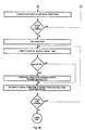
- the index i(gnor) for each subframe is calculated and for each value the comparison with Nn-1 is carried out, causing transmission of index i(s) corresponding to the null innovation word for the subframes where i(gnor)>Nn-1.
- index i(gmax) does not appear in the flow chart.
- the check is implicit in the initialization of i(gmax) to the value Nn before the search for the optimum excitation, since in this way this value will be issued as a value of i(gmax) if no indexes i(g) > Nn exist in the frame.
- Fig. 3 contains the diagram of a possible realization of block IT.
- This comprises a quantization circuit QU, quantizing, e.g. according to a logarithmic law, the gain values g determined by EL (Fig. 1) for each innovation word and present on a connection 1.
- QU supplies quantized values g and to M1 (connection 4) and also generates indexes i(g) which represent the quantized values.
- the index i(g) present at that instant at the output of QU is loaded in a buffer MT.
- the index i(g) present in MT (indicating the optimum gain for the specific subframe) is loaded, upon command of signal CK1 which has a period equal to that of a subframe, into the proper cell of a register R1, having as many cells as the subframes in a frame.
- This index is also loaded, upon command of the same signal CK1, into a comparison logic network CFR, which is able to recognize and to store into an internal register the maximum among the indexes received.
- the minimum value Nn admissible for i(gmax) will have been loaded before the beginning of the frame, so as to effect the above mentioned check.
- the value i(gmax) in the register of CFR (which as said before is one of the indexes i(g) or value Nn) is supplied by means of a connection 2a to the positive input of an adder S3 and transferred to index coding circuit CD. Reading of i(gmax) takes place upon command of a signal CK2, emitted after loading index i(g) relevant to the last subframe in a frame.
- Adder S3 receives in sequence from register R1 the values of indexes i(g) of the current frame by means of multiplexer MX controlled by a signal CK3, and subtracts each of them from i(gmax) giving the normalized values i[gnor(k)].
- a comparator CM compares indexes i(gnor) with a second threshold Nn-1 and at each comparison sends to circuit CD, via an output connection 2b, the value i(gnor), if it is less than or equal to Nn-1, otherwise it emits value Nn-1; CM also emits a signal indicating the result of the comparison, sent to EL by means of connection 3 to cause EL to send to CD the index corresponding to the null word when i(gnor) > Nn- 1.
- the aim of the invention is to allow a good efficiency of the gain coding, taking into account, with a high probability, the gain quantization effects in the optimum excitation search and in the computation of the synthesis filter initial conditions.
- the first aspect also implies that the total number Ng of quantization levels is rather limited.
- the gain codebook can be a logarithmic codebook, so that the ratio between two consecutive values is a constant. To design the codebook it is necessary to take into account several requirements:
- the described method actually eliminates the drawbacks of the known technique.
- quantized gain values are in any case calculated at each subframe and they can therefore be used in the search for the optimum word for individual subframes: in this way, except for the case of silencing, the optimization of the innovation word is improved since it takes into account quantization effects. The same effect is taken into consideration for initializing the filters at each subframe. In this way the distortion introduced will be reduced if compared to the case in which quantization effects are not taken into consideration.
- null innovation word could be decided beforehand (i.e. outside the analysis-by-synthesis loop) in order to represent with a perfect silence signal portions the energy of which is below a certain threshold or more generally signal portions for which such representation is deemed to be suitable from the perceptual standpoint (idle channel noise).
- This solution offers some advantages with respect to having the silencing carried out at the decoder since, in this way, the decoder is not bound to reconstruct the whole frame before effecting the silencing (to be assessed considering at least a complete frame) and it can immediately reproduce any subframe, as soon as it has the necessary information available, thus reducing the overall communication delay.
- the invention can be applied to the quantization of the excitation gain in any analysis-by-synthesis coder.
- gains can have a positive or a negative sign.
- the invention however concerns absolute value quantization: information about the sign, if necessary, will be supplied to CD by EL (Fig. 1) and transmitted through a special bit.
- the invention can be applied to coders where the innovation is supplied by different branches (with their respective gains), such as the coders described by I.A. Gerson and M.A. Iasuk in the paper "Vector Sum Excited Linear Prediction (VSELP) Speech Coding at 8 kbp/s” presented at International Conference on Acoustics, Speech and Signal Processing (ICASSP 90), Albuquerque (US), 3-6 April 1990, or by R. Drogo De Iacovo and D. Sereno in the paper "Embedded CELP coding for variable bit rate between 6,4 and 9,6 kbits/s” presented at International Conference on Acoustics, Speech and Signal Processing (ICASSP 91), Toronto (Canada), 14-17 May 1991.
- the gain quantization method remains as described.
- the normalized index is represented by the difference between gain index i(g) determined for the preceding branch in the same subframe and that of the branch being considered, and only the normalized index is transmitted.
- i(gnor) The dynamics of i(gnor) must be limited also for these branches, considering that i(gnor) can be positive or negative: more particularly, if i(gnor) is positive and exceeds a certain threshold, innovation will be silenced as before; if i(gnor) is too much negative, it is clipped to a preset value, e.g. -2, -1 or even 0, so that the innovation component supplied by that branch has a limited amplitude.
- the limits are obviously chosen so as to have low probabilities both of silencing and of clipping.
- the advantage as compared to the normalization with respect to i(gmax) also for the branches following the first one is twofold:
Landscapes
- Engineering & Computer Science (AREA)
- Computational Linguistics (AREA)
- Signal Processing (AREA)
- Health & Medical Sciences (AREA)
- Audiology, Speech & Language Pathology (AREA)
- Human Computer Interaction (AREA)
- Physics & Mathematics (AREA)
- Acoustics & Sound (AREA)
- Multimedia (AREA)
- Compression, Expansion, Code Conversion, And Decoders (AREA)
- Transmission Systems Not Characterized By The Medium Used For Transmission (AREA)
- Compression Or Coding Systems Of Tv Signals (AREA)
Claims (19)
- Verfahren zum Quantisieren der Erregungsamplitude in Sprachkodierern, die auf Analyse-durch-Synthese-Techniken basieren, bei dem Abtastwerte des zu kodierenden Sprachsignals in Rahmen organisiert werden, von denen jeder eine Mehrzahl von aneinanderstoßenden Teilrahmen umfaßt, für die jeweils ein Optimum-Erregungssignal durch Mindestwertbildung eines wahrnehmungsmäßig bedeutungsvollen Meßwerts der Verzerrung bestimmt werden muß, wobei dieses Erregungssignal einen ersten Beitrag, der eine Signalform wiedergibt, und einen zweiten Beitrag, der eine Signalamplitude wiedergibt, umfaßt und beide Beiträge in jeweiligen Gruppen gewählt werden, innerhalb derer jeder mögliche Beitrag durch einen Innovationsindex i[s(j)] bzw. einen Verstärkungsindex i[g(j)] identifiziert wird, dadurch gekennzeichnet, daß während des Kodierens der Amplitudenbeitrag des Erregungssignals für jeden Teilrahmen unter Bestimmung eines entsprechenden Verstärkungsindexes i(g) quantisiert wird; daß der Maximumwert i(gmax) des Verstärkungsindexes i(g) in einem Rahmen bestimmt wird; daß ein normalisierter Index i(gnor), der sich auf jeden Teilrahmen bezieht, als die Differenz zwischen dem Maximumindex i(gmax) und dem Teilrahmen-Verstärkungsindex i(g) berechnet wird; daß der Maximumindex i(gmax) und die Gruppe der normalisierten Indexe i(gnor) kodiert und gesendet werden, um die sich auf einen Rahmen beziehenden Amplitudenbeiträge wiederzugeben; und daß beim Dekodieren der Verstärkungsindex i(g) jedes Teilrahmens rekonstruiert wird, und zwar ausgehend vom Maximumindex i(gmax) im Rahmen und vom normalisierten Index i(gnor), der sich auf den Teilrahmen bezieht.
- Verfahren nach Anspruch 1, dadurch gekennzeichnet, daß der Maximumindex und alle normalisierten Indexe quantisierte Amplitudenwerte innerhalb einer selben Gruppe identifizieren.
- Verfahren nach Anspruch 2, dadurch gekennzeichnet, daß im Fall, in dem der Maximumindex in einem Rahmen i(gmax) einen quantisierten Amplitudenwert identifiziert, der niedriger liegt als eine erste Schwelle, der dieser ersten Schwelle zugeordnete Verstärkungsindex dazu verwendet wird, die normalisierten Indexe i(gnor) zu bestimmen, und anstelle des Maximumindexes kodiert und gesendet wird.
- Verfahren nach Anspruch 2 oder 3, dadurch gekennzeichnet, daß die Gruppe der Form-Beiträge auch einen Null-Beitrag umfaßt und daß dann, wenn der normalisierte Index i(gnor) in einem Teilrahmen einen quantisierten Amplitudenwert identifiziert, der höher ist als eine zweite Schwelle, die betreffende Information mit Hilfe des Innovationsindexes gesendet wird, der dem Null-Form-Beitrag entspricht, um so die Erregung für diesen Teilrahmen auf "Schweigen" zu setzen.
- Verfahren nach Anspruch 4, dadurch gekennzeichnet, daß der dieser zweiten Schwelle zugeordnete Index als normalisierter Index kodiert und gesendet wird.
- Verfahren nach einem der vorhergehenden Ansprüche, dadurch gekennzeichnet, daß das Erregungssignal für einen Teilrahmen als eine Kombination von Erregungen erhalten wird, die in getrennten Untergruppen gewählt werden, umfassend eine Haupt-Untergruppe und eine oder mehrere sekundäre Untergruppen; daß für die Haupt-Untergruppe derAmplitudenbeitrag durch Verwendung des Maximum-Indexes und der normalisierten Indexe quantisiert wird; und daß für die oder für jede sekundäre Untergruppe der Amplituden-Beitrag nur mit Hilfe einer Gruppe differentieller Indexe quantisiert wird, nämlich eines je Teilrahmen, wobei jeder differentielle Index, der sich auf die oder eine der sekundären Untergruppen bezieht, durch Subtrahieren des sich auf die vorliegende sekundäre Untergruppe beziehenden Verstärkungsindexes vom für den selben Teilrahmen für die vorhergehende sekundäre Untergruppe oder für die Haupt-Untergruppe, im Fall der ersten sekundären Untergruppe oder einer einzigen sekundären Untergruppe, bestimmten Verstärkungsindex erhalten wird.
- Verfahren nach Anspruch 6, dadurch gekennzeichnet, daß im Fall, daß ein differentieller Index höher ist als ein erster voreingestellter positiver Wert, der entsprechende Erregungs-Form-Beitrag auf "Schweigen" gesetzt wird, und im Fall, daß ein differentieller Index niedriger ist als ein zweiter voreingestellter Wert, ihm ein Wert gegeben wird, der nicht niedriger ist als der zweite voreingestellte Wert.
- Verfahren nach einem der vorhergehenden Ansprüche, dadurch gekennzeichnet, daß der Amplitudenbeitrag nach einem logarithmischen Quantisierungsgesetz quantisiert wird.
- Verfahren nach einem der vorhergehenden Ansprüche, dadurch gekennzeichnet, daß die Erregung jedesmal dann auf "Schweigen" gesetzt wird, und zwar für wenigstens einen Rahmen, indem man für alle Teilrahmen den dem Null-Form-Beitrag entsprechenden Innovationsindex sendet, wenn die Charakteristiken des zu kodierenden Signals so sind, daß sie von einem Wahrnehmungsstandpunktaus eine Signalreproduktion durch eine Schweigeperiode zweckmäßig machen.
- Verfahren nach dem auf die Ansprüche 4 und 5 rückbezogenen Anspruch 9, dadurch gekennzeichnet, daß die der ersten und der zweiten Schwelle entsprechenden Werte als Indexe i(gmax) und i(gnor) gesendet werden.
- Vorrichtung zum Quantisieren der Erregungsamplitude in Sprachkodierem, die auf Analyse-durch-Synthese-Techniken beruhen, bei der zu kodierende Abtastwerte des Sprachsignals in Rahmen unterteilt werden, von denen jeder eine Mehrzahl aneinanderstoßender Teilrahmen umfaßt, und für jeden der Teilrahmen ein Optimum-Erregungssignal durch Mindestwertbildung eines wahrnehmungsmäßig bedeutungsvollen Meßwerts der Verzerrung bestimmt wird, wobei das Erregungssignal einen ersten Beitrag, der die Signalform wiedergibt, und einen zweiten Beitrag, der die Signalamplitude wiedergibt, umfaßt und beide Beiträge in jeweiligen Gruppen gewählt werden, innerhalb derer jeder mögliche Beitrag durch einen Innovationsindex i[s(j)] bzw. einem Verstärkungsindex i[g(j)] identifiziert wird, dadurch gekennzeichnet, daß die Vorrichtung senderseitig folgende Einrichtungen umfaßt:und daß die Vorrichtung empfängerseitig eine Einrichtung (S2) zum Rekonstruieren eines Verstärkungsindexes i(g) für jeden Teilrahmen, ausgehend vom Maximum-Index und von den normalisierten Indexen, die in einer Dekodierschaltung (DC) dekodiert wurden, und zum Liefern dieses Verstärkungsindexes i(g) als Leseadresse an einen Speicher (VG), der die Gruppe quantisierter Amplitudenwerte enthält, umfaßt.eine Einrichtung (QU) zum Quantisieren von Amplitudenbeitrag-Werten, die durch eine Verzerrungsminimalisierungseinheit (EL) für jeden möglichen Form-Beitrag bestimmt werden, wobei die Quantisierungseinrichtung (QU) quantisierteAmplitudenwerte und diese wiedergebende Verstärkungsindexe liefert;eine Vergleichs-Logikschaltung (CFR), die von der Quantisierungseinrichtung bei jedem Teilrahmen denjenigen Verstärkungsindex i(g) empfängt, der den Optimum-Amplitudenbeitrag für diesen Teilrahmen identifiziert, und der dazu aufgebaut ist, den Maximum-Index i(gmax) unter den empfangenen Verstärkungsindexen am Ende eines Rahmens zu erkennen und ihn an eine Index-Kodierschaltung (CD) zu liefern;eine Einrichtung (R1) zum vorübergehenden Speichern der auf einen Rahmen bezogenen Verstärkungsindexe i(g); undeine Einrichtung (S3) zum Berechnen einer Gruppe normalisierter Indexe i(gnor), nämlich einer je Teilrahmen, die von der Vergleichs-Logikschaltung (CFR) den Maximum-Index und von der Speichereinrichtung (R1) die gespeicherten Verstärkungsindexe empfängt und die Gruppe normalisierter Indexe als die Differenz zwischen dem Maximum-Index i(gmax) und jedem der in der Speichereinrichtung gespeicherten Indexe i(g) berechnet, wobei die normalisierten Indexe an die Index-Kodierschaltung (CD) geliefert werden;
- Vorrichtung nach Anspruch 11, dadurch gekennzeichnet, daß die Quantisierungsschaltung (QU) die Amplituden-beitrag-Werte nach einem logarithmischen Maßstab quantisiert.
- Vorrichtung nach Anspruch 11 oder 12, dadurch gekennzeichnet, daß die Vergleichs-Logikschaltung (CFR) zu Beginn jedes Rahmens für den Maximum-Index i(gmax) einen Anfangswert speichert, der einen ersten Schwellenwert darstellt, welcher den zulässigen Mindestwert für den Maximum-Index i(gmax) wiedergibt.
- Vorrichtung nach Anspruch 11, dadurch gekennzeichnet, daß die Einrichtung (S3) zum Berechnen der normalisierten Indexe diese an eine Vergleichseinrichtung (CM) liefert, die jeden normalisierten Index mit einem zweiten Schwellenwert vergleicht und ausgangsseitig bei jedem Vergleich entweder den normalisierten Index oder den zweiten Schwellenwert abgibt, je nachdem, welcher von beiden der höhere ist.
- Vorrichtung nach Anspruch 14, dadurch gekennzeichnet, daß die Vergleichseinrichtung (CM) jedesmal dann, wenn ein normalisierter Index den zweiten Schwellenwert übersteigt, dieses Übersteigen auch an die Minimalisierungseinheit (EL) meldet, um den entsprechenden Form-Beitrag des Erregungssignals durch Senden des einem Null-Form-Beitrag entsprechenden Innovationsindexes auf "Schweigen" zu setzen.
- Verfahren der Sprachsignalkodierung durch Analyse-durch-Synthese-Techniken, bei dem Abtastwerte des zu kodierenden Sprachsignals in Rahmen organisiert werden, von denen jeder eine Mehrzahl von aneinanderstoßenden Teilrahmen umfaßt, für die jeweils ein Optimum-Erregungssignal durch Mindestwertbildung eines wahrnehmungsmäßig bedeutungsvollen Meßwerts der Verzerrung bestimmt werden muß, wobei das Erregungssignal einen ersten Beitrag, der eine Signalform wiedergibt, und einen zweiten Beitrag, der eine Signalamplitude wiedergibt, umfaßt, welche in jeweiligen Gruppen gewählt werden, innerhalb derer jeder mögliche Beitrag durch einen Innovationsindex i[s(j)] bzw. einen Verstärkungsindex i[g(j)] identifiziert wird, dadurch gekennzeichnet, daß der Amplitudenbeitrag nach dem Verfahren gemäß einem der Ansprüche 1 bis 10 quantisiert wird.
- Verfahren nach Anspruch 16, dadurch gekennzeichnet, daß für die Verzerrungs-Mindestwertbildung in jedem Teilrahmen quantisierte Werte des Amplitudenbeitrags verwendet werden und daß bei jedem neuen Teilrahmen die Anfangsbedingungen eines Synthesefilters, der den Spracherzeugungsapparat simuliert, berechnet werden durch Verwendung des quantisierten Werts des Amplitudenbeitrags des Erregungssignals des vorhergehenden Teilrahmens.
- Verfahren nach Anspruch 17, dadurch gekennzeichnet, daß die Anfangsbedingungen des Synthesefilters erneut nach der Bestimmung der normalisierten Indexe berechnet werden.
- Sprachkodierer, der Analyse-durch-Synthese-Techniken anwendet, mit senderseits einem Filterungssystems (FS1), das den Spracherzeugungsapparat simuliert und mit einem Erregungssignals gespeist wird, das innerhalb einer Gruppe von Signalen so gewählt wird, daß ein wahrnehmungsmäßig bedeutungsvoller Meßwert der Verzerrung minimalisiert wird, und das aus einem Form-Beitrag und einem Amplitudenbeitrag gebildet wird, und mit einer Einrichtung (EL, IT) zum Quantisieren dieser Beiträge, dadurch gekennzeichnet, daß die Einrichtung (IT) zum Quantisieren des Amplitudenbeitrags eine Vorrichtung nach einem der Ansprüche 11 bis 15 umfaßt.
Applications Claiming Priority (2)
| Application Number | Priority Date | Filing Date | Title |
|---|---|---|---|
| ITTO920982A IT1257431B (it) | 1992-12-04 | 1992-12-04 | Procedimento e dispositivo per la quantizzazione dei guadagni dell'eccitazione in codificatori della voce basati su tecniche di analisi per sintesi |
| ITTO920982 | 1992-12-04 |
Publications (2)
| Publication Number | Publication Date |
|---|---|
| EP0600504A1 EP0600504A1 (de) | 1994-06-08 |
| EP0600504B1 true EP0600504B1 (de) | 1998-10-07 |
Family
ID=11410902
Family Applications (1)
| Application Number | Title | Priority Date | Filing Date |
|---|---|---|---|
| EP93119522A Expired - Lifetime EP0600504B1 (de) | 1992-12-04 | 1993-12-03 | Verfahren und Vorrichtung für Sprachkodierung auf der Basis von Analyse-durch-Synthesetechniken |
Country Status (10)
| Country | Link |
|---|---|
| US (1) | US5519807A (de) |
| EP (1) | EP0600504B1 (de) |
| JP (1) | JP3204581B2 (de) |
| AT (1) | ATE172045T1 (de) |
| CA (1) | CA2110645C (de) |
| DE (2) | DE600504T1 (de) |
| ES (1) | ES2054606T3 (de) |
| FI (1) | FI115327B (de) |
| GR (1) | GR940300069T1 (de) |
| IT (1) | IT1257431B (de) |
Families Citing this family (13)
| Publication number | Priority date | Publication date | Assignee | Title |
|---|---|---|---|---|
| TW419645B (en) * | 1996-05-24 | 2001-01-21 | Koninkl Philips Electronics Nv | A method for coding Human speech and an apparatus for reproducing human speech so coded |
| US6584181B1 (en) | 1997-09-19 | 2003-06-24 | Siemens Information & Communication Networks, Inc. | System and method for organizing multi-media messages folders from a displayless interface and selectively retrieving information using voice labels |
| US6370238B1 (en) | 1997-09-19 | 2002-04-09 | Siemens Information And Communication Networks Inc. | System and method for improved user interface in prompting systems |
| US6069940A (en) * | 1997-09-19 | 2000-05-30 | Siemens Information And Communication Networks, Inc. | Apparatus and method for adding a subject line to voice mail messages |
| SE519563C2 (sv) * | 1998-09-16 | 2003-03-11 | Ericsson Telefon Ab L M | Förfarande och kodare för linjär prediktiv analys-genom- synteskodning |
| CA2252170A1 (en) * | 1998-10-27 | 2000-04-27 | Bruno Bessette | A method and device for high quality coding of wideband speech and audio signals |
| DE60214027T2 (de) * | 2001-11-14 | 2007-02-15 | Matsushita Electric Industrial Co., Ltd., Kadoma | Kodiervorrichtung und dekodiervorrichtung |
| DE10249386B3 (de) * | 2002-10-23 | 2004-07-08 | Pingo Erzeugnisse Gmbh | Mittel zur präventiven und abwehrenden Bekämpfung von Metallbränden |
| US7542899B2 (en) * | 2003-09-30 | 2009-06-02 | Alcatel-Lucent Usa Inc. | Method and apparatus for adjusting the level of a speech signal in its encoded format |
| US8265929B2 (en) * | 2004-12-08 | 2012-09-11 | Electronics And Telecommunications Research Institute | Embedded code-excited linear prediction speech coding and decoding apparatus and method |
| US9454974B2 (en) * | 2006-07-31 | 2016-09-27 | Qualcomm Incorporated | Systems, methods, and apparatus for gain factor limiting |
| CA2778240C (en) * | 2009-10-20 | 2016-09-06 | Fraunhofer Gesellschaft Zur Foerderung Der Angewandten Forschung E.V. | Multi-mode audio codec and celp coding adapted therefore |
| US10373608B2 (en) * | 2015-10-22 | 2019-08-06 | Texas Instruments Incorporated | Time-based frequency tuning of analog-to-information feature extraction |
Family Cites Families (12)
| Publication number | Priority date | Publication date | Assignee | Title |
|---|---|---|---|---|
| CA1229681A (en) * | 1984-03-06 | 1987-11-24 | Kazunori Ozawa | Method and apparatus for speech-band signal coding |
| US4704730A (en) * | 1984-03-12 | 1987-11-03 | Allophonix, Inc. | Multi-state speech encoder and decoder |
| CA1255802A (en) * | 1984-07-05 | 1989-06-13 | Kazunori Ozawa | Low bit-rate pattern encoding and decoding with a reduced number of excitation pulses |
| JPS6332599A (ja) * | 1986-07-25 | 1988-02-12 | 松下電器産業株式会社 | 音声符号化装置 |
| US4771465A (en) * | 1986-09-11 | 1988-09-13 | American Telephone And Telegraph Company, At&T Bell Laboratories | Digital speech sinusoidal vocoder with transmission of only subset of harmonics |
| US4803730A (en) * | 1986-10-31 | 1989-02-07 | American Telephone And Telegraph Company, At&T Bell Laboratories | Fast significant sample detection for a pitch detector |
| US5018200A (en) * | 1988-09-21 | 1991-05-21 | Nec Corporation | Communication system capable of improving a speech quality by classifying speech signals |
| WO1990013112A1 (fr) * | 1989-04-25 | 1990-11-01 | Kabushiki Kaisha Toshiba | Codeur vocal |
| IT1232084B (it) * | 1989-05-03 | 1992-01-23 | Cselt Centro Studi Lab Telecom | Sistema di codifica per segnali audio a banda allargata |
| US5144671A (en) * | 1990-03-15 | 1992-09-01 | Gte Laboratories Incorporated | Method for reducing the search complexity in analysis-by-synthesis coding |
| DE69129329T2 (de) * | 1990-09-14 | 1998-09-24 | Fujitsu Ltd | Sprachkodierungsystem |
| US5369724A (en) * | 1992-01-17 | 1994-11-29 | Massachusetts Institute Of Technology | Method and apparatus for encoding, decoding and compression of audio-type data using reference coefficients located within a band of coefficients |
-
1992
- 1992-12-04 IT ITTO920982A patent/IT1257431B/it active IP Right Grant
-
1993
- 1993-10-12 US US08/135,298 patent/US5519807A/en not_active Expired - Lifetime
- 1993-12-02 JP JP32962093A patent/JP3204581B2/ja not_active Expired - Lifetime
- 1993-12-03 DE DE0600504T patent/DE600504T1/de active Pending
- 1993-12-03 EP EP93119522A patent/EP0600504B1/de not_active Expired - Lifetime
- 1993-12-03 FI FI935423A patent/FI115327B/fi not_active IP Right Cessation
- 1993-12-03 DE DE69321444T patent/DE69321444T2/de not_active Expired - Lifetime
- 1993-12-03 AT AT93119522T patent/ATE172045T1/de active
- 1993-12-03 ES ES93119522T patent/ES2054606T3/es not_active Expired - Lifetime
- 1993-12-03 CA CA002110645A patent/CA2110645C/en not_active Expired - Lifetime
-
1994
- 1994-10-31 GR GR940300069T patent/GR940300069T1/el unknown
Also Published As
| Publication number | Publication date |
|---|---|
| IT1257431B (it) | 1996-01-16 |
| DE600504T1 (de) | 1994-12-08 |
| FI115327B (fi) | 2005-04-15 |
| FI935423A0 (fi) | 1993-12-03 |
| ES2054606T3 (es) | 1998-12-16 |
| GR940300069T1 (en) | 1994-10-31 |
| ITTO920982A0 (it) | 1992-12-04 |
| ES2054606T1 (es) | 1994-08-16 |
| JPH06348300A (ja) | 1994-12-22 |
| JP3204581B2 (ja) | 2001-09-04 |
| CA2110645A1 (en) | 1994-06-05 |
| CA2110645C (en) | 1998-06-16 |
| US5519807A (en) | 1996-05-21 |
| FI935423A7 (fi) | 1994-06-05 |
| ITTO920982A1 (it) | 1994-06-04 |
| EP0600504A1 (de) | 1994-06-08 |
| DE69321444D1 (de) | 1998-11-12 |
| DE69321444T2 (de) | 1999-04-22 |
| ATE172045T1 (de) | 1998-10-15 |
Similar Documents
| Publication | Publication Date | Title |
|---|---|---|
| EP0504627B1 (de) | Verfahren und Vorrichtung zur Kodierung von Sprachparametern | |
| US6073092A (en) | Method for speech coding based on a code excited linear prediction (CELP) model | |
| US6014622A (en) | Low bit rate speech coder using adaptive open-loop subframe pitch lag estimation and vector quantization | |
| US5675702A (en) | Multi-segment vector quantizer for a speech coder suitable for use in a radiotelephone | |
| CN1820306B (zh) | 可变比特率宽带语音编码中增益量化的方法和装置 | |
| EP0600504B1 (de) | Verfahren und Vorrichtung für Sprachkodierung auf der Basis von Analyse-durch-Synthesetechniken | |
| EP1093116A1 (de) | Autokorrelation basierte Suchschleife für CELP Sprachkodierer | |
| US7065338B2 (en) | Method, device and program for coding and decoding acoustic parameter, and method, device and program for coding and decoding sound | |
| US6249758B1 (en) | Apparatus and method for coding speech signals by making use of voice/unvoiced characteristics of the speech signals | |
| US4963034A (en) | Low-delay vector backward predictive coding of speech | |
| US6148282A (en) | Multimodal code-excited linear prediction (CELP) coder and method using peakiness measure | |
| EP1114414B1 (de) | Adaptives kriterium für die sprachkodierung | |
| US6205423B1 (en) | Method for coding speech containing noise-like speech periods and/or having background noise | |
| EP0778561B1 (de) | Vorrichtung zur Sprachkodierung | |
| US5526464A (en) | Reducing search complexity for code-excited linear prediction (CELP) coding | |
| EP0578436B1 (de) | Selektive Anwendung von Sprachkodierungstechniken | |
| EP0747884A2 (de) | Abschwächung der Kodebuchverstärkung bei Ausfall von Datenrahmen | |
| US5797119A (en) | Comb filter speech coding with preselected excitation code vectors | |
| US4945567A (en) | Method and apparatus for speech-band signal coding | |
| JPH02231825A (ja) | 音声符号化方法、音声復号方法、およびこれらを使用した通信方法 | |
| Tseng | An analysis-by-synthesis linear predictive model for narrowband speech coding | |
| EP0910064B1 (de) | Sprachparameterkodierungsvorrichtung | |
| Zinser et al. | 4800 and 7200 bit/sec hybrid codebook multipulse coding | |
| JPH05273999A (ja) | 音声符号化方法 | |
| Chui et al. | A hybrid input/output spectrum adaptation scheme for LD-CELP coding of speech |
Legal Events
| Date | Code | Title | Description |
|---|---|---|---|
| PUAI | Public reference made under article 153(3) epc to a published international application that has entered the european phase |
Free format text: ORIGINAL CODE: 0009012 |
|
| AK | Designated contracting states |
Kind code of ref document: A1 Designated state(s): AT BE CH DE ES FR GB GR IT LI NL SE |
|
| 17P | Request for examination filed |
Effective date: 19940511 |
|
| TCAT | At: translation of patent claims filed | ||
| EL | Fr: translation of claims filed | ||
| REG | Reference to a national code |
Ref country code: ES Ref legal event code: BA2A Ref document number: 2054606 Country of ref document: ES Kind code of ref document: T1 |
|
| TCNL | Nl: translation of patent claims filed | ||
| DET | De: translation of patent claims | ||
| RTI1 | Title (correction) | ||
| GRAG | Despatch of communication of intention to grant |
Free format text: ORIGINAL CODE: EPIDOS AGRA |
|
| 17Q | First examination report despatched |
Effective date: 19970509 |
|
| GRAG | Despatch of communication of intention to grant |
Free format text: ORIGINAL CODE: EPIDOS AGRA |
|
| RAP1 | Party data changed (applicant data changed or rights of an application transferred) |
Owner name: TELECOM ITALIA MOBILE S.P.A. |
|
| GRAG | Despatch of communication of intention to grant |
Free format text: ORIGINAL CODE: EPIDOS AGRA |
|
| GRAH | Despatch of communication of intention to grant a patent |
Free format text: ORIGINAL CODE: EPIDOS IGRA |
|
| GRAH | Despatch of communication of intention to grant a patent |
Free format text: ORIGINAL CODE: EPIDOS IGRA |
|
| GRAA | (expected) grant |
Free format text: ORIGINAL CODE: 0009210 |
|
| AK | Designated contracting states |
Kind code of ref document: B1 Designated state(s): AT BE CH DE ES FR GB GR IT LI NL SE |
|
| REF | Corresponds to: |
Ref document number: 172045 Country of ref document: AT Date of ref document: 19981015 Kind code of ref document: T |
|
| REG | Reference to a national code |
Ref country code: CH Ref legal event code: NV Representative=s name: BOVARD AG PATENTANWAELTE Ref country code: CH Ref legal event code: EP |
|
| REF | Corresponds to: |
Ref document number: 69321444 Country of ref document: DE Date of ref document: 19981112 |
|
| REG | Reference to a national code |
Ref country code: ES Ref legal event code: FG2A Ref document number: 2054606 Country of ref document: ES Kind code of ref document: T3 |
|
| ET | Fr: translation filed | ||
| PLBE | No opposition filed within time limit |
Free format text: ORIGINAL CODE: 0009261 |
|
| STAA | Information on the status of an ep patent application or granted ep patent |
Free format text: STATUS: NO OPPOSITION FILED WITHIN TIME LIMIT |
|
| 26N | No opposition filed | ||
| REG | Reference to a national code |
Ref country code: GB Ref legal event code: IF02 |
|
| REG | Reference to a national code |
Ref country code: CH Ref legal event code: PFA Owner name: TELECOM ITALIA MOBILE S.P.A. Free format text: TELECOM ITALIA MOBILE S.P.A.#VIA BERTOLA, 34#10122 TORINO (IT) -TRANSFER TO- TELECOM ITALIA MOBILE S.P.A.#VIA BERTOLA, 34#10122 TORINO (IT) |
|
| PGFP | Annual fee paid to national office [announced via postgrant information from national office to epo] |
Ref country code: CH Payment date: 20121226 Year of fee payment: 20 |
|
| PGFP | Annual fee paid to national office [announced via postgrant information from national office to epo] |
Ref country code: GR Payment date: 20121228 Year of fee payment: 20 Ref country code: GB Payment date: 20121227 Year of fee payment: 20 Ref country code: IT Payment date: 20121220 Year of fee payment: 20 |
|
| PGFP | Annual fee paid to national office [announced via postgrant information from national office to epo] |
Ref country code: FR Payment date: 20130110 Year of fee payment: 20 Ref country code: AT Payment date: 20121121 Year of fee payment: 20 |
|
| PGFP | Annual fee paid to national office [announced via postgrant information from national office to epo] |
Ref country code: SE Payment date: 20130102 Year of fee payment: 20 Ref country code: DE Payment date: 20121231 Year of fee payment: 20 Ref country code: BE Payment date: 20121227 Year of fee payment: 20 Ref country code: ES Payment date: 20121226 Year of fee payment: 20 |
|
| PGFP | Annual fee paid to national office [announced via postgrant information from national office to epo] |
Ref country code: NL Payment date: 20121225 Year of fee payment: 20 |
|
| REG | Reference to a national code |
Ref country code: DE Ref legal event code: R071 Ref document number: 69321444 Country of ref document: DE |
|
| REG | Reference to a national code |
Ref country code: DE Ref legal event code: R071 Ref document number: 69321444 Country of ref document: DE |
|
| REG | Reference to a national code |
Ref country code: NL Ref legal event code: V4 Effective date: 20131203 |
|
| REG | Reference to a national code |
Ref country code: CH Ref legal event code: PL |
|
| REG | Reference to a national code |
Ref country code: GB Ref legal event code: PE20 Expiry date: 20131202 |
|
| BE20 | Be: patent expired |
Owner name: *TELECOM ITALIA MOBILE S.P.A. Effective date: 20131203 |
|
| REG | Reference to a national code |
Ref country code: AT Ref legal event code: MK07 Ref document number: 172045 Country of ref document: AT Kind code of ref document: T Effective date: 20131203 |
|
| PG25 | Lapsed in a contracting state [announced via postgrant information from national office to epo] |
Ref country code: GB Free format text: LAPSE BECAUSE OF EXPIRATION OF PROTECTION Effective date: 20131202 Ref country code: DE Free format text: LAPSE BECAUSE OF EXPIRATION OF PROTECTION Effective date: 20131204 |
|
| REG | Reference to a national code |
Ref country code: SE Ref legal event code: EUG |
|
| REG | Reference to a national code |
Ref country code: GR Ref legal event code: MA Ref document number: 980401494 Country of ref document: GR Effective date: 20131204 |
|
| REG | Reference to a national code |
Ref country code: ES Ref legal event code: FD2A Effective date: 20140210 |
|
| PG25 | Lapsed in a contracting state [announced via postgrant information from national office to epo] |
Ref country code: ES Free format text: LAPSE BECAUSE OF EXPIRATION OF PROTECTION Effective date: 20131204 |
|
| PG25 | Lapsed in a contracting state [announced via postgrant information from national office to epo] |
Ref country code: BE Free format text: THE PATENT HAS BEEN ANNULLED BY A DECISION OF A NATIONAL AUTHORITY Effective date: 19981007 |