EP0600274B1 - Roller skate with braking device - Google Patents
Roller skate with braking device Download PDFInfo
- Publication number
- EP0600274B1 EP0600274B1 EP93118202A EP93118202A EP0600274B1 EP 0600274 B1 EP0600274 B1 EP 0600274B1 EP 93118202 A EP93118202 A EP 93118202A EP 93118202 A EP93118202 A EP 93118202A EP 0600274 B1 EP0600274 B1 EP 0600274B1
- Authority
- EP
- European Patent Office
- Prior art keywords
- quarter
- braking
- cable
- pivot
- skate according
- Prior art date
- Legal status (The legal status is an assumption and is not a legal conclusion. Google has not performed a legal analysis and makes no representation as to the accuracy of the status listed.)
- Expired - Lifetime
Links
- 230000003993 interaction Effects 0.000 claims description 14
- 238000005096 rolling process Methods 0.000 claims description 14
- 230000004913 activation Effects 0.000 claims description 6
- 230000007935 neutral effect Effects 0.000 claims description 4
- 230000009471 action Effects 0.000 abstract description 9
- 230000008901 benefit Effects 0.000 description 5
- 208000018883 loss of balance Diseases 0.000 description 3
- 206010003591 Ataxia Diseases 0.000 description 1
- 206010010947 Coordination abnormal Diseases 0.000 description 1
- 208000012661 Dyskinesia Diseases 0.000 description 1
- 208000015592 Involuntary movements Diseases 0.000 description 1
- 230000009849 deactivation Effects 0.000 description 1
- 208000028756 lack of coordination Diseases 0.000 description 1
- 230000000670 limiting effect Effects 0.000 description 1
- 238000004519 manufacturing process Methods 0.000 description 1
- 230000004048 modification Effects 0.000 description 1
- 238000012986 modification Methods 0.000 description 1
- 230000017311 musculoskeletal movement, spinal reflex action Effects 0.000 description 1
- 230000009467 reduction Effects 0.000 description 1
- 230000000284 resting effect Effects 0.000 description 1
Images


Classifications
-
- A—HUMAN NECESSITIES
- A63—SPORTS; GAMES; AMUSEMENTS
- A63C—SKATES; SKIS; ROLLER SKATES; DESIGN OR LAYOUT OF COURTS, RINKS OR THE LIKE
- A63C17/00—Roller skates; Skate-boards
- A63C17/14—Roller skates; Skate-boards with brakes, e.g. toe stoppers, freewheel roller clutches
- A63C17/1409—Roller skates; Skate-boards with brakes, e.g. toe stoppers, freewheel roller clutches contacting one or more of the wheels
-
- A—HUMAN NECESSITIES
- A63—SPORTS; GAMES; AMUSEMENTS
- A63C—SKATES; SKIS; ROLLER SKATES; DESIGN OR LAYOUT OF COURTS, RINKS OR THE LIKE
- A63C17/00—Roller skates; Skate-boards
- A63C17/14—Roller skates; Skate-boards with brakes, e.g. toe stoppers, freewheel roller clutches
- A63C17/1436—Roller skates; Skate-boards with brakes, e.g. toe stoppers, freewheel roller clutches contacting the ground
Definitions
- the present invention relates to an in-line roller skate comprising a braking device, the skate including a shoe composed of a quarter articulated to a shell which is in turn associated with a frame for supporting one or more wheels.
- roller skates whether constituted by a shoe associated with a support for two pairs of mutually parallel wheels or by a shoe associated with a supporting frame for one or more aligned wheels, there is currently the problem of braking the wheels in order to adjust the speed of the skate.
- US Patent No. 1,402,010 discloses a roller skate provided with a band which can be secured on the user's leg above the malleolar region and to which a rod is connected.
- Said rod surrounds the leg to the rear and is then curved so as to laterally affect the leg until it is associated, at its ends, in the malleolar region, with a lever system which is articulated to a structure protruding from the wheel supporting frame.
- the lever system protrudes to the rear of the frame and is connected to a plate which is shaped approximately complementarily to the curvature of part of an underlying facing wheel.
- the plate is activated every time the user bends his leg backwards beyond a given angle, with no actual and easy possibility of varying this condition.
- the rod rests and presses on the malleolar region, and this can cause discomfort or can cause accidental impacts.
- the brake is constituted by a flap which is associated with the shoe in a rearward region and with which a plate is associated in a rearward position.
- the plate is pivoted at the supporting frame of the shoe.
- the plate has, at its free end, a transverse element on which a pair of C-shaped elements is formed at the lateral ends; following a backward rotation imparted to the flap, the C-shaped elements interact with the rear wheels facing them, in that they interact with the rolling surface of the wheels.
- the structural configuration of the brake causes the pair of C-shaped elements to interact with the wheel even upon a minimal backward rotation imparted to the flap and therefore even for involuntary movements, and this creates unwanted braking actions and thus possible loss of balance or lack of coordination.
- US Patent No. 4,300,781 discloses a braking device for skates which comprise pairs of mutually parallel wheels.
- the brake is constituted by a plate which is pivoted transversely at the rear end of the frame for supporting a shoe. Blocks are associated with the ends of the plate and face the rolling surface of the pair of rear wheels.
- the brake is activated by using a cable which is suitable to rotate the plate in contrast with a spring associated with the support for the pair of front wheels, so as to move the blocks into contact with the rolling surface of the pair of rear wheels.
- the cable can be activated by means of rings or handles associated with a band which can be arranged on the legs of the user by virtue of the presence of temporary connection means.
- the loose cable is a hindrance to the skater and could accidentally catch during skating, especially since coordination of the arm-legs movement rhythmically moves the legs laterally outwards.
- the aim of the present invention is therefore to eliminate the drawbacks described above in conventional skates by providing an in-line skate comprising a braking device which is structurally very simple and easy to industrialize.
- an object is to provide a braking device which can be activated by the user in case of actual need and not accidentally.
- Another important object is to provide a braking device which can be activated rapidly, easily and safely by the user without forcing the user to perform movements, for example with his hands, which would compromise his/her balance or coordination.
- Another important object is to provide a braking device which considerably reduces the wear of the rolling surface of the wheels.
- Another important object is to obtain a device which associates with the preceding characteristics that of being reliable and safe in use, has low manufacturing costs and can also be applied to conventional skates.
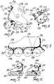
- the reference numeral 1 designates the braking device, which is particularly usable for a skate, designated by the reference numeral 2.
- the skate comprises a shoe 3 which is composed of a quarter 4 which surrounds the rear lateral region of the user's leg and is articulated to a shell 5 with which a frame 6 is associated in a lower region.
- the frame 6 has a cross-section shaped like an inverted U and supports one or more wheels which are designated by the reference numeral 7 and may be mutually aligned.
- Conventional levers 8 may be applied for securing the quarter 4 and the shell 5.
- the braking device comprises at least one traction element, generally designated by the reference numeral 9, which is preferably constituted by a cable, a first portion 10 whereof surrounds externally around the quarter 4 to the rear and is associated therewith at an adapted engagement means 11 such as a rack or a toothed region arranged longitudinally and to the rear of said quarter 4.
- the cable is guided inside the shoe 3 by virtue of the presence of an adapted pair of holes 12 formed laterally with respect to the quarter 4.
- a first pair of stop elements 13 for a pair of cable guiding sheaths 14 is associated inside the quarter.
- the sheaths protrude below the sole 15 of the shell 5 and are locked, by means of a second pair of stop elements 16, inside the wings 18 of the frame 6.
- the braking element 17 is composed of a brake which is constituted by a block 20 which is articulated transversely, by means of a pivot 21, to the frame 6 above the region where the sheath 14 is locked.
- the cable has a second portion 22 which protrudes from the sheaths and passes within an adapted seat 23 which is formed transversely with respect to the block 20.
- a pair of springs 24 is also interposed coaxially to the cable between the seat 23 and the second pair of stop elements 16.
- the springs allow the elastic return of the block to the original positions once the backward rotation of said quarter has ended.
- the use of the braking device is in fact as follows: by virtue of the connection of the block 17 to the quarter 4 by means of the traction element 9, a backward rotation imparted by the user to the quarter 4 is followed by a traction imparted to the cable, which makes the block rotate counterclockwise with respect to the pivot 21, so as to interact with the ground.
- the selection for the position of the first portion 10 of the traction element at the engagement means 11 thus allows both to compensate any wear of the block and to vary the extent of the inclination of the quarter before the block interacts with the ground.
- the spring allows the block to return to its initial position and thus rise from the ground.
- a braking device having been obtained which can be activated by the user at a presettable angle of backward rotation of the quarter, and this can be achieved by giving the desired length to the traction element and/or by varying the position thereof with respect to the quarter 4.
- both activation and deactivation of the braking element can be achieved in a very simple manner, allowing the user to assume a position suitable to control the braking action and thus maintaining the optimum balance condition and coordination in arm-legs movements.
- the invention is furthermore structurally simple and easy to industrialize, and can also be easily applied to conventional skates.
- the braking device according to the invention is naturally susceptible to numerous modifications and variations, all of which are within the scope of the claims.
- figure 2 illustrates a second embodiment of the braking device 101 wherein the traction element 109 is again constituted by a cable which is guided within a pair of sheaths 114 which protrude below the sole 115 of the shell 105 and are locked at a second pair of stop elements 116 which are associated at the lateral wings of the frame 106.
- the traction element 109 also has a second portion 122 which protrudes from the sheaths and passes within an adapted seat 123 formed transversely with respect to the block 120, which is interposed between two mutually adjacent wheels 107 in the interspace between the wings of the frame 106 and is pivoted transversely to said wings by means of a pivot 121.
- a pair of springs 124 is arranged coaxially to the cable between the seat 123 and the second pair of stop elements 116.
- the advantage afforded by the second embodiment is that the skate is longitudinally more compact, although all the other previously mentioned advantages are maintained.
- Figures 4 and 5 illustrate a third embodiment for a braking device 301, wherein the traction element 309 is again constituted by a cable which interacts with the quarter, as in the first embodiment, and is guided within an adapted pair of sheaths 314 which protrude below the sole 315 of the shell 305 and interact with a second pair of stop elements 316 which are associated laterally at the wings of the frame 306.
- the traction element 309 is again constituted by a cable which interacts with the quarter, as in the first embodiment, and is guided within an adapted pair of sheaths 314 which protrude below the sole 315 of the shell 305 and interact with a second pair of stop elements 316 which are associated laterally at the wings of the frame 306.
- the traction element also has a second portion 322 which is associated with an adapted seat 323 formed transversely with respect to at least one lever, preferably a pair of levers 331 which have one end freely pivoted, by means of a pivot 321, to the wings of the frame 306 below the sole 315, whereas a braking pad 332 made of high-strength material is advantageously associated with the other end and interacts directly with the facing hub 333 of a wheel 307.
- the seat 323 is formed in the interspace between the pivot 321 and the braking pad 332, so that traction applied to the cable is followed by direct interaction of the braking pad 332 with the hub 333.
- a spring 324 is arranged coaxially to the cable and is in turn interposed between the seat 323 and the second pair of stop elements 316.
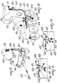
- the reference numeral 201 designates a braking device according to a fourth aspect of the invention, applied to a skate 202.
- the skate 202 comprises a shoe 203 which is composed of a quarter 204 which surrounds the rear lateral region of the user's leg and is articulated to a shell 205 with which a frame 206 is associated in a lower region.
- the frame 206 has a cross-section shaped like an inverted U and supports one or more wheels which are designated by the reference numeral 207 and may be mutually aligned.
- Conventional levers 208 may be applied for the securing of the quarter 204 and of the shell 205.
- the braking device comprises at least one traction element, generally designated by the reference numeral 209, which is preferably constituted by a cable, a first end 210 whereof is arranged to the rear of the quarter 204 and is associated with a means 211 for taking up the working length of the cable.
- the means 211 is associated with the quarter 204 in a rearward region.
- the means for taking up the working length of the cable can be constituted, for example, by a cylindrical knob 212 which is arranged longitudinally with respect to the quarter 204 and has a threaded axial seat for a complementarily threaded stop element which is associated with the first end 210 of the cable 209, which can thus be taken up or released by means of a rotation imparted to said knob 212.
- the cable is slidingly associated with an adapted sheath 213 which runs in a rearward region, internally or externally, with respect to the quarter 204 and to the shell 205 until it arrives below the sole 214.
- the second end 215 of the cable has a stop element 216 which is accommodated at an adapted first seat 217 formed at a braking element 218 which is pivoted, by means of a pivot 219, between the wings of the frame 206 in a region above the space between two mutually adjacent wheels 207.
- the braking element 218 has, in a transverse cross-section, an arched shape with concavities directed toward the wheels 207.
- the first seat 217 is formed on a plane of arrangement which lies above the plane of arrangement of the pivot 219 and in a more rearward position, so that traction applied by the cable is matched by the approach of an adapted first slot 220, formed to the rear of said braking element 218, toward the rolling surface of one of the wheels.
- a second slot 221 which is such as to allow non-interaction with the adjacent wheel 207.
- the braking element 218 is kept in neutral position, so that the first and second slots 220 and 221 do not interact with the wheels, by means of an adapted first spring 222.
- Activation of the braking element occurs, in this embodiment, following a forward tilting of the quarter 204 beyond a given rotation angle which can be selected for example by virtue of the means 211 for taking up the working length of the traction element.
- a backward rotation imparted by the user to said quarter 204 is in fact followed by a traction imparted to the cable which rotates the braking element so that the first slot 220 interacts with the rolling surface of the underlying wheel 207.
- the presence of the means 211 thus allows both to compensate any wear of the wheel and to vary the extent of the tilt of the quarter before which interaction with the first slot 220 occurs.
- the first spring 222 allows the braking element to return to its initial neutral position.
- Figures 10-15 illustrate a further embodiment for a braking device 401 in which the traction element 409 is again constituted by a cable, the first end 410 whereof is arranged to the rear of the quarter 404 and is associated with a means 411 for taking up the working length of the cable.
- the means 411 for taking up the useful length of the cable is preferably constituted by a cylindrical knob 412 which can be activated by the user.
- the cable is associated at an adapted sheath 413 which runs to the rear, internally or externally, with respect to the quarter 404 and to the shell 405 until it arrives below the sole 414.
- the cable 409 is connected, at its second end 415, to a braking element 418 which is constituted by a pad which is preferably shaped like a parallelepiped with a rectangular base and is pivoted between the wings of the frame 406 at a first pivot 419 which is located in the interspace between two mutually adjacent wheels 407.
- a braking element 418 which is constituted by a pad which is preferably shaped like a parallelepiped with a rectangular base and is pivoted between the wings of the frame 406 at a first pivot 419 which is located in the interspace between two mutually adjacent wheels 407.
- the braking element 418 also has a third end 424 which can oscillate freely and is arranged adjacent to the sole 414 of the shell 405.
- a slot is formed at the end, and a second pivot 425 is arranged within it; the second end 415 of the cable 409 is anchored to said second pivot.
- An elastically deformable element such as a spring 422, is also connected to the second pivot 425.
- the elastic element is rigidly coupled, at its other end, at a third pivot 426 which is arranged transversely to the lateral wings 406 or is associated below the sole 414 of the shell 405.
- a forward tilting of the quarter 404 is thus followed by traction applied to the cable 409, which makes the braking element 418 rotate with respect to the first pivot 419, so as to interact at the rolling surface of the wheel 407 arranged below the heel region.
- the spring 422 returns the braking element 418 to its neutral condition.
- a backward flexing of the quarter is instead followed by release of the cable 409 and by the rotation of the braking element 418 toward the toe of the skate by means of the spring 422.
- a surface of the braking element interacts with the rolling surface of the adjacent wheel 407.
- Figure 12 also shows a further advantage which can be obtained by the braking device: when the skate is not being worn, the spring 422 in fact forces interaction between the braking element 418 and the wheel which is adjacent thereto in the direction of the toe of the skate: this allows the user to put the skate on in an optimum manner even while resting the skate on the ground, because the interaction of the braking element with the wheel prevents the skate from moving.
- the braking device also comprises means for selecting the activation of the braking element 418 upon a forward or backward flexing of the quarter 404.
- This means is constituted by a pivot 427 which can be removably inserted at a first pair of holes 428 and at a second pair of holes 429 formed on the wings of the frame 406 in the interspace between two adjacent wheels 407 in which the braking element 418 is located and at a higher level than the first pivot 419.
- the location of said first and second pairs of holes is such as, once the pivot 427 has been inserted in one of said pairs, to limit the rotation of the braking element 418 following a given tilt.
- figure 14 illustrates the case in which the pivot 427 is inserted within the first pair of holes 428, which is adjacent to the wheel 407 which lies below the heel region.
- a forward tilt of the quarter is always followed by the rotation of the braking element 418 toward the heel of the skate, but the presence of the pivot 427 prevents interaction with the rolling surface of said wheel and thus the braking action does not occur.
- figure 15 illustrates the condition in which the pivot 427 is inserted at the second pair of holes 429, so that a backward tilt of the quarter is followed by a rotation of the braking element 418 toward the toe of the skate. This rotation, however, is limited by the presence of the pivot 427, which prevents its interaction with the wheel.
- this solution allows to achieve the intended aim and objects, with the additional advantage of allowing to achieve a braking action for both forward and backward flexing of the quarter.
- the presence of the spring 422 allows the user to put the skate on in an optimum manner, since the skate is braked.
- the materials and the dimensions which constitute the individual components of the braking device may be the most pertinent according to the specific requirements.
Landscapes
- Footwear And Its Accessory, Manufacturing Method And Apparatuses (AREA)
- Braking Arrangements (AREA)
Abstract
Description
Claims (24)
- In-line roller skate comprising a shoe (2,202) composed of a quarter (4,204,404) which is articulated to a shell (5,105,205,305,405) associated with a frame (6,106,206,306,406) for supporting a set of wheels (7,107,207,307,407), comprising a braking device having a pivoting braking element (17,120,218,332,418) adapted for selective engagement with a braking surface upon a pivoting motion of said quarter, and comprising at least one flexible traction element (9,109,209,309,409) which connects said quarter to said braking element (17,120,218,332,418) and which is slidably guided on and/or in the skate so that a pivoting motion of said quarter slidably moves said traction element resulting in a pivoting motion of said braking element which engages the braking surface.
- In-line skate according to claim 1, characterized in that said braking element is constituted by a block (20,120,218,331,418) which interacts with the ground, said block being pivoted to said frame and being connected to said at least one traction element.
- In-line skate according to claim 1, characterized in that it comprises an elastically deformable element (24,124,222,324,422) suitable to push said braking element into the inactive condition once said quarter has been returned to the position for normal use.
- In-line skate according to one or more of the preceding claims, characterized in that said at least one traction element is constituted by a cable (9), a first portion whereof surrounds said quarter (4) externally and to the rear and is associated therewith at an adapted engagement means (11), such as a rack or a toothed region arranged longitudinally and to the rear of said quarter.
- In-line skate according to claim 4, characterized in that said cable (9) passes inside said shoe (3) through an adapted pair of holes (12) formed laterally with respect to said quarter (4), a first pair of stop elements (13) for a pair of sheaths (14) for guiding said cable being associated inside said quarter, said pair of sheaths protruding below the sole (15) of said shell (5) and being locked, by means of a second pair of stop elements (16), inside wings (18) of said frame (6).
- In-line skate according to claim 5, characterized in that said braking element (17) comprises a block (20) which is articulated, by means of a pivot (21), to said frame (6) above the locking region of said pair of sheaths (14).
- In-line skate according to claim 6, characterized in that said cable has a second portion (22) which protrudes from said pair of sheaths and passes within an adapted seat (23) formed transversely to said block (20), a pair of springs (24) being interposed coaxially to said cable between said seat (23) and said second pair of stop elements (16).
- In-line skate according to one or more of the preceding claims, characterized in that said traction element comprises a sheath (114) locked, at one end, at a second pair of stop elements (116) associated at lateral wings of said frame (106), said traction element (109) having a second portion (122) which protrudes from said sheath (114) and passes within an adapted seat (123) formed transversely to a block (120), which is interposed between two mutually adjacent of said wheels (107) in the interspace between said wings of said frame and is transversely pivoted to said wings by means of a pivot (121).
- In-line skate according to claim 1, characterized in that said traction element is constituted by a cable (109), said cable being slidingly associated with an adapted sheath (114) which runs at the rear of said quarter (104) and of said shell (105) until it arrives below the sole (115), the terminal end of said cable being provided with a stop element (116) which is accommodated at an adapted second seat formed at said braking element which is pivoted transversely, by means of a pivot (121), between the wings of said frame in a region which lies above the space between two of said wheels (107) which are mutually adjacent.
- In-line skate according to one or more of the preceding claims, characterized in that said traction element (309) is guided within an adapted sheath (314) which protrudes below the sole (315) of said shell (305) and interacts with a pair of stop elements (316) which are laterally associated at the wings of said frame (306), said traction element having a second portion (322) which is rigidly associated with an adapted seat (323) formed transversely to at least one lever (331) which has an end freely pivoted, by means of a pivot (321), to said wings of said frame below said sole, a braking pad (332) being associated with the other end and interacts directly with the facing hub (333) of one of said wheels (307).
- In-line skate according to claim 10, characterized in that said seat (323) is formed in the interspace between said pivot (321) and said braking pad (332), so that traction imparted to said at least one traction element (309) is followed by direct interaction of said braking pad with said hub (333).
- In-line skate according to claim 1, characterized in that said at least one traction element is constituted by a cable (209,409), a first end (210,410) of said cable being arranged to the rear of said quarter (204,404) and being associated with a means (211,411) for taking up the working length of said cable.
- In-line skate according to claim 12, characterized in that said means is constituted by a cylindrical knob (212,412) which is arranged longitudinally to said quarter and has a threaded axial seat for a complementarily threaded stop element which is associated with said first end of said cable so that it is taken up or released when said knob is rotated.
- In-line skate according to claim 12, characterized in that said cable (209) is slidingly associated with an adapted sheath (213) which runs to the rear of said quarter (204) and said shell (205) until it arrives below said sole (214), a second end (215) of said cable having a stop element (216) which is accommodated at an adapted first seat (217) formed at a braking element (218) which is pivoted transversely, by means of a pivot (219), between the wings of said frame (206) in a region which lies above the space between two of said mutually adjacent wheels (207).
- In-line skate according to claim 14, characterized in that said braking element (218) has, in a transverse cross-section, an arched shape with concavities directed toward said wheels, said first seat (217) being formed on a plane of arrangement which is higher than that of said pivot (219) and in a more rearward position, so that traction applied by said cable is matched by an approach of an adapted first slot (220), formed to the rear on said braking element, toward the rolling surface of one of said wheels.
- In-line skate according to one or more of the preceding claims, characterized in that said braking element (218) is kept in neutral position, and thus so that said first slot (220) does not interact with one of said wheels, by an adapted first spring (222), said braking element being activated when said quarter is tilted forward beyond a given angle which can be selected through said means (211) for taking up the working length of said traction element.
- In-line skate according to one or more of the preceding claims, characterized in that a second end (415) of said traction element (409) is connected to a braking element (418) which is constituted by a pad, shaped like a parallelepiped with a rectangular base, which is pivoted between said wings of said frame (406) at a first pivot (418) arranged in the interspace between two mutually adjacent wheels (407).
- In-line skate according to claim 17, characterized in that said braking element (418) has a third end (424) which can oscillate freely and is arranged adjacent to the sole (414) of said shell (405), a slot being formed at said third end, a second pivot (425) being located at said slot, said second end (415) of said cable being anchored to said second pivot.
- In-line skate according to claim 18, characterized in that an elastically deformable element is connected to said second pivot, said element being constituted by a spring (422) which is rigidly coupled, at its other end, at said sole (414) of said shell (405) or at a third pivot (426) which is arranged transversely to said lateral wings of said frame (406).
- In-line skate according to claim 19, characterized in that the surfaces of said braking element (419), which oscillates with respect to said first pivot (419) upon a forward or backward flexing of said quarter (404), interact, beyond a given rotation angle, with the rolling surfaces of said mutually adjacent wheels (407).
- In-line skate according to claim 20, characterized in that when the skate is not being worn said elastically deformable element (422) forces said braking element (418) to rotate toward the toe of said skate so as to interact with the rolling surface of said adjacent wheel (407).
- In-line skate according to one or more of the preceding claims, characterized in that it comprises means (427) for selecting the activation of said braking element (418) upon either a forward or backward flexing of said quarter (404).
- In-line skate according to claim 22, characterized in that said means are constituted by a pivot (427) which can be inserted in a removable manner either within a first pair (428) or a second pair (429) of holes which are formed on said wings of said frame (406) in the interspace between two adjacent wheels (407), in which said braking element is located, and at a higher level than said first pivot (419).
- In-line skate according to claim 23, characterized in that said first (428) and second (429) pairs of holes allow, once said pivot has been inserted in at least one of said pairs, to limit the rotation of said braking element (418), preventing its interaction with at least one of said wheels (407).
Applications Claiming Priority (4)
| Application Number | Priority Date | Filing Date | Title |
|---|---|---|---|
| ITTV920149 | 1992-11-30 | ||
| ITTV920151 | 1992-11-30 | ||
| IT000151 IT1257742B (en) | 1992-11-30 | 1992-11-30 | Rapid activation braking device for roller skates - has tilting of shoe rear quarter pulling cable to move pivoting braking element into ground contact |
| IT92TV149 IT1257740B (en) | 1992-11-30 | 1992-11-30 | Rapid activation braking device for roller skates - has tilting of shoe rear quarter pulling cable to move pivoting braking element into ground contact |
Publications (2)
| Publication Number | Publication Date |
|---|---|
| EP0600274A1 EP0600274A1 (en) | 1994-06-08 |
| EP0600274B1 true EP0600274B1 (en) | 1998-04-29 |
Family
ID=26332435
Family Applications (1)
| Application Number | Title | Priority Date | Filing Date |
|---|---|---|---|
| EP93118202A Expired - Lifetime EP0600274B1 (en) | 1992-11-30 | 1993-11-10 | Roller skate with braking device |
Country Status (8)
| Country | Link |
|---|---|
| US (2) | US5505469A (en) |
| EP (1) | EP0600274B1 (en) |
| JP (1) | JPH06205868A (en) |
| AT (1) | ATE165523T1 (en) |
| AU (1) | AU671154B2 (en) |
| CA (1) | CA2103115A1 (en) |
| DE (1) | DE69318262T2 (en) |
| ES (1) | ES2114996T3 (en) |
Families Citing this family (33)
| Publication number | Priority date | Publication date | Assignee | Title |
|---|---|---|---|---|
| US5299815A (en) * | 1992-02-18 | 1994-04-05 | Brosnan Kelly M | Roller skate braking device |
| US6007076A (en) * | 1992-11-30 | 1999-12-28 | Nordica S.P.A, | Braking device particularly for skates |
| EP0808201A4 (en) * | 1995-02-02 | 1999-01-13 | Peter A Daley | System for actuating a skate brake |
| US6279922B1 (en) | 1999-06-04 | 2001-08-28 | Richard S. Gaster | In-line skate wheel disabling apparatus |
| US5772220A (en) | 1995-06-07 | 1998-06-30 | Gaster; Richard S. | In-line skate conversion apparatus |
| US6446982B1 (en) | 1995-06-07 | 2002-09-10 | Richard S. Gaster | In-line skate conversion apparatus |
| DE19522127A1 (en) * | 1995-06-19 | 1996-03-28 | Grabosch Reinhold | Roller skates for use at high speeds |
| US5752707A (en) * | 1995-07-28 | 1998-05-19 | David Geoffrey Peck | Cuff-activated brake for in-line roller skate |
| AU6982396A (en) * | 1995-09-25 | 1997-04-17 | Bauer Inc | In-line roller skate with brake system including a flexible brake band |
| IT1279495B1 (en) * | 1995-12-22 | 1997-12-10 | Nordica Spa | STRUCTURE OF BRAKING DEVICE, PARTICULARLY FOR SKATES |
| FR2746027B1 (en) * | 1996-03-18 | 1998-05-07 | WHEEL SKATE | |
| USD378116S (en) * | 1996-03-19 | 1997-02-18 | Far Great Plastics Industrial Co., Ltd. | Roller skate |
| FR2746663B1 (en) * | 1996-03-28 | 1998-05-29 | Rossignol Sa | ONLINE SKATE SKATE |
| FR2747049B1 (en) * | 1996-04-04 | 1998-05-29 | Rossignol Sa | ONLINE CASTER SKATE WITH AUXILIARY CHASSIS |
| US5860492A (en) * | 1996-04-29 | 1999-01-19 | Controlit, Inc. | Hand-activated brake and method |
| IT1288634B1 (en) | 1996-07-01 | 1998-09-23 | Nordica Spa | BRAKING CONTROL DEVICE PARTICULARLY FOR SKATES |
| FR2753106A1 (en) * | 1996-09-12 | 1998-03-13 | Rossignol Sa | Roller skate with wheels in line and brake |
| US5755450A (en) * | 1996-10-18 | 1998-05-26 | Reebok International Ltd. | Braking system for an in-line skate |
| US5997014A (en) * | 1996-10-18 | 1999-12-07 | Reebok International Ltd. | Braking system for an in-line skate |
| US5791664A (en) * | 1997-01-10 | 1998-08-11 | Koester, Jr.; Frank A. | Braking system for in-line skates |
| FR2758471B1 (en) * | 1997-01-20 | 1999-03-26 | Rossignol Sa | IN-LINE CASTER SKATE HAVING A BRAKE ACTING ON THE CASTERS |
| ITTV980001A1 (en) * | 1998-01-09 | 1999-07-09 | Benetton Sportsystem Spa | DEVICE FOR THE REGENERATION OF A BRAKE, ESPECIALLY FOR PATT INI |
| US6010137A (en) * | 1998-06-01 | 2000-01-04 | Rollerblade, Inc. | Quick adjusting braking apparatus |
| US5908197A (en) * | 1998-06-10 | 1999-06-01 | Strothmann; Achim | Braking assembly for an in-line roller skate |
| DE69918226T2 (en) * | 1998-07-21 | 2005-08-25 | Rollerblade S.R.L. | Roller skate with a braking device |
| US6425586B1 (en) * | 1998-12-30 | 2002-07-30 | Benetton Group S.P.A. | Braking device particularly for skates |
| US6227551B1 (en) * | 1999-06-04 | 2001-05-08 | 9084-6593 Quebec Inc. | In-line roller skate with eccentrically pivot wheel frames |
| US6254109B1 (en) * | 2000-03-20 | 2001-07-03 | Azor Horton | Anti-lock braking system for rollerblades |
| US6478312B1 (en) | 2000-06-23 | 2002-11-12 | Gary M. Petrucci | Brake system for a wheeled article |
| WO2002089932A1 (en) | 2001-05-03 | 2002-11-14 | Arben Vrapi | Roller skate dynamic braking system |
| US6666462B2 (en) * | 2001-12-07 | 2003-12-23 | Alron | Brake for inline skates |
| US7455305B2 (en) * | 2005-12-12 | 2008-11-25 | Alex Bellehumeur, Trustee of the Alex Bellehumeur Family Trust dated August 24, 1988 | Vertically reciprocating skate brake |
| US8556274B2 (en) | 2012-02-03 | 2013-10-15 | Craig Melvin Ellis | Skate brake |
Family Cites Families (59)
| Publication number | Priority date | Publication date | Assignee | Title |
|---|---|---|---|---|
| DE215734C (en) | 1900-01-01 | |||
| US182835A (en) | 1876-10-03 | Improvement in parlor-skates | ||
| DE223485C (en) | ||||
| DE69853C (en) | R. CZYGAN, Pfarrer, in Hermeskeil | Wheel | ||
| DE100282C (en) | ||||
| US906281A (en) | 1907-12-24 | 1908-12-08 | James Leonard Plimpton | Roller-skate. |
| US926646A (en) | 1908-04-24 | 1909-06-29 | Bicycle Skate And Mfg Co | Skate. |
| US920848A (en) | 1908-06-09 | 1909-05-04 | Bicycle Skate & Mfg Co | Roller-skate. |
| US979169A (en) * | 1909-01-16 | 1910-12-20 | Andrew J Kennedy | Skate. |
| US1050490A (en) | 1909-12-22 | 1913-01-14 | Reinhold Schwarz | Roller-skate. |
| US1379250A (en) | 1916-11-15 | 1921-05-24 | Clark Pedmobile Corp | Skate |
| FR487584A (en) | 1916-11-15 | 1918-07-12 | Charles Haskell Clark | Improvements to the skates |
| US1402010A (en) | 1920-03-05 | 1922-01-03 | Perley L Ormiston | Roller skate |
| US1371623A (en) | 1920-04-28 | 1921-03-15 | Ickenroth Anthony | Roller-skate brake |
| US1456881A (en) | 1921-06-27 | 1923-05-29 | William O Carley | Pavement glide |
| US1445048A (en) * | 1921-12-06 | 1923-02-13 | Frederick B Spross | Roller skate |
| US1524286A (en) | 1921-12-06 | 1925-01-27 | Julien A Bried | Brake for roller skates |
| GB203813A (en) | 1922-06-21 | 1923-09-20 | William George Darrington | Improvements in or relating to roller, cycle or other skates and the like |
| US1497224A (en) | 1922-06-30 | 1924-06-10 | Perley L Ormiston | Skate |
| GB243560A (en) * | 1925-01-15 | 1925-12-03 | Sunbeam Motor Car Co Ltd | Improvements in carburettors for internal combustion engines |
| DE438462C (en) | 1925-01-24 | 1926-12-15 | William George Darrington | Roller skate with a bracket on the lower leg to apply a brake |
| US1687739A (en) * | 1927-03-19 | 1928-10-16 | Walter A Slusher | Roller skate |
| US1801205A (en) | 1930-05-22 | 1931-04-14 | Edward M Mirick | Skate |
| FR791911A (en) | 1935-06-29 | 1935-12-19 | Roller Skate Improvements | |
| US2179592A (en) | 1939-02-24 | 1939-11-14 | Theodore R Goettie | Roller skate brake |
| GB609453A (en) | 1946-03-14 | 1948-09-30 | Sonti Venkata Ramaniah | Improvements in or relating to roller skates |
| DE857006C (en) | 1950-11-22 | 1952-11-27 | Carl Dipl-Ing Klaas | Two-wheeled scooter, consisting of two running wheels arranged one behind the other in the same direction with a foot-length or greater distance |
| US3288251A (en) | 1965-05-18 | 1966-11-29 | Sakwa Paul | Skateboard brake |
| GB1161623A (en) | 1967-03-03 | 1969-08-13 | Christina Melrose | An Improved Roller Skate |
| US3767220A (en) * | 1972-03-13 | 1973-10-23 | R Peterson | Foot worn two-wheeled vehicle |
| JPS5724655B2 (en) | 1972-05-24 | 1982-05-25 | ||
| FR2212162B3 (en) | 1973-01-02 | 1976-01-09 | Legros Rene Fr | |
| FR2228511A2 (en) | 1973-05-07 | 1974-12-06 | Legros Rene | Roller skates of reduced width and with brakes - wheels under chassis reduce width; has foot operated brake blocks |
| AT339795B (en) | 1975-08-25 | 1977-11-10 | Andorsen John Peter | DEVICE FOR BRAKING SKIERS AND SIMILAR TRAVEL EQUIPMENT |
| DE2800695A1 (en) | 1976-01-14 | 1978-08-03 | Otmar Fuss | Roller skate with heel operated brake - has long wheelbase with rear wheels behind heel to ensure stability |
| DE2730235A1 (en) | 1976-01-14 | 1979-03-29 | Otmar Fuss | Roller skate with brake - is operated by movement exerted on heel area of skate tread surface acting to stop movement |
| FR2358907A1 (en) | 1976-07-22 | 1978-02-17 | Guillou Jean Claude | Roller skate or skateboard - has large dia. narrow wheel at each end, with suspension system and brake shoe engaging ground when board is tilted |
| US4088334A (en) | 1977-03-25 | 1978-05-09 | Johnson Elmer E | Skateboard brake |
| US4168076A (en) | 1978-06-14 | 1979-09-18 | Johnson Noel K | Skateboard with tail brake |
| BE868847A (en) | 1978-07-07 | 1979-01-08 | Anbergen Eric | SKATEBOARD IMPROVEMENTS |
| DE2925555C2 (en) | 1979-06-25 | 1983-11-24 | Otto Dipl.-Ing. 8951 Unterthingau Lachner | Single track, steerable roller skate |
| US4275895A (en) | 1980-01-24 | 1981-06-30 | Edwards Jesse O | Roller skate brake |
| US4300781A (en) * | 1980-01-28 | 1981-11-17 | Riggs Dennis D | Roller skate braking system |
| DE8119669U1 (en) | 1981-07-06 | 1982-03-04 | Niemann, Werner, 4900 Herford | Single track roller skates with brakes |
| EP0243560A1 (en) | 1986-04-30 | 1987-11-04 | Jean-Jaques Osaer | Braking device for roller skates |
| FR2622119B1 (en) * | 1987-10-23 | 1990-09-07 | Murga Jose | CASTER SKATE HAVING AT LEAST TWO CASTERS MOUNTED IN A MEDIAN PLAN |
| IT215558Z2 (en) | 1989-01-27 | 1990-10-10 | Olivieri Icaro & C | WHEEL SHOE WITH BRAKING DEVICE. |
| US5052701A (en) * | 1989-08-23 | 1991-10-01 | Rollerblade, Inc. | Roller skate with pivoting brake |
| US4943072A (en) * | 1989-08-24 | 1990-07-24 | Sy Henig | Side-actuated braking system for paired, wheeled, foot vehicles |
| FR2666239B1 (en) | 1990-09-04 | 1994-08-12 | Cros Michel | DEVICE WITH TWO RUNNING FOOTWEAR FOR INDIVIDUALLY MOVING. |
| US5088748A (en) * | 1990-12-28 | 1992-02-18 | Design Continuum Inc. | Anti-lock braking system for skates |
| US5253882A (en) * | 1992-02-04 | 1993-10-19 | Out Of Line Sports, Inc. | Hand activated skate brake and method |
| US5211409A (en) * | 1992-02-04 | 1993-05-18 | Out Of Line Sports, Inc. | Mechanically activated skate brake and method |
| ATE163363T1 (en) * | 1992-04-29 | 1998-03-15 | Benetton Sportsystem Spa | ROLLER SKATE WITH BRAKE DEVICE |
| ES2092169T3 (en) * | 1992-04-29 | 1996-11-16 | Nordica Spa | BRAKING DEVICE FOR SKATES. |
| IT1257723B (en) * | 1992-10-21 | 1996-02-13 | Nordica Spa | BRAKING DEVICE STRUCTURE, PARTICULARLY FOR SKATES |
| US5232231A (en) * | 1992-08-12 | 1993-08-03 | Bruce Carlsmith | Brake for roller skates |
| ATE130777T1 (en) * | 1992-09-01 | 1995-12-15 | Nordica Spa | BRAKE DEVICE ESPECIALLY FOR ROLLER SKATES. |
| AU672038B2 (en) * | 1992-10-23 | 1996-09-19 | Nordica S.P.A. | Braking device particularly for skates |
-
1993
- 1993-11-10 ES ES93118202T patent/ES2114996T3/en not_active Expired - Lifetime
- 1993-11-10 DE DE69318262T patent/DE69318262T2/en not_active Expired - Fee Related
- 1993-11-10 AT AT93118202T patent/ATE165523T1/en not_active IP Right Cessation
- 1993-11-10 EP EP93118202A patent/EP0600274B1/en not_active Expired - Lifetime
- 1993-11-15 CA CA002103115A patent/CA2103115A1/en not_active Abandoned
- 1993-11-18 AU AU50795/93A patent/AU671154B2/en not_active Ceased
- 1993-11-24 US US08/158,113 patent/US5505469A/en not_active Expired - Lifetime
- 1993-11-29 JP JP5298635A patent/JPH06205868A/en active Pending
-
1996
- 1996-04-05 US US08/628,254 patent/US5769433A/en not_active Expired - Fee Related
Also Published As
| Publication number | Publication date |
|---|---|
| ATE165523T1 (en) | 1998-05-15 |
| DE69318262T2 (en) | 1998-08-27 |
| US5769433A (en) | 1998-06-23 |
| CA2103115A1 (en) | 1994-05-31 |
| US5505469A (en) | 1996-04-09 |
| EP0600274A1 (en) | 1994-06-08 |
| AU671154B2 (en) | 1996-08-15 |
| AU5079593A (en) | 1994-06-09 |
| JPH06205868A (en) | 1994-07-26 |
| DE69318262D1 (en) | 1998-06-04 |
| ES2114996T3 (en) | 1998-06-16 |
Similar Documents
| Publication | Publication Date | Title |
|---|---|---|
| US5769433A (en) | Braking device particularly for skates | |
| EP0568878B1 (en) | Skate with braking device | |
| EP0610652B1 (en) | Skate | |
| CA2108595C (en) | Braking device particularly for skates | |
| EP0656220B1 (en) | In-line skate | |
| EP0567948B1 (en) | Braking device on a roller skate | |
| US5590889A (en) | Braking device particularly for skates | |
| EP0599043B1 (en) | Braking device on a rollerskate | |
| US5511804A (en) | Braking device, particularly for skates | |
| EP1016436B1 (en) | Braking device particularly for skates | |
| EP0681857B1 (en) | Braking device particularly for skates | |
| EP0694321B1 (en) | Braking device for skates | |
| EP0685245B1 (en) | Skate with a braking device | |
| EP0613705B1 (en) | Roller skate with braking device | |
| US6007076A (en) | Braking device particularly for skates | |
| EP0681856B1 (en) | Skate with a braking device |
Legal Events
| Date | Code | Title | Description |
|---|---|---|---|
| PUAI | Public reference made under article 153(3) epc to a published international application that has entered the european phase |
Free format text: ORIGINAL CODE: 0009012 |
|
| AK | Designated contracting states |
Kind code of ref document: A1 Designated state(s): AT BE CH DE ES FR GB IT LI NL |
|
| RAP3 | Party data changed (applicant data changed or rights of an application transferred) |
Owner name: NORDICA S.P.A |
|
| 17P | Request for examination filed |
Effective date: 19941125 |
|
| 17Q | First examination report despatched |
Effective date: 19950517 |
|
| GRAG | Despatch of communication of intention to grant |
Free format text: ORIGINAL CODE: EPIDOS AGRA |
|
| GRAG | Despatch of communication of intention to grant |
Free format text: ORIGINAL CODE: EPIDOS AGRA |
|
| GRAH | Despatch of communication of intention to grant a patent |
Free format text: ORIGINAL CODE: EPIDOS IGRA |
|
| RAP1 | Party data changed (applicant data changed or rights of an application transferred) |
Owner name: BENETTON SPORTSYSTEM S.P.A. |
|
| GRAH | Despatch of communication of intention to grant a patent |
Free format text: ORIGINAL CODE: EPIDOS IGRA |
|
| GRAA | (expected) grant |
Free format text: ORIGINAL CODE: 0009210 |
|
| AK | Designated contracting states |
Kind code of ref document: B1 Designated state(s): AT BE CH DE ES FR GB IT LI NL |
|
| PG25 | Lapsed in a contracting state [announced via postgrant information from national office to epo] |
Ref country code: NL Free format text: LAPSE BECAUSE OF FAILURE TO SUBMIT A TRANSLATION OF THE DESCRIPTION OR TO PAY THE FEE WITHIN THE PRESCRIBED TIME-LIMIT Effective date: 19980429 Ref country code: BE Free format text: LAPSE BECAUSE OF FAILURE TO SUBMIT A TRANSLATION OF THE DESCRIPTION OR TO PAY THE FEE WITHIN THE PRESCRIBED TIME-LIMIT Effective date: 19980429 |
|
| REF | Corresponds to: |
Ref document number: 165523 Country of ref document: AT Date of ref document: 19980515 Kind code of ref document: T |
|
| REG | Reference to a national code |
Ref country code: CH Ref legal event code: EP |
|
| REF | Corresponds to: |
Ref document number: 69318262 Country of ref document: DE Date of ref document: 19980604 |
|
| REG | Reference to a national code |
Ref country code: ES Ref legal event code: FG2A Ref document number: 2114996 Country of ref document: ES Kind code of ref document: T3 |
|
| ET | Fr: translation filed | ||
| ITF | It: translation for a ep patent filed | ||
| NLV1 | Nl: lapsed or annulled due to failure to fulfill the requirements of art. 29p and 29m of the patents act | ||
| PG25 | Lapsed in a contracting state [announced via postgrant information from national office to epo] |
Ref country code: GB Free format text: LAPSE BECAUSE OF NON-PAYMENT OF DUE FEES Effective date: 19981110 |
|
| PLBE | No opposition filed within time limit |
Free format text: ORIGINAL CODE: 0009261 |
|
| STAA | Information on the status of an ep patent application or granted ep patent |
Free format text: STATUS: NO OPPOSITION FILED WITHIN TIME LIMIT |
|
| 26N | No opposition filed | ||
| GBPC | Gb: european patent ceased through non-payment of renewal fee |
Effective date: 19981110 |
|
| PGFP | Annual fee paid to national office [announced via postgrant information from national office to epo] |
Ref country code: DE Payment date: 20081126 Year of fee payment: 16 |
|
| PGFP | Annual fee paid to national office [announced via postgrant information from national office to epo] |
Ref country code: ES Payment date: 20081107 Year of fee payment: 16 Ref country code: AT Payment date: 20081023 Year of fee payment: 16 |
|
| PG25 | Lapsed in a contracting state [announced via postgrant information from national office to epo] |
Ref country code: AT Free format text: LAPSE BECAUSE OF NON-PAYMENT OF DUE FEES Effective date: 20091110 |
|
| PG25 | Lapsed in a contracting state [announced via postgrant information from national office to epo] |
Ref country code: DE Free format text: LAPSE BECAUSE OF NON-PAYMENT OF DUE FEES Effective date: 20100601 |
|
| PGFP | Annual fee paid to national office [announced via postgrant information from national office to epo] |
Ref country code: FR Payment date: 20101217 Year of fee payment: 18 |
|
| PGFP | Annual fee paid to national office [announced via postgrant information from national office to epo] |
Ref country code: CH Payment date: 20101025 Year of fee payment: 18 |
|
| REG | Reference to a national code |
Ref country code: ES Ref legal event code: FD2A Effective date: 20110328 |
|
| PGFP | Annual fee paid to national office [announced via postgrant information from national office to epo] |
Ref country code: IT Payment date: 20101106 Year of fee payment: 18 |
|
| PG25 | Lapsed in a contracting state [announced via postgrant information from national office to epo] |
Ref country code: ES Free format text: LAPSE BECAUSE OF NON-PAYMENT OF DUE FEES Effective date: 20110315 |
|
| PG25 | Lapsed in a contracting state [announced via postgrant information from national office to epo] |
Ref country code: ES Free format text: LAPSE BECAUSE OF NON-PAYMENT OF DUE FEES Effective date: 20091111 |
|
| REG | Reference to a national code |
Ref country code: CH Ref legal event code: PL |
|
| PG25 | Lapsed in a contracting state [announced via postgrant information from national office to epo] |
Ref country code: CH Free format text: LAPSE BECAUSE OF NON-PAYMENT OF DUE FEES Effective date: 20111130 Ref country code: LI Free format text: LAPSE BECAUSE OF NON-PAYMENT OF DUE FEES Effective date: 20111130 |
|
| REG | Reference to a national code |
Ref country code: FR Ref legal event code: ST Effective date: 20120731 |
|
| PG25 | Lapsed in a contracting state [announced via postgrant information from national office to epo] |
Ref country code: IT Free format text: LAPSE BECAUSE OF NON-PAYMENT OF DUE FEES Effective date: 20111110 |
|
| PG25 | Lapsed in a contracting state [announced via postgrant information from national office to epo] |
Ref country code: FR Free format text: LAPSE BECAUSE OF NON-PAYMENT OF DUE FEES Effective date: 20111130 |