EP0600272A1 - Electric motor, in particular commutator motor - Google Patents
Electric motor, in particular commutator motor Download PDFInfo
- Publication number
- EP0600272A1 EP0600272A1 EP93118166A EP93118166A EP0600272A1 EP 0600272 A1 EP0600272 A1 EP 0600272A1 EP 93118166 A EP93118166 A EP 93118166A EP 93118166 A EP93118166 A EP 93118166A EP 0600272 A1 EP0600272 A1 EP 0600272A1
- Authority
- EP
- European Patent Office
- Prior art keywords
- housing
- cover
- electric motor
- bottom housing
- motor according
- Prior art date
- Legal status (The legal status is an assumption and is not a legal conclusion. Google has not performed a legal analysis and makes no representation as to the accuracy of the status listed.)
- Withdrawn
Links
Images


Classifications
-
- H—ELECTRICITY
- H02—GENERATION; CONVERSION OR DISTRIBUTION OF ELECTRIC POWER
- H02G—INSTALLATION OF ELECTRIC CABLES OR LINES, OR OF COMBINED OPTICAL AND ELECTRIC CABLES OR LINES
- H02G3/00—Installations of electric cables or lines or protective tubing therefor in or on buildings, equivalent structures or vehicles
- H02G3/26—Installations of cables, lines, or separate protective tubing therefor directly on or in walls, ceilings, or floors
-
- H—ELECTRICITY
- H02—GENERATION; CONVERSION OR DISTRIBUTION OF ELECTRIC POWER
- H02K—DYNAMO-ELECTRIC MACHINES
- H02K5/00—Casings; Enclosures; Supports
- H02K5/04—Casings or enclosures characterised by the shape, form or construction thereof
- H02K5/22—Auxiliary parts of casings not covered by groups H02K5/06-H02K5/20, e.g. shaped to form connection boxes or terminal boxes
- H02K5/225—Terminal boxes or connection arrangements
Definitions
- the invention relates to an electric motor, in particular a commutator motor of the type specified in the preamble of claim 1.
- Electric motors with customer-specific connector housings arranged on the outside of the motor housings are already known, which are firmly connected to the ends of a plurality of connecting strands coming from the windings, carbon brushes and other electrical components.
- the connecting leads are led out of openings in the motor housing or the end shields, the free ends of which are connected to the connector housing.
- the individual connecting strands running outside the motor housing are loosely bundled by a cable tie. However, this does not prevent individual connecting strands from rubbing against the surfaces and sharp edges of the electric motor by shaking the electric motor and can therefore be damaged. This damage can be avoided in that the connecting strands are surrounded outside of the motor housing by a strand protection element which is supported thereon.
- This wire protection element consists of a long piece of insulating hose, which prevents damage to the connecting wire.
- the assembly of this long piece of insulating hose is very complex because the connecting strands have to be pushed through the piece of hose.
- This strand protection element also has the disadvantage that a displacement of the insulating tube piece on the connecting strands cannot be avoided. There is also no strain relief for the connecting strand.
- the invention has for its object to provide an electric motor, in particular a commutator motor, in which the outside of the motor housing led to a customer-specific connector housing easily and safely by a Wire protection element are protected, which is easy to manufacture, assemble and lock.
- an electric motor in particular a commutator motor
- the outside of the motor housing led to a customer-specific connector housing easily and safely by a Wire protection element are protected, which is easy to manufacture, assemble and lock.
- the connecting wires are protected outside the motor housing by a simple and easy-to-install wire protection element.
- this strand protection element can be fixed in position at the same time by clamping only one connection strand in the strand protection element.
- the strand protection element can also be reused at any time due to its disassembly.
- FIG. 1 shows a commutator motor 1 with a customer-specific connector housing 5 arranged on the outside of the motor housing 3, which is firmly connected to the ends of a plurality of connecting leads 11 coming from the windings, carbon brushes 7, 9 and other electrical components.
- the motor housing 3 consists, in a known manner, of a cylindrical casing housing part and of open bearing plates arranged on the end face thereof which only one end shield 13 is shown in FIG.
- This end shield 13 has an outer ring 15 to be connected to the casing housing part, which is fixedly connected via connecting struts 17, 19, 21, 23 to a centrally arranged bearing part 25 for the rotor shaft.
- the connecting strands 11 are led out of an opening 26 between the connecting struts 19 and 21 and extend outside the motor housing 3 or the end shield 13 to the plug housing 5.
- a wire protection element 27 In order to rub the connecting strands 11 against the edges and / or the surface of the end shield 13 or To prevent the motor housing 3, the parts of the connecting wire 11 extending outside the motor housing are surrounded by a wire protection element 27.
- This wire protection element 27 consists of an elongated, U-shaped bottom housing 29 which can be put over the connecting wire 11 and closed by a cover 31.
- the bottom housing 29 has, in addition to a duct shaft 33 for the connecting strand 11, at least one duct compartment section 35 for a single connecting strand 37, which can be clamped by the cover 31 which can be closed by the open longitudinal side of the U-shaped bottom housing 29.
- this cover 31 can be firmly connected to the base housing 29 by means of snap-in connections.
- the cover 31 and the base housing 29 are made from a one-piece plastic part and are firmly connected to one another via a hinge-like joint 39.
- the duct shaft section 35 is arranged for clamping the one connecting slot 37 on one side next to the duct shaft 33 in the bottom housing 29 and is arranged by a side wall 41 of the bottom housing 29 and one upright on the bottom surface 43 of the bottom housing 29 between the duct shaft section 35 and the duct shaft 33 Partition wall 45 formed.
- the bottom surface 47 in the duct shaft section 35 is arranged higher than the bottom surface 43 of the bottom housing 29 and is provided with a profile formed by longitudinal grooves 55, whereby a secure fixation of the individual terminal clip 37 to be clamped and thus the wire protection element 27 is achieved.
- the cover 31 closing the bottom housing 29 has on its inside 49 an upright pressure bar 51 which is designed to match the length of the duct shaft section 35 and through which the individual connecting slot 37 in the duct shaft section 35 can be clamped against the bottom housing 47 when the cover 31 is closed.
- the free end 53 of the pressure web 51 is rounded.
- the duct shaft section 35 and the pressure web 51 are arranged in the vicinity of the sides 41, 49 of the base housing 29 and the cover 31 connected by the hinge-like joint 39.
- the side walls 41, 59 of the bottom housing 29 have stop surfaces 61, 62, 63, 64 for stop edge surfaces 65, 66 of the cover 31 that protrude from the outside inwards at the free ends 57, 58.
- the inner edge 67 of the cover 31 bears against the stop surfaces 62, 64 when the cover 31 is closed. This ensures a secure fixation of the cover 31 on the bottom housing 29.
- the latching of the cover 31 on the bottom housing 29 takes place in that the bottom housing 29 on its side wall 59 facing away from the hinge-like hinge 39 resilient locking webs 77, 78 with locking lugs 69, 70, which behind locking lugs 71, 72 of fixed locking hooks 80, 82 can be locked on the cover 31.
- two fixed latching hooks 71, 72 on the cover 31 and two resilient latching webs 77, 78 on the bottom housing 29 are arranged on the inside in the strand protection element housing. Due to this internal latching, the lid 31 cannot be opened if, for. B. hook the resilient locking webs 77, 78 with their locking lugs 69, 70 behind a body edge of the motor housing or would be bent by shaking.
- the fixed latching hooks 71, 72 protrude inward on the side wall 73 of the cover 31 facing away from the joint 39 and opposite the inner edge 67 protruding.
- the locking lugs 69, 71 are arranged at free ends of resilient locking webs 77, 78, which are connected in one piece to the bottom 43 of the bottom housing 29 and form an air gap distance 79 from the side wall 41 of the bottom housing 29. This air gap distance 79 is somewhat larger than the width of the locking lug 69, 70.
- the cover 31 and the base housing 29 have correspondingly large openings 81, 83 in the direction of escape of the locking lugs 69, 70 and the locking hooks 71, 72.
- the resilient latching webs 77, 78 can be pivoted in such a way that their latching lugs 69, 70 can be developed by the latching hooks 71, 72.
- the parallel and mutually arranged outer and inner long side walls 73, 41, 59, 49 of the bottom housing 29 and the cover 31 have a shape that is approximately matched to the outer contour of the end shield 13 or the motor housing 3. This is achieved in that the outer and inner long side walls 73, 41, 59, 49 of the bottom housing 29 and the cover 31 in the central region consist of straight side surfaces 85, 87, 89, 91, to which end side surfaces angled toward the motor housing 3 Connect 93, 95, 97, 99, 101, 103, 105, 107. As a result, the connecting strands 11 are guided closely along the outer circumference of the motor housing 3.
- the hinge-like hinge 39 is firmly connected to the long straight side surfaces 87, 89 of the bottom housing 29 and the cover 31.
- the channel section 35 and the pressure web 51 are also arranged in the region of the straight outer long side surfaces 87, 89.
- the wire protection element 27 consists of a simple and easy-to-assemble component which is clamped only one connecting wire is axially fixed in position during assembly of the wire protection element.
- the wire protection element 27 can also be used with a different number of connecting wires to be protected.
- connecting strands can subsequently be introduced into the strand protection element 27, since the strands only have to be inserted after opening the cover.
Abstract
Description
Die Erfindung betrifft einen Elektromotor, insbesondere einen Kommutatormotor der im Oberbegriff des Patentanspruchs 1 angegebenen Art.The invention relates to an electric motor, in particular a commutator motor of the type specified in the preamble of
Es sind bereits Elektromotore mit außen an den Motorgehäusen angeordneten kundenabhängigen Steckergehäusen bekannt, welche mit den Enden von mehreren von den Wicklungen, Kohlebürsten und sonstigen elektrischen Bauelementen kommenden Anschlußlitzen fest verbunden sind. Hierbei werden die Anschlußlitze aus Öffnungen der Motorgehäuse bzw. der Lagerschilde herausgeführt, wobei deren freie Enden mit dem Steckergehäuse verbunden sind. Bei bekannten Elektromotoren werden die außerhalb des Motorgehäuses verlaufenden, einzelnen Anschlußlitze durch einen Kabelbinder lose gebündelt. Hierbei wird aber nicht vermieden, daß einzelne Anschlußlitze durch Rütteln des Elektromotors an den Oberflächen und scharfen Kanten des Elektromotors reiben und daher beschädigt werden können. Diese Beschädigung kann dadurch vermieden werden, daß die Anschlußlitze außerhalb des Motorgehäuses von einem an diesem sich abstützenden Litzenschutzelement umgeben sind. Dieses Litzenschutzelement besteht aus einem langen Isolierschlauchstück, welches eine Beschädigung der Anschlußlitze verhindert. Die Montage dieses langen Isolierschlauchstückes ist aber sehr aufwendig, da die Anschlußlitze durch das Schlauchstück geschoben werden müssen. Dieses Litzenschutzelement hat außerdem den Nachteil , daß eine Verschiebung des Isolierschlauchstückes auf den Anschlußlitzen nicht vermieden werden kann. Auch ist eine Zugentlastung der Anschlußlitze hierbei nicht gegeben.Electric motors with customer-specific connector housings arranged on the outside of the motor housings are already known, which are firmly connected to the ends of a plurality of connecting strands coming from the windings, carbon brushes and other electrical components. Here, the connecting leads are led out of openings in the motor housing or the end shields, the free ends of which are connected to the connector housing. In known electric motors, the individual connecting strands running outside the motor housing are loosely bundled by a cable tie. However, this does not prevent individual connecting strands from rubbing against the surfaces and sharp edges of the electric motor by shaking the electric motor and can therefore be damaged. This damage can be avoided in that the connecting strands are surrounded outside of the motor housing by a strand protection element which is supported thereon. This wire protection element consists of a long piece of insulating hose, which prevents damage to the connecting wire. The assembly of this long piece of insulating hose is very complex because the connecting strands have to be pushed through the piece of hose. This strand protection element also has the disadvantage that a displacement of the insulating tube piece on the connecting strands cannot be avoided. There is also no strain relief for the connecting strand.
Der Erfindung liegt die Aufgabe zugrunde, einen Elektromotor, insbesondere einen Kommutatormotor zu schaffen, bei dem die außerhalb des Motorgehäuses zu einem kundenspezifischen Steckergehäuse geführten Anschlußlitze einfach und sicher durch ein Litzenschutzelement geschützt werden, welches einfach herstell-, montier- und arretierbar ist. Diese Aufgabe wird durch die im Patentanspruch 1 gekennzeichnete Erfindung gelöst.The invention has for its object to provide an electric motor, in particular a commutator motor, in which the outside of the motor housing led to a customer-specific connector housing easily and safely by a Wire protection element are protected, which is easy to manufacture, assemble and lock. This object is achieved by the invention characterized in
Die Anschlußlitze werden außerhalb des Motorgehäuses durch ein einfaches und leicht zu montierendes Litzenschutzelement sicher geschützt. Außerdem kann durch Festklemmen nur eines Anschlußlitzes in dem Litzenschutzelement dieses Litzenschutzelement gleichzeitig in seiner Lage fixiert werden. Weiterhin kann das Litzenschutzelement aufgrund seiner Demontage auch jederzeit wiederverwendet werden.The connecting wires are protected outside the motor housing by a simple and easy-to-install wire protection element. In addition, this strand protection element can be fixed in position at the same time by clamping only one connection strand in the strand protection element. Furthermore, the strand protection element can also be reused at any time due to its disassembly.
Weitere vorteilhafte Ausgestaltungen des Erfindungsgegenstandes sind den weiteren Unteransprüchen zu entnehmen.Further advantageous refinements of the subject matter of the invention can be found in the further subclaims.
Die Erfindung wird anhand eines Ausführungsbeispiels im folgenden näher beschrieben. Es zeigen:
Figur 1- eine Seitenansicht auf einen Kommutatormotor,
- Figur 2
- das Litzenschutzelement mit aufgeklapptem Deckel,
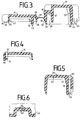
- Figur 3
- einen Schnitt durch das Litzenschutzelement in aufgeklappter Darstellung und
- Figuren 4 bis 6
- Einzelheiten aus Figur 3.
- Figure 1
- a side view of a commutator motor,
- Figure 2
- the wire protection element with the lid open,
- Figure 3
- a section through the wire protection element in an unfolded view and
- Figures 4 to 6
- Details from FIG. 3.
Die Figur 1 zeigt einen Kommutatormotor 1 mit einem außen an dem Motorgehäuse 3 angeordneten, kundenabhängigen Steckergehäuse 5, welches mit den Enden von mehreren von den Wicklungen, Kohlebürsten 7, 9 und sonstigen elektrischen Bauelementen kommenden Anschlußlitzen 11 fest verbunden ist. Das Motorgehäuse 3 besteht in bekannter Weise aus einem zylindrischen Mantelgehäuseteil und stirnseitig an diesem angeordneten, offenen Lagerschilden, von denen in der Figur 1 nur ein Lagerschild 13 dargestellt ist. Dieses Lagerschild 13 weist einen mit dem Mantelgehäuseteil zu verbindenden Außenring 15 auf, welcher über Verbindungsstreben 17, 19, 21, 23 mit einemzentrisch angeordneten Lagerteil 25 für die Rotorwelle fest verbunden ist. Die Anschlußlitze 11 werden aus einer Öffnung 26 zwischen den Verbindungsstreben 19 und 21 herausgeführt und verlaufen außerhalb des Motorgehäuses 3 bzw. des Lagerschildes 13 zu dem Steckergehäuse 5. Um ein Reiben der Anschlußlitze 11 an den Kanten und/oder der Oberfläche des Lagerschildes 13 bzw. des Motorgehäuses 3 zu verhindern, werden die außerhalb des Motorgehäuses verlaufenden Teile der Anschlußlitze 11 von einem Litzenschutzelement 27 umgeben. Dieses Litzenschutzelement 27 besteht aus einem länglichen, U-förmigen Bodengehäuse 29, welches über die Anschlußlitze 11 stülp- und durch einen Deckel 31 verschließbar ist. Das Bodengehäuse 29 weist neben einem Kanalschacht 33 für die Anschlußlitze 11 mindestens einen Kanalschachtabschnitt 35 für einen einzelnen Anschlußlitz 37 auf, welches durch den die offene Längsseite des U-förmigen Bodengehäuses 29 verschließbaren Deckel 31 festklemmbar ist. Dieser Deckel 31 ist übrigens mittels Rastverbindungen mit dem Bodengehäuse 29 fest verbindbar. Übrigens sind der Deckel 31 und das Bodengehäuse 29 aus einem einstückigen Kunststoffteil hergestellt und über ein filmscharnierartiges Gelenk 39 fest miteinander verbunden. Der Kanalschachtabschnitt 35 ist zum Festklemmen des einen Anschlußlitzes 37 an einer Seite neben dem Kanalschacht 33 in dem Bodengehäuse 29 angeordnet und wird durch eine Seitenwand 41 des Bodengehäuses 29 und einer aufrecht auf der Bodenfläche 43 des Bodengehäuses 29 zwischen dem Kanalschachtabschnitt 35 und dem Kanalschacht 33 angeordneten Zwischenwand 45 gebildet. Die Bodenfläche 47 in dem Kanalschachtabschnitt 35 ist gegenüber der Bodenfläche 43 des Bodengehäuses 29 erhöht angeordnet und ist mit einer durch Längsrillen 55 gebildeten Profilierung versehen, wodurch eine sichere Fixierung des einzelnen, festzuklemmenden Anschlußlitzes 37 und damit des Litzenschutzelementes 27 erzielt wird.FIG. 1 shows a
Der das Bodengehäuse 29 verschließende Deckel 31 weist auf seiner Innenseite 49 einen aufrecht angeordneten und einen der Länge des Kanalschachtabschnittes 35 entsprechend ausgebildeten Drucksteg 51 auf, durch welchen der einzelne Anschlußlitz 37 in dem Kanalschachtabschnitt 35 beim Verschließen des Deckels 31 gegen das Bodengehäuse 47 festklemmbar ist. Um eine Beschädigung des festzuklemmenden Anschlußlitzes 37 zu verhindern, ist das freie Ende 53 des Drucksteges 51 abgerundet ausgebildet. In vorteilhafter Ausgestaltung sind der Kanalschachtabschnitt 35 und der Drucksteg 51 in Nähe der durch das filmscharnierartige Gelenk 39 verbundenen Seiten 41, 49 des Bodengehäuses 29 und des Deckels 31 angeordnet. Die Seitenwände 41, 59 des Bodengehäuses 29 weisen an den freien Enden 57, 58 von außen nach innen einspringede Anschlagflächen 61, 62, 63, 64 für Anschlagrandflächen 65, 66 des Deckels 31 auf. Der innere Rand 67 des Deckels 31 liegt hierbei an den Anschlagflächen 62, 64 an, wenn der Deckel 31 verschlossen ist. Hierdurch wird eine sichere Fixierung des Deckels 31 auf dem Bodengehäuse 29 gewährleistet.The
Die Verrastung des Deckels 31 auf dem Bodengehäuse 29 erfolgt dadurch, daß das Bodengehäuse 29 an seiner dem filmscharnierartigen Gelenk 39 abgewandten Seitenwand 59 federnde Raststege 77, 78 mit Rastnasen 69, 70 auf, welche hinter Rastnasen 71, 72 von fest angeordneten Rasthaken 80, 82 an dem Deckel 31 verrastbar sind.The latching of the
Gemäß der Figur 2 sind zwei feste Rasthaken 71, 72 an dem Deckel 31 und zwei federnde Raststege 77, 78 an dem Bodengehäuse 29 innenliegend in dem Litzenschutzelementgehäuse angeordnet. Durch diese innenliegende Verrastung kann es nicht zu einem Öffnen des Deckels 31 kommen, wenn z. B. die federnden Raststege 77, 78 mit ihren Rastnasen 69, 70 hinter einer Körperkante des Motorgehäuses unterhaken oder durch Rütteln aufgebogen werden würden. Die festen Rasthaken 71, 72 sind an der dem Gelenk 39 abgewandten Seitenwand 73 des Deckels 31 nach innen ragend und gegenüber dem inneren Rand 67 hervorstehend ausgebildet. Die Rastnasen 69, 71 sind an freien Enden von federnden Raststegen 77, 78 angeordnet, welche einstückig mit dem Boden 43 des Bodengehäuses 29 verbunden sind und zu der Seitenwand 41 des Bodengehäuses 29 einen Luftspaltabstand 79 bilden. Dieser Luftspaltabstand 79 ist etwas größer als die Breite der Rastnase 69, 70.According to FIG. 2, two fixed
Um das Litzenschutzelement 27 wieder verwenden zu können, ist es erforderlich, daß die Rastverbindung zwischen dem Deckel 31 und dem Bodengehäuse 29 aufgehoben wird. Zu diesem Zweck weisen der Deckel 31 und das Bodengehäuse 29 in Fluchtrichtung der Rastnasen 69, 70 und der Rasthaken 71, 72 entsprechend groß ausgebildete Durchbrüche 81, 83 auf. Mittels eines durch die Durchbrüche 81, 83 hindurchsteckbaren Schraubendreher sind die federnden Raststege 77, 78 derart verschwenkbar, daß deren Rastnasen 69, 70 von den Rasthaken 71, 72 entwickelbar sind.In order to be able to use the
Die parallel zueinander angeordneten äußeren und inneren langen Seitenwände 73, 41, 59, 49 des Bodengehäuses 29 und des Deckels 31 weisen eine der Außenkontur des Lagerschildes 13 bzw. des Motorgehäuses 3 annähernd angepaßte Formen auf. Dieses wird dadurch erreicht, daß die äußeren und inneren langen Seitenwände 73, 41, 59, 49 des Bodengehäuses 29 und des Deckels 31 im mittleren Bereich aus geraden Seitenflächen 85, 87, 89, 91 bestehen, an welche sich zum Motorgehäuse 3 hin abgewinkelte Endseitenflächen 93, 95, 97, 99, 101, 103, 105, 107 anschließen. Hierdurch werden die Anschlußlitze 11 eng an dem Außenumfang des Motorgehäuses 3 entlanggeführt. Das filmscharnierartige Gelenk 39 ist übrigens mit den den langen geraden Seitenflächen 87, 89 des Bodengehäuses 29 und des Deckels 31 fest verbunden. Auch sind der Kanalabschnitt 35 und der Drucksteg 51 im Bereich der geraden äußeren langen Seitenflächen 87, 89 angeordnet.The parallel and mutually arranged outer and inner
Das erfindungsgemäße Litzenschutzelement 27 besteht aus einem einfachen und leicht zu montierenden Bauteil, das durch Klemmen nur einer Anschlußlitze bei der Montage des Litzenschutzelementes in seiner Lage axial fixiert wird. Auch kann das Litzenschutzelement 27 bei einer unterschiedlichen Anzahl von zu schützenden Anschlußlitzen eingesetzt werden. Ebenso können nachträglich noch Anschlußlitzen in das Litzenschutzelement 27 eingebracht werden, da die Litzen nach Öffnen des Deckels nur eingelegt werden müssen.The
Claims (17)
Applications Claiming Priority (2)
| Application Number | Priority Date | Filing Date | Title |
|---|---|---|---|
| DE19924240381 DE4240381A1 (en) | 1992-12-01 | 1992-12-01 | Electric motor, especially commutator motor |
| DE4240381 | 1992-12-01 |
Publications (1)
| Publication Number | Publication Date |
|---|---|
| EP0600272A1 true EP0600272A1 (en) | 1994-06-08 |
Family
ID=6474108
Family Applications (1)
| Application Number | Title | Priority Date | Filing Date |
|---|---|---|---|
| EP93118166A Withdrawn EP0600272A1 (en) | 1992-12-01 | 1993-11-10 | Electric motor, in particular commutator motor |
Country Status (2)
| Country | Link |
|---|---|
| EP (1) | EP0600272A1 (en) |
| DE (1) | DE4240381A1 (en) |
Cited By (4)
| Publication number | Priority date | Publication date | Assignee | Title |
|---|---|---|---|---|
| EP0700807A3 (en) * | 1994-09-07 | 1998-11-04 | Delphi Automotive Systems Deutschland GmbH | Motor space box for electric parts and their cable connection |
| WO2001091268A1 (en) * | 2000-05-22 | 2001-11-29 | Siemens Aktiengesellschaft | Electromotor, in particular a commutator motor |
| DE10160268A1 (en) * | 2001-12-07 | 2003-06-26 | Daimler Chrysler Ag | Holder for cables and/or lines in vehicle has bearer on which is formed at least one conduit section of U-shaped cross-section and open at ends and on one side, pivoting cover, fixing plates |
| WO2009156212A1 (en) * | 2008-06-27 | 2009-12-30 | Robert Bosch Gmbh | Holding apparatus and electric motor equipped with the same |
Families Citing this family (1)
| Publication number | Priority date | Publication date | Assignee | Title |
|---|---|---|---|---|
| JP4250823B2 (en) * | 1999-09-16 | 2009-04-08 | アイシン精機株式会社 | DC brush motor |
Citations (3)
| Publication number | Priority date | Publication date | Assignee | Title |
|---|---|---|---|---|
| GB2125636A (en) * | 1982-08-23 | 1984-03-07 | Seeley F F Nominees | Improvements in and relating to electric motors |
| US5016842A (en) * | 1988-08-30 | 1991-05-21 | Yazaki Corporation | Protector for wire harness |
| JPH04175477A (en) * | 1990-11-09 | 1992-06-23 | Hitachi Ltd | Lead wire protection device |
Family Cites Families (2)
| Publication number | Priority date | Publication date | Assignee | Title |
|---|---|---|---|---|
| US3350586A (en) * | 1965-02-19 | 1967-10-31 | Gen Electric | Dynamoelectric machine electrical component mounting and lead securing arrangement |
| IT214920Z2 (en) * | 1988-11-04 | 1990-07-04 | Magneti Marelli Spa | BRUSH HOLDER FOR A DIRECT CURRENT ELECTRIC MACHINE IN PARTICULAR FOR THE MOTOR OF AN ELECTRIC FAN FOR COOLING THE RADIATOR OF AN INTERNAL COMBUSTION ENGINE |
-
1992
- 1992-12-01 DE DE19924240381 patent/DE4240381A1/en not_active Ceased
-
1993
- 1993-11-10 EP EP93118166A patent/EP0600272A1/en not_active Withdrawn
Patent Citations (3)
| Publication number | Priority date | Publication date | Assignee | Title |
|---|---|---|---|---|
| GB2125636A (en) * | 1982-08-23 | 1984-03-07 | Seeley F F Nominees | Improvements in and relating to electric motors |
| US5016842A (en) * | 1988-08-30 | 1991-05-21 | Yazaki Corporation | Protector for wire harness |
| JPH04175477A (en) * | 1990-11-09 | 1992-06-23 | Hitachi Ltd | Lead wire protection device |
Non-Patent Citations (1)
| Title |
|---|
| PATENT ABSTRACTS OF JAPAN vol. 16, no. 480 (M - 1321) 6 October 1992 (1992-10-06) * |
Cited By (5)
| Publication number | Priority date | Publication date | Assignee | Title |
|---|---|---|---|---|
| EP0700807A3 (en) * | 1994-09-07 | 1998-11-04 | Delphi Automotive Systems Deutschland GmbH | Motor space box for electric parts and their cable connection |
| WO2001091268A1 (en) * | 2000-05-22 | 2001-11-29 | Siemens Aktiengesellschaft | Electromotor, in particular a commutator motor |
| DE10160268A1 (en) * | 2001-12-07 | 2003-06-26 | Daimler Chrysler Ag | Holder for cables and/or lines in vehicle has bearer on which is formed at least one conduit section of U-shaped cross-section and open at ends and on one side, pivoting cover, fixing plates |
| DE10160268B4 (en) * | 2001-12-07 | 2004-12-09 | Daimlerchrysler Ag | Bracket for cables and / or wires in a vehicle |
| WO2009156212A1 (en) * | 2008-06-27 | 2009-12-30 | Robert Bosch Gmbh | Holding apparatus and electric motor equipped with the same |
Also Published As
| Publication number | Publication date |
|---|---|
| DE4240381A1 (en) | 1994-06-09 |
Similar Documents
| Publication | Publication Date | Title |
|---|---|---|
| EP3152809B1 (en) | Eletrical equipment | |
| DE2340898C2 (en) | Front cover for the housing of a miniature motor | |
| DE7617478U1 (en) | Electrical plug with non-live front | |
| DE3018119C2 (en) | Cable entry with strain relief for housings of electrical machines and devices | |
| EP0479035B1 (en) | Electric motor with connection plug | |
| DE3105602A1 (en) | STAND FOR A PERMANENTLY MAGNETIC ELECTRICAL MACHINE | |
| DE2123492A1 (en) | Electric motor | |
| EP0917276B1 (en) | Casing for an electric motor | |
| DE102018125834A1 (en) | Stator for an electrical machine and method for producing such a stator | |
| EP0600272A1 (en) | Electric motor, in particular commutator motor | |
| DE2622916C2 (en) | Electric motor | |
| DE3618177A1 (en) | BRACKET FOR AN ELECTRIC MOTOR, ESPECIALLY FOR A FAN | |
| DE3431471A1 (en) | COIL BODY AND METHOD FOR WINDING AND CIRCUITING IT WITH AN EXTERNAL CONNECTION LINE | |
| DE2839600A1 (en) | ELECTRIC MOTOR | |
| DE102019112516A1 (en) | Temperature measuring device for a stator of an electrical machine with hairpin or rod wave windings | |
| DE19532265A1 (en) | Commutator motor esp sealed construction type | |
| DE4233875C2 (en) | Holding device for the strain-relieved fastening of a supply cable in a housing opening of electrical machines | |
| EP3900157A1 (en) | Commutator motor and series of commutator motors | |
| DE2445201A1 (en) | PROTECTIVE SLEEVE OR PROTECTIVE GUIDE FOR CABLES | |
| DE3730007C2 (en) | ||
| DE202014007116U1 (en) | Electrical connectors | |
| DE3142151C2 (en) | Electrical machine with a terminal box attached to its housing | |
| DE7116508U (en) | HEAT-SHRINKABLE ENCLOSURE FOR ELECTRIC CONNECTORS | |
| DE3538942A1 (en) | Field plug for an electric motor | |
| DE7720975U1 (en) | SPLIT POLE MOTOR |
Legal Events
| Date | Code | Title | Description |
|---|---|---|---|
| PUAI | Public reference made under article 153(3) epc to a published international application that has entered the european phase |
Free format text: ORIGINAL CODE: 0009012 |
|
| AK | Designated contracting states |
Kind code of ref document: A1 Designated state(s): DE ES FR GB IT |
|
| STAA | Information on the status of an ep patent application or granted ep patent |
Free format text: STATUS: THE APPLICATION HAS BEEN WITHDRAWN |
|
| 18W | Application withdrawn |
Withdrawal date: 19941011 |