EP0599550A1 - Improved switch mechanism - Google Patents
Improved switch mechanism Download PDFInfo
- Publication number
- EP0599550A1 EP0599550A1 EP93309215A EP93309215A EP0599550A1 EP 0599550 A1 EP0599550 A1 EP 0599550A1 EP 93309215 A EP93309215 A EP 93309215A EP 93309215 A EP93309215 A EP 93309215A EP 0599550 A1 EP0599550 A1 EP 0599550A1
- Authority
- EP
- European Patent Office
- Prior art keywords
- handle
- switch
- safety interlock
- manual tool
- actuation
- Prior art date
- Legal status (The legal status is an assumption and is not a legal conclusion. Google has not performed a legal analysis and makes no representation as to the accuracy of the status listed.)
- Granted
Links
Images


Classifications
-
- F—MECHANICAL ENGINEERING; LIGHTING; HEATING; WEAPONS; BLASTING
- F16—ENGINEERING ELEMENTS AND UNITS; GENERAL MEASURES FOR PRODUCING AND MAINTAINING EFFECTIVE FUNCTIONING OF MACHINES OR INSTALLATIONS; THERMAL INSULATION IN GENERAL
- F16P—SAFETY DEVICES IN GENERAL; SAFETY DEVICES FOR PRESSES
- F16P3/00—Safety devices acting in conjunction with the control or operation of a machine; Control arrangements requiring the simultaneous use of two or more parts of the body
- F16P3/18—Control arrangements requiring the use of both hands
- F16P3/20—Control arrangements requiring the use of both hands for electric control systems
-
- B—PERFORMING OPERATIONS; TRANSPORTING
- B27—WORKING OR PRESERVING WOOD OR SIMILAR MATERIAL; NAILING OR STAPLING MACHINES IN GENERAL
- B27B—SAWS FOR WOOD OR SIMILAR MATERIAL; COMPONENTS OR ACCESSORIES THEREFOR
- B27B17/00—Chain saws; Equipment therefor
- B27B17/0008—Means for carrying the chain saw, e.g. handles
-
- H—ELECTRICITY
- H01—ELECTRIC ELEMENTS
- H01H—ELECTRIC SWITCHES; RELAYS; SELECTORS; EMERGENCY PROTECTIVE DEVICES
- H01H9/00—Details of switching devices, not covered by groups H01H1/00 - H01H7/00
- H01H9/02—Bases, casings, or covers
- H01H9/06—Casing of switch constituted by a handle serving a purpose other than the actuation of the switch, e.g. by the handle of a vacuum cleaner
Definitions
- the present invention relates to a manual tool driven by an electric motor, in particular a hedge clipper or chain-saw, for two handed operation.
- German Patent No. 30,23,033 describes and claims a manual tool driven by an electric motor, in particular hedge shears or chain saw having two handles arranged at a distance from each other, and having a switch which is situated in the manual tool and can be actuated via at least one contact mechanism the motor being cut off from the mains when grip on the other handle is released and being braked by a braking device, characterised in that the switch can only be switched on by the simultaneous actuation of two contact mechanisms of which in each case one is arranged in each handle and in that, furthermore, there is pole reversal of the field winding of the motor relative to the armature winding to brake the motor and the motor is short-circuited.
- a braking system such as that described in German Patent No. 30 23 033, in which there is pole reversal of the field winding of the motor relative to the armature winding to brake the motor, and the motor is short circuited is known as a regenerative braking system.
- Such a tool has the disadvantage that if it is picked up by the two handles, for example for carrying from one location to another, it is possible for both contact mechanisms to be actuated and the motor switched on.
- the present invention provides a manual tool driven by an electric motor, having a primary handle and a secondary handle arranged at a distance from each other, and having a switch which is situated in the manual tool and can only be switched on by the simultaneous actuation of two contact mechanisms, one arranged in each handle, the motor being switched off when grip on either handle is released, characterised in that the tool further comprises an initiating device in the form of a safety interlock mechanism, and the contact mechanism arranged in the primary handle can only be actuated when the initiating device is engaged.
- a hedge clipper shown generally at (2) comprises a housing (4) within which is located the motor (not shown).
- a primary hand (6) is provided with a trigger switch actuator (8).
- a secondary, bail handle (10) is provided with an actuating mechanism (not shown).
- the blades (12) are mounted in known manner in the housing (4) for driving by the motor.
- a guard (14) is mounted on the housing (4), also in known manner, to protect the operator.
- a safety interlock button (16) is located in the upper portion of the housing (4) and projects from the upper surface of the housing. The operation of the button (16) will be described in more detail below.
- the safety interlock button (16) is generally L-shaped, and is slideably mounted in the housing (4) so that the short portion (18) of the "L” projects.
- the button (16) is free to slide in a substantially horizontal plane, towards the right (with reference to Figure 2), and is biased by a spring (16A) towards the left, (with reference to Figure 2).
- the free end (20) of the safety interlock button (16) which extends into the housing (4), terminates in a cam section (22).
- a switch (24) is mounted within the housing (4).
- a switch contact arm (26) extends from the switch in a downwards, substantially vertical (with reference to Figure 2) direction.
- a rocker element (28) is pivotally mounted at the lower (free) end of the contact arm (26) for pivoting about the axis A and is spring loaded by a spring (28A) into the position shown in Figure 2.
- Projections (30, 32) are formed in the side wall of the rocker element (28).
- the bail handle (10) engages a switch actuating member (34).
- the operator is free to release the safety interlock (16). However, if the operator releases either the trigger actuator (8), or the switch actuating member (34) associated with the bail handle (10), the pressure on one or other end of the rocker element (28),and hence on the contact arm (26), is released,and the motor is switched off.
Abstract
Description
- The present invention relates to a manual tool driven by an electric motor, in particular a hedge clipper or chain-saw, for two handed operation.
- German Patent No. 30,23,033 describes and claims a manual tool driven by an electric motor, in particular hedge shears or chain saw having two handles arranged at a distance from each other, and having a switch which is situated in the manual tool and can be actuated via at least one contact mechanism the motor being cut off from the mains when grip on the other handle is released and being braked by a braking device, characterised in that the switch can only be switched on by the simultaneous actuation of two contact mechanisms of which in each case one is arranged in each handle and in that, furthermore, there is pole reversal of the field winding of the motor relative to the armature winding to brake the motor and the motor is short-circuited.
- A braking system such as that described in German Patent No. 30 23 033, in which there is pole reversal of the field winding of the motor relative to the armature winding to brake the motor, and the motor is short circuited is known as a regenerative braking system.
- Such a tool has the disadvantage that if it is picked up by the two handles, for example for carrying from one location to another, it is possible for both contact mechanisms to be actuated and the motor switched on. This is a particular disadvantage if the system described in DE 3,023,033 is used in a manual tool of the cordless type, wherein the energy is supplied to the motor by means of a, usually rechargeable, battery. While with a mains operated tool, there is the added safety measure that it is necessary for the tool to be connected to the mains supply, and the supply to be switched on, before the motor operates; such a safety measure does not apply to a cordless tool.
- In order to overcome this safety risk with a cordless tool, it has been proposed to provide two separate switches in the housing, one associated with the primary handle and the other associated with the secondary handle, and to provide one of these, usually the one associated with the primary handle, with some form of safety device, such as a lock-on or lock-off button.
- However, safety regulations are increasingly requiring that manual tools are provided with a braking system in order to reduce the time for which the tool continues to operate after it has been switched off. The provision of a regenerative braking system increases, both the physical size and complexity, and hence the cost, of switches, so that it is a disadvantage to have to provide two switches in a unit.
- It is an object of the present invention to provide a manual tool driven by an electric motor, in particular a hedge clipper or chain saw, in which the above disadvantages are reduced or substantially obviated.
- The present invention provides a manual tool driven by an electric motor, having a primary handle and a secondary handle arranged at a distance from each other, and having a switch which is situated in the manual tool and can only be switched on by the simultaneous actuation of two contact mechanisms, one arranged in each handle, the motor being switched off when grip on either handle is released, characterised in that the tool further comprises an initiating device in the form of a safety interlock mechanism, and the contact mechanism arranged in the primary handle can only be actuated when the initiating device is engaged.
- An embodiment of a manual tool according to the invention will now be described with reference to the accompanying drawings, in which;
- Figure 1 is a view of an embodiment of a hedge clipper and;
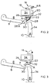
- Figures 2 to 5 are schematic diagrams of the switching mechanism at different stages of the operating of the unit.
- As can be seen from Figure 1, a hedge clipper shown generally at (2) comprises a housing (4) within which is located the motor (not shown). A primary hand (6) is provided with a trigger switch actuator (8). A secondary, bail handle (10) is provided with an actuating mechanism (not shown). The blades (12) are mounted in known manner in the housing (4) for driving by the motor. A guard (14) is mounted on the housing (4), also in known manner, to protect the operator.
- A safety interlock button (16) is located in the upper portion of the housing (4) and projects from the upper surface of the housing. The operation of the button (16) will be described in more detail below.
- As can be seen from Figure 2, the safety interlock button (16) is generally L-shaped, and is slideably mounted in the housing (4) so that the short portion (18) of the "L" projects. The button (16) is free to slide in a substantially horizontal plane, towards the right (with reference to Figure 2), and is biased by a spring (16A) towards the left, (with reference to Figure 2). The free end (20) of the safety interlock button (16), which extends into the housing (4), terminates in a cam section (22).
- A switch (24) is mounted within the housing (4). A switch contact arm (26) extends from the switch in a downwards, substantially vertical (with reference to Figure 2) direction. A rocker element (28) is pivotally mounted at the lower (free) end of the contact arm (26) for pivoting about the axis A and is spring loaded by a spring (28A) into the position shown in Figure 2. Projections (30, 32) are formed in the side wall of the rocker element (28).
- The bail handle (10) engages a switch actuating member (34).
- The operation of the safety interlock mechanism will now be described with reference to Figures 2 to 5, which shown the mechanism in different stages of the operating cycle.
- In Figure 2, the safety interlock button (16) is in the non-engaged position, and the trigger actuator (8) and bail handle (10) are similarly in the non-engaged positions.
- If pressure is applied to the trigger actuator (8) alone, with the safety interlock button in the non-engaged position, as shown in Figure 2, the trigger actuator (8) travels past the rocker element (28) without engaging the projection (30). There is therefore no actuation of the switch (24).
- In Figure 3, the mechanism is shown in the orientation in which the safety interlock button (16) has been pushed to the right (with reference to Figure 3) against the action of the biasing spring. The cam section (22) of the safety interlock (16) engages the projection (32) on the rocker element (28), and causes the rocker element (28) to pivot about its axis A, against the tension of spring (28A), so that the projection (30) on the element is moved into the path of the trigger actuator (8).
- If pressure is applied to the trigger actuator (8), with the safety interlock (16) in the engaged position, the actuator (8) engages the projection (30) of the rocker element (28), allowing it to be further pivoted about the axis A to the position shown in Figure 4.
- With the switch actuating member (34) of the bail handle (10) in the non-engaged position, as shown in Figure 4, the engagement of the trigger actuator (8) with the projection (30) simply causes the rocker element (28) to pivot about the axis A, without actuating the switch contact arm (26).
- However, if, with the safety interlock (16) in the engaged position as shown in Figure 3, pressure is applied simultaneously to the trigger actuator (8) and switch actuating member (34), then the rocker element (28) is not free to pivot about its axis A, but is instead constrained to move in a substantially vertically upwards direction, with reference to Figures 2 to 5, hence actuating the switch contact arm (26) and operating the switch (24). The motor is thus switched on.
- Once the trigger actuator (8) has engaged the projection (30), the operator is free to release the safety interlock (16). However, if the operator releases either the trigger actuator (8), or the switch actuating member (34) associated with the bail handle (10), the pressure on one or other end of the rocker element (28),and hence on the contact arm (26), is released,and the motor is switched off.
- Similarly, it will be clear from the Figures that pressure on the switch actuating member (34) alone will simply position the free end of the switch actuating member (34) below the projection (32) on the rocker element (28) leaving the rocker element (28) in its rest position and therefore not actuating the switch contact arm (26).
Claims (5)
- A manual tool (2) driven by an electric motor, having a primary handle (16) and a secondary handle (10) arranged at a distance from each other, and having a switch (24) which is situated in the manual tool (2) and can only be switched on by the simultaneous actuation of two contact mechanisms (8, 34), one arranged in each handle, (6, 10) the motor being switched off when grip on either handle (6, 10) is released, characterised in that the tool (2) further comprises an initiating device in the form of a safety interlock mechanism (16) which is adapted to prevent actuation of the switch (24), unless said safety interlock mechanism (16) is actuated prior to actuation of said contact mechanism (8) arranged in said primary handle (16).
- A manual tool according to claim 1 characterised in that said safety interlock mechanism (16) operates by means of a cam system which enables actuation of said secondary contact mechanism (34).
- A manual tool according to claim 1 or claim 2, characterised in that the switch (24) is actuated by a switch contact arm (26), on the free end of which a rocker element (28) is pivotally mounted, and operation of the safety interlock (16) allows the contact mechanism (8) of the primary handle (6) to engage the rocker element (28).
- A manual tool according to any of claims 1 to 3 which is a hedge clipper or chainsaw.
- A manual tool according to any of claims 1 to 4 which is a cordless tool.
Applications Claiming Priority (2)
| Application Number | Priority Date | Filing Date | Title |
|---|---|---|---|
| GB9224660 | 1992-11-25 | ||
| GB929224660A GB9224660D0 (en) | 1992-11-25 | 1992-11-25 | Improved switch mechanism |
Publications (2)
| Publication Number | Publication Date |
|---|---|
| EP0599550A1 true EP0599550A1 (en) | 1994-06-01 |
| EP0599550B1 EP0599550B1 (en) | 1997-02-19 |
Family
ID=10725641
Family Applications (1)
| Application Number | Title | Priority Date | Filing Date |
|---|---|---|---|
| EP93309215A Expired - Lifetime EP0599550B1 (en) | 1992-11-25 | 1993-11-18 | Improved switch mechanism |
Country Status (5)
| Country | Link |
|---|---|
| US (1) | US5724737A (en) |
| EP (1) | EP0599550B1 (en) |
| CA (1) | CA2109686A1 (en) |
| DE (1) | DE69308190T2 (en) |
| GB (1) | GB9224660D0 (en) |
Cited By (7)
| Publication number | Priority date | Publication date | Assignee | Title |
|---|---|---|---|---|
| DE19634552A1 (en) * | 1996-08-27 | 1998-03-05 | Metabowerke Kg | Hedge trimmer |
| EP1844646A2 (en) | 2006-04-10 | 2007-10-17 | Andreas Stihl AG & Co. KG | Hedge shears |
| CN102658539A (en) * | 2010-11-22 | 2012-09-12 | 罗伯特·博世有限公司 | Machine tool safety switching device |
| EP2622953A1 (en) * | 2011-12-02 | 2013-08-07 | Makita Corporation | Electric cultivators |
| EP3372348A1 (en) * | 2017-03-11 | 2018-09-12 | Andreas Stihl AG & Co. KG | Manually operated work device |
| WO2018166904A1 (en) * | 2017-03-16 | 2018-09-20 | Robert Bosch Gmbh | Chainsaw |
| US11794371B1 (en) * | 2023-03-29 | 2023-10-24 | Jinyun Mailin Tools Co., Ltd | Hand-held electric chainsaw |
Families Citing this family (40)
| Publication number | Priority date | Publication date | Assignee | Title |
|---|---|---|---|---|
| EP0890302A1 (en) * | 1997-07-11 | 1999-01-13 | Scintilla Ag | Hedge trimmer |
| US6469269B1 (en) * | 2001-04-02 | 2002-10-22 | Jenn Feng Industrial Co., Ltd. | Two-stage self-locking switch structure for hand tools |
| AU780130B2 (en) * | 2001-11-12 | 2005-03-03 | Husqvarna Ab | Safety switch for power tools |
| US6698566B2 (en) * | 2001-11-14 | 2004-03-02 | Jenn Feng Industrial Co., Ltd. | Clutch type safety switch for power tools |
| US6575285B2 (en) * | 2001-11-14 | 2003-06-10 | Jenn Feng Industrial Co., Ltd. | Safety switch for power tools |
| US6548776B1 (en) * | 2002-04-12 | 2003-04-15 | Jenn Feng Industrial Co., Ltd. | Safety device for on/off switch of an electric tool |
| US7143835B2 (en) * | 2003-03-17 | 2006-12-05 | Honda Motor Co., Ltd. | Walk-behind electric working machine |
| GB2404613A (en) * | 2003-07-14 | 2005-02-09 | David Jarman | A vegetation pruning device |
| DE602004001103T2 (en) * | 2003-08-04 | 2007-01-04 | Black & Decker Inc., Newark | Locking mechanism for a pivotable handle assembly of a power tool |
| GB2404550A (en) * | 2003-08-04 | 2005-02-09 | Black & Decker Inc | Latch mechanism for pivoting handle assembly of a power tool |
| GB2404832A (en) * | 2003-08-09 | 2005-02-16 | Black & Decker Inc | Safety mechanism for power tool |
| US6878888B1 (en) | 2004-03-24 | 2005-04-12 | Jenn Peng Industrial Co., Ltd. | Safety device for activating electric tools |
| US20050210685A1 (en) * | 2004-03-24 | 2005-09-29 | Jung-Chang Jong | Brake mechanism for tool |
| US7040559B2 (en) | 2004-04-02 | 2006-05-09 | Fellowes Inc. | Shredder with lock for on/off switch |
| US6909061B1 (en) | 2004-04-07 | 2005-06-21 | Jenn Feng Industrial Co., Ltd | Trigger-brake structure for tool machine |
| ATE378152T1 (en) * | 2004-09-22 | 2007-11-15 | Black & Decker Inc | LOCKING PUSH BUTTON FOR A HAMMER DRILL |
| US8008812B2 (en) | 2006-07-14 | 2011-08-30 | Aurora Office Equipment Co., Ltd. | Paper shredder control system responsive to touch-sensitive element |
| CN2915259Y (en) | 2006-07-14 | 2007-06-27 | 上海震旦办公设备有限公司 | Paper shredder touch safety device |
| US20080053994A1 (en) * | 2006-08-30 | 2008-03-06 | Aurora Office Equipment Co., Ltd. Shanghai | Paper-Breaker Wastebin Structure |
| JP4983663B2 (en) * | 2008-03-17 | 2012-07-25 | 富士重工業株式会社 | Brush cutter operation handle and brush cutter |
| CN201239643Y (en) | 2008-08-06 | 2009-05-20 | 上海震旦办公设备有限公司 | Full automatic paper crusher without selecting paper |
| CN201244502Y (en) | 2008-08-19 | 2009-05-27 | 上海震旦办公设备有限公司 | Structure capable of removing nail of automatic paper crusher |
| US8833485B2 (en) * | 2009-04-08 | 2014-09-16 | Husqvarna Ab | Battery-powered portable tools |
| WO2010115438A1 (en) * | 2009-04-08 | 2010-10-14 | Husqvarna Ab | Battery-powered portable tools |
| CN101543799B (en) * | 2009-04-28 | 2012-10-10 | 上海震旦办公设备有限公司 | Novel protector for paper crusher |
| CN101543800A (en) * | 2009-05-07 | 2009-09-30 | 上海震旦办公设备有限公司 | Paper jamming prevention protective device of paper shredder |
| DE102010054724A1 (en) * | 2010-12-16 | 2012-06-21 | Knorr-Bremse Systeme für Schienenfahrzeuge GmbH | Mechanical actuator |
| US8723468B2 (en) | 2011-04-28 | 2014-05-13 | Aurora Office Equipment Co., Ltd. | Cooled motor |
| US8708260B2 (en) | 2011-08-08 | 2014-04-29 | Aurora Office Equipment Co., Ltd. | Depowered standby paper shredder and method |
| WO2014071838A1 (en) * | 2012-11-08 | 2014-05-15 | 苏州宝时得电动工具有限公司 | Pruning shears |
| CN103843597B (en) * | 2012-12-05 | 2016-09-14 | 苏州宝时得电动工具有限公司 | Shrub and hedge trimmer |
| CN103891533B (en) * | 2012-12-28 | 2016-02-17 | 苏州宝时得电动工具有限公司 | Shrub and hedge trimmer |
| CN103891534B (en) * | 2012-12-28 | 2015-08-19 | 苏州宝时得电动工具有限公司 | A kind of pruning tool |
| US10442107B2 (en) * | 2013-11-12 | 2019-10-15 | Sawstop Holding Llc | Control systems for power tools |
| CN203769947U (en) * | 2013-12-31 | 2014-08-13 | 青岛骏力丰机电有限公司 | Accelerator safety control device of small gasoline digging machine |
| US9701006B2 (en) | 2014-02-20 | 2017-07-11 | Ingersoll-Rand Company | Power tools with reconfigurable secondary switch |
| US9675011B2 (en) * | 2014-10-28 | 2017-06-13 | Black & Decker Inc. | Shearing tool |
| DE102016003426A1 (en) * | 2016-03-21 | 2017-09-21 | Andreas Stihl Ag & Co. Kg | Hand-held implement with a device for commissioning an electric drive motor |
| EP3593951A1 (en) * | 2018-07-11 | 2020-01-15 | Hilti Aktiengesellschaft | Handheld machine tool |
| EP3959039B1 (en) * | 2019-04-26 | 2023-02-22 | Atlas Copco Industrial Technique AB | Hand held power tool |
Citations (3)
| Publication number | Priority date | Publication date | Assignee | Title |
|---|---|---|---|---|
| GB1057790A (en) * | 1965-10-28 | 1967-02-08 | Lear Siegler Inc | Machinery safety device |
| DE3023033A1 (en) * | 1980-06-20 | 1982-01-14 | Metabowerke GmbH & Co, 7440 Nürtingen | Electrical hedge trimmer or chain saw - with safety motor switch using two spaced operating elements requiring simultaneous operation |
| FR2613270A1 (en) * | 1987-04-03 | 1988-10-07 | Inst Nat Rech Securite | Safety control device for portable electrical appliance and appliance equipped with this device |
Family Cites Families (11)
| Publication number | Priority date | Publication date | Assignee | Title |
|---|---|---|---|---|
| US2182018A (en) * | 1937-04-02 | 1939-12-05 | Harris Seybold Potter Co | Two-hand control |
| US4207675A (en) * | 1978-05-15 | 1980-06-17 | Clarence Burchell | Adjustable utility extension handle for electrically powered handtool |
| IT7922984V0 (en) * | 1979-10-29 | 1979-10-29 | Star Utensili Elett | PORTABLE ELECTRIC TOOL WITH PERFECTED CONTROLS. |
| DE3006405A1 (en) * | 1980-02-21 | 1981-08-27 | Gardena Kress + Kastner Gmbh, 7900 Ulm | Hand held power tool with two operating pushbuttons - which cooperate and move shared rod that actuates shared switch, when both buttons are depressed |
| GB2139329B (en) * | 1983-03-04 | 1986-09-10 | Black & Decker Inc | Improvements in or relating to hand-controlled electrically-powered appliances |
| FR2558567B1 (en) * | 1984-01-23 | 1986-08-29 | Peugeot Outillage Elect | DEVICE FOR DUAL MECHANICAL CONTROL OF A SWITCH, AND MACHINE COMPRISING THE SAME |
| US4569431A (en) * | 1984-05-17 | 1986-02-11 | Terryl K. Qualey | Dual hand control |
| US4900881A (en) * | 1988-10-24 | 1990-02-13 | Breuer Electric Mfg. Co. | Safety interlock for floor maintenance machine and method |
| DE3929441C2 (en) * | 1989-09-05 | 1998-09-10 | Stihl Maschf Andreas | Hand-held implement |
| US5150523A (en) * | 1991-07-11 | 1992-09-29 | Ryobi Motor Products Corporation | Deadman switch arrangement for a hedge trimmer |
| US5369236A (en) * | 1992-10-01 | 1994-11-29 | Black & Decker Inc. | Control switch arrangement for orbital polisher |
-
1992
- 1992-11-25 GB GB929224660A patent/GB9224660D0/en active Pending
-
1993
- 1993-11-18 DE DE69308190T patent/DE69308190T2/en not_active Expired - Lifetime
- 1993-11-18 EP EP93309215A patent/EP0599550B1/en not_active Expired - Lifetime
- 1993-11-22 CA CA002109686A patent/CA2109686A1/en not_active Abandoned
-
1995
- 1995-11-01 US US08/551,390 patent/US5724737A/en not_active Expired - Lifetime
Patent Citations (3)
| Publication number | Priority date | Publication date | Assignee | Title |
|---|---|---|---|---|
| GB1057790A (en) * | 1965-10-28 | 1967-02-08 | Lear Siegler Inc | Machinery safety device |
| DE3023033A1 (en) * | 1980-06-20 | 1982-01-14 | Metabowerke GmbH & Co, 7440 Nürtingen | Electrical hedge trimmer or chain saw - with safety motor switch using two spaced operating elements requiring simultaneous operation |
| FR2613270A1 (en) * | 1987-04-03 | 1988-10-07 | Inst Nat Rech Securite | Safety control device for portable electrical appliance and appliance equipped with this device |
Cited By (12)
| Publication number | Priority date | Publication date | Assignee | Title |
|---|---|---|---|---|
| DE19634552A1 (en) * | 1996-08-27 | 1998-03-05 | Metabowerke Kg | Hedge trimmer |
| EP1844646A2 (en) | 2006-04-10 | 2007-10-17 | Andreas Stihl AG & Co. KG | Hedge shears |
| US7958642B2 (en) | 2006-04-10 | 2011-06-14 | Andreas Stihl Ag & Co. Kg | Hedge trimmer |
| US9572302B2 (en) | 2006-04-10 | 2017-02-21 | Andreas Stihl Ag & Co. Kg | Outdoor power tool |
| US9943039B2 (en) | 2006-04-10 | 2018-04-17 | Andreas Stihl Ag & Co Kg | Outdoor power tool |
| CN102658539A (en) * | 2010-11-22 | 2012-09-12 | 罗伯特·博世有限公司 | Machine tool safety switching device |
| CN102658539B (en) * | 2010-11-22 | 2016-03-23 | 罗伯特·博世有限公司 | Toolroom machine safety switching apparatus |
| EP2622953A1 (en) * | 2011-12-02 | 2013-08-07 | Makita Corporation | Electric cultivators |
| EP3372348A1 (en) * | 2017-03-11 | 2018-09-12 | Andreas Stihl AG & Co. KG | Manually operated work device |
| US11772221B2 (en) | 2017-03-11 | 2023-10-03 | Andreas Stihl Ag & Co. Kg | Handheld work apparatus |
| WO2018166904A1 (en) * | 2017-03-16 | 2018-09-20 | Robert Bosch Gmbh | Chainsaw |
| US11794371B1 (en) * | 2023-03-29 | 2023-10-24 | Jinyun Mailin Tools Co., Ltd | Hand-held electric chainsaw |
Also Published As
| Publication number | Publication date |
|---|---|
| CA2109686A1 (en) | 1994-05-26 |
| EP0599550B1 (en) | 1997-02-19 |
| DE69308190D1 (en) | 1997-03-27 |
| US5724737A (en) | 1998-03-10 |
| DE69308190T2 (en) | 1997-06-05 |
| GB9224660D0 (en) | 1993-01-13 |
Similar Documents
| Publication | Publication Date | Title |
|---|---|---|
| EP0599550B1 (en) | Improved switch mechanism | |
| US5969312A (en) | Ambidextrous powers-switch lock-out mechanism | |
| US4432139A (en) | Safety device on a power saw | |
| US5005295A (en) | Portable power driven tool | |
| US9636792B2 (en) | Handheld work apparatus having a drive motor for driving a work tool and method for operating said apparatus | |
| US10594116B2 (en) | Tool having an inclined handle | |
| US5685080A (en) | Battery powered chain saw | |
| US5150523A (en) | Deadman switch arrangement for a hedge trimmer | |
| EP1808274B1 (en) | Power Tool | |
| US4044532A (en) | Two-motion switch for cordless lawnmower | |
| US3971906A (en) | Trigger-lock control | |
| CN106514568B (en) | Method for starting a hand-guided work apparatus having an electric motor | |
| EP0469757B1 (en) | Power tool | |
| EP1387376B1 (en) | Switch lock-off mechanism for power tools | |
| US4531347A (en) | Lawn mower with wheel drive | |
| JP3630966B2 (en) | Portable power tool | |
| CN110125882B (en) | Switch device for electrically driven garden tool | |
| GB2426805A (en) | Handheld tool which cannot be switched on if the safety brakes are not functional or are worn | |
| US20050102839A1 (en) | Latch mechanism for pivoting handle assembly of a power tool | |
| EP2783796A1 (en) | Safety device for actuating a nailer | |
| EP1787507A2 (en) | Power tool | |
| CN117773225A (en) | Cutting tool | |
| CA1110298A (en) | Actuator mechanism for a portable hand-held tool | |
| GB2220104A (en) | Switchbox |
Legal Events
| Date | Code | Title | Description |
|---|---|---|---|
| PUAI | Public reference made under article 153(3) epc to a published international application that has entered the european phase |
Free format text: ORIGINAL CODE: 0009012 |
|
| AK | Designated contracting states |
Kind code of ref document: A1 Designated state(s): DE FR GB IT SE |
|
| 17P | Request for examination filed |
Effective date: 19941103 |
|
| GRAG | Despatch of communication of intention to grant |
Free format text: ORIGINAL CODE: EPIDOS AGRA |
|
| 17Q | First examination report despatched |
Effective date: 19960429 |
|
| GRAH | Despatch of communication of intention to grant a patent |
Free format text: ORIGINAL CODE: EPIDOS IGRA |
|
| GRAH | Despatch of communication of intention to grant a patent |
Free format text: ORIGINAL CODE: EPIDOS IGRA |
|
| GRAA | (expected) grant |
Free format text: ORIGINAL CODE: 0009210 |
|
| AK | Designated contracting states |
Kind code of ref document: B1 Designated state(s): DE FR GB IT SE |
|
| PG25 | Lapsed in a contracting state [announced via postgrant information from national office to epo] |
Ref country code: IT Free format text: LAPSE BECAUSE OF FAILURE TO SUBMIT A TRANSLATION OF THE DESCRIPTION OR TO PAY THE FEE WITHIN THE PRESCRIBED TIME-LIMIT;WARNING: LAPSES OF ITALIAN PATENTS WITH EFFECTIVE DATE BEFORE 2007 MAY HAVE OCCURRED AT ANY TIME BEFORE 2007. THE CORRECT EFFECTIVE DATE MAY BE DIFFERENT FROM THE ONE RECORDED. Effective date: 19970219 |
|
| REF | Corresponds to: |
Ref document number: 69308190 Country of ref document: DE Date of ref document: 19970327 |
|
| ET | Fr: translation filed | ||
| PG25 | Lapsed in a contracting state [announced via postgrant information from national office to epo] |
Ref country code: SE Effective date: 19970519 |
|
| PLBE | No opposition filed within time limit |
Free format text: ORIGINAL CODE: 0009261 |
|
| STAA | Information on the status of an ep patent application or granted ep patent |
Free format text: STATUS: NO OPPOSITION FILED WITHIN TIME LIMIT |
|
| 26N | No opposition filed | ||
| REG | Reference to a national code |
Ref country code: GB Ref legal event code: IF02 |
|
| PGFP | Annual fee paid to national office [announced via postgrant information from national office to epo] |
Ref country code: DE Payment date: 20101126 Year of fee payment: 18 |
|
| PGFP | Annual fee paid to national office [announced via postgrant information from national office to epo] |
Ref country code: GB Payment date: 20101124 Year of fee payment: 18 |
|
| PGFP | Annual fee paid to national office [announced via postgrant information from national office to epo] |
Ref country code: FR Payment date: 20111128 Year of fee payment: 19 |
|
| GBPC | Gb: european patent ceased through non-payment of renewal fee |
Effective date: 20121118 |
|
| REG | Reference to a national code |
Ref country code: FR Ref legal event code: ST Effective date: 20130731 |
|
| REG | Reference to a national code |
Ref country code: DE Ref legal event code: R119 Ref document number: 69308190 Country of ref document: DE Effective date: 20130601 |
|
| PG25 | Lapsed in a contracting state [announced via postgrant information from national office to epo] |
Ref country code: DE Free format text: LAPSE BECAUSE OF NON-PAYMENT OF DUE FEES Effective date: 20130601 |
|
| PG25 | Lapsed in a contracting state [announced via postgrant information from national office to epo] |
Ref country code: GB Free format text: LAPSE BECAUSE OF NON-PAYMENT OF DUE FEES Effective date: 20121118 Ref country code: FR Free format text: LAPSE BECAUSE OF NON-PAYMENT OF DUE FEES Effective date: 20121130 |