EP0599529A2 - Verfahren und Gerät zur Bildkodierung und Verfahren und Gerät zur Bilddekodierung - Google Patents
Verfahren und Gerät zur Bildkodierung und Verfahren und Gerät zur Bilddekodierung Download PDFInfo
- Publication number
- EP0599529A2 EP0599529A2 EP19930309121 EP93309121A EP0599529A2 EP 0599529 A2 EP0599529 A2 EP 0599529A2 EP 19930309121 EP19930309121 EP 19930309121 EP 93309121 A EP93309121 A EP 93309121A EP 0599529 A2 EP0599529 A2 EP 0599529A2
- Authority
- EP
- European Patent Office
- Prior art keywords
- coding
- frame
- picture
- field
- unit
- Prior art date
- Legal status (The legal status is an assumption and is not a legal conclusion. Google has not performed a legal analysis and makes no representation as to the accuracy of the status listed.)
- Granted
Links
Images


Classifications
-
- H—ELECTRICITY
- H04—ELECTRIC COMMUNICATION TECHNIQUE
- H04N—PICTORIAL COMMUNICATION, e.g. TELEVISION
- H04N19/00—Methods or arrangements for coding, decoding, compressing or decompressing digital video signals
- H04N19/85—Methods or arrangements for coding, decoding, compressing or decompressing digital video signals using pre-processing or post-processing specially adapted for video compression
-
- H—ELECTRICITY
- H04—ELECTRIC COMMUNICATION TECHNIQUE
- H04N—PICTORIAL COMMUNICATION, e.g. TELEVISION
- H04N19/00—Methods or arrangements for coding, decoding, compressing or decompressing digital video signals
- H04N19/10—Methods or arrangements for coding, decoding, compressing or decompressing digital video signals using adaptive coding
- H04N19/102—Methods or arrangements for coding, decoding, compressing or decompressing digital video signals using adaptive coding characterised by the element, parameter or selection affected or controlled by the adaptive coding
- H04N19/103—Selection of coding mode or of prediction mode
- H04N19/105—Selection of the reference unit for prediction within a chosen coding or prediction mode, e.g. adaptive choice of position and number of pixels used for prediction
-
- H—ELECTRICITY
- H04—ELECTRIC COMMUNICATION TECHNIQUE
- H04N—PICTORIAL COMMUNICATION, e.g. TELEVISION
- H04N19/00—Methods or arrangements for coding, decoding, compressing or decompressing digital video signals
- H04N19/10—Methods or arrangements for coding, decoding, compressing or decompressing digital video signals using adaptive coding
- H04N19/102—Methods or arrangements for coding, decoding, compressing or decompressing digital video signals using adaptive coding characterised by the element, parameter or selection affected or controlled by the adaptive coding
- H04N19/103—Selection of coding mode or of prediction mode
- H04N19/112—Selection of coding mode or of prediction mode according to a given display mode, e.g. for interlaced or progressive display mode
-
- H—ELECTRICITY
- H04—ELECTRIC COMMUNICATION TECHNIQUE
- H04N—PICTORIAL COMMUNICATION, e.g. TELEVISION
- H04N19/00—Methods or arrangements for coding, decoding, compressing or decompressing digital video signals
- H04N19/10—Methods or arrangements for coding, decoding, compressing or decompressing digital video signals using adaptive coding
- H04N19/134—Methods or arrangements for coding, decoding, compressing or decompressing digital video signals using adaptive coding characterised by the element, parameter or criterion affecting or controlling the adaptive coding
- H04N19/136—Incoming video signal characteristics or properties
- H04N19/137—Motion inside a coding unit, e.g. average field, frame or block difference
-
- H—ELECTRICITY
- H04—ELECTRIC COMMUNICATION TECHNIQUE
- H04N—PICTORIAL COMMUNICATION, e.g. TELEVISION
- H04N19/00—Methods or arrangements for coding, decoding, compressing or decompressing digital video signals
- H04N19/10—Methods or arrangements for coding, decoding, compressing or decompressing digital video signals using adaptive coding
- H04N19/134—Methods or arrangements for coding, decoding, compressing or decompressing digital video signals using adaptive coding characterised by the element, parameter or criterion affecting or controlling the adaptive coding
- H04N19/136—Incoming video signal characteristics or properties
- H04N19/14—Coding unit complexity, e.g. amount of activity or edge presence estimation
-
- H—ELECTRICITY
- H04—ELECTRIC COMMUNICATION TECHNIQUE
- H04N—PICTORIAL COMMUNICATION, e.g. TELEVISION
- H04N19/00—Methods or arrangements for coding, decoding, compressing or decompressing digital video signals
- H04N19/60—Methods or arrangements for coding, decoding, compressing or decompressing digital video signals using transform coding
- H04N19/61—Methods or arrangements for coding, decoding, compressing or decompressing digital video signals using transform coding in combination with predictive coding
-
- H—ELECTRICITY
- H04—ELECTRIC COMMUNICATION TECHNIQUE
- H04N—PICTORIAL COMMUNICATION, e.g. TELEVISION
- H04N19/00—Methods or arrangements for coding, decoding, compressing or decompressing digital video signals
- H04N19/30—Methods or arrangements for coding, decoding, compressing or decompressing digital video signals using hierarchical techniques, e.g. scalability
Definitions
- the invention relates to method and apparatus for picture coding and method and apparatus for picture decoding, and more particularly to method and apparatus for picture coding and method and apparatus for picture decoding of high efficiency effective for transmission or recording of digital images.
- the transfer rate of digital image reaches hundreds of Mbps to several Gbps, and processing of digital image is restricted by the communication cost at the time of transmission, and limited by the recording capacity of the recording apparatus at the time of recording. It has been accordingly attempted to develop method and apparatus for picture coding capable of minimizing the deterioration of picture quality and lowering the transfer rate at the same time.
- the motion compensation interframe differential two-dimensional discrete cosine transform (DCT) of the CCIR H.261 standard is described below.
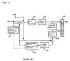
- Fig. 8 is a block diagram of motion compensation interframe differential two-dimensional DCT.
- numeral 101 denotes a DCT circuit
- 102 is a quantizer
- 103 is an inverse quantizer
- 104 is an inverse DCT circuit
- 105 is a frame memory
- 106 is an interframe motion compensation circuit
- 107 is an interframe motion detection circuit
- 108 is an intraframe/interframe changeover circuit
- 109 is a variable length coding circuit.
- the input is an interlaced image called common intermediate format (CIF).
- Fig. 9 is a time-space configuration of pixels of input picture, in which the axis of abscissas denotes the time direction and the axis of ordinates represents the vertical direction or the line direction.
- a set of pixels equal in the time axis is called a CIF frame, and coding is performed in the unit of CIF frame.
- the first frame of coding that is, the picture of frame t is changed over to intraframe coding by an intraframe/interframe changeover signal 108, and is subjected to intraframe coding without considering the difference. That is, the image data is converted into a transform coefficient in the DCT circuit 101 in the unit of two-dimensional block, and the transform coefficient is quantized in the quantizer 102, and is subjected to variable length coding in the variable length coding circuit 109, and is sent out into a transmission route.
- the picture is high in correlation, and, as a result of DCT, the energy is concentrated in the transform coefficient corresponding to the low frequency components.
- the transform coefficient after quantizing is simultaneously returned to the real time data via the inverse quantizer 103 and inverse DCT circuit 104, and accumulated in the frame memory 105.
- the pictures after frame (t+1) are subjected to interframe differential coding in each frame.
- the interframe motion vector is determined in every two-dimensional block.
- the interframe motion compensation circuit 106 generates, making use of the detected motion vector, a predicted value compensating the motion of the next frame in the unit of two-dimensional block.
- the picture of frame (t+1) is compared with the predicted value generated from frame t in the above method, and the difference or prediction error is calculated. Afterwards, the prediction error is coded in the same manner as in frame t. After frame (t+2), the prediction error is coded in the same manner as in the method of frame (t+1).
- Fig. 10 is a time-space configuration of pixels of interlaced picture.
- Figs. 11 and 12 explain examples of display of interlaced picture in frame, without motion in Fig. 11, and with a horizontal motion in Fig. 12.
- Pixels are disposed at positions deviated in time in every one vertical line by interlacing.
- a set of pixels equal in the time axis is called a field, and two fields differing in the time axis are put together to form a frame, and one frame is composed of field 1 and field 2.
- the frame picture is an image of high vertical correlation. With motion involved, the frame picture is deviated by the amount of interfield motion in every field, that is, in every line as shown in Fig. 12.
- one of the preferred embodiments of the invention comprises: means for receiving and storing picture data composed in frames, activity calculating means for calculating the activity of the picture data in every frame, frame/field coding judging means for receiving the activity, and judging to perform frame unit coding when the activity is over a specific value or to perform field unit coding by dividing a frame into fields when the activity is below a specific value, and coding means for coding in frame unit or coding in field unit concerning the picture data on the basis of the judgement, and issuing a coded picture signal containing the frame/field coding judgement signal, whereby picture coding of high efficiency is realized despite magnitude of motion, by coding in field unit when the motion of picture is large, and coding in frame unit by making use of the vertical correlation of picture when the motion is small.
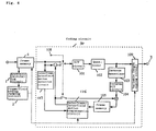
- Fig. 1 is a block diagram of a first embodiment of a picture coding apparatus according to the invention.
- Fig. 2 is an explanatory diagram of coding in frame unit and coding in field unit of the invention.
- Fig. 3 is a block diagram of activity calculating circuit 1 and frame/field coding judging circuit 2 in Fig. 1.
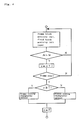
- Fig. 4 is a flow chart showing processing in frame/field coding judging circuit of the invention.
- Fig. 5 is a flow chart showing processing in frame/field coding judging circuit in a second embodiment of the invention.
- Fig. 6 is a block diagram of a third embodiment of picture coding apparatus according to the invention.
- Fig. 7 is a block diagram of an embodiment of a picture decoding apparatus according to the invention.
- Fig. 8 is a block diagram of a conventional motion compensation interframe differential two-dimensional DCT.
- Fig. 9 is a time-space configuration diagram of pixels of CIF.
- Fig. 10 is a time-space configuration diagram of pixels of interlaced picture.
- Fig. 11 is an explanatory diagram of frame picture without motion.
- Fig. 12 is an explanatory diagram of frame picture with motion.
- Fig. 1 is a block diagram of a picture coding apparatus according to the first embodiment of the invention
- Fig. 2 is an explanatory diagram of coding in frame unit and coding in field unit
- Fig. 3 is a block diagram of activity calculating circuit and frame/field coding judging circuit in Fig. 1
- Fig. 4 is a flow chart showing processing in frame/field coding judging circuit 2.
- numeral 1 denotes an activity calculating circuit
- 2 is a frame/field coding judging circuit
- 3 is a coding circuit
- 4 is a frame memory
- 5 is a coded picture output terminal.
- Fig. 1 The image coding apparatus in Fig. 1 is explained by reference to Figs. 1, 2, 3 and 4.
- the input picture in frame unit is stored in the frame memory 4, and at the same time the frame block activity Ar and field block activity Ai are calculated in the activity calculating circuit 1.
- This activity is calculated, for example, as follows.
- the input picture is divided into two-dimensional small blocks, and sequentially numbered in the frame unit as shown in Fig. 2 (a), as frame small block Sbr (x,y) (x: horizontal pixel address, 1 ⁇ x ⁇ 8, y: vertical pixel address, 1 ⁇ y ⁇ 8), and sequentially numbered in the frame unit as shown in Fig. 2 (b), as picture data of field small block Sbi (x,y,n) (x: horizontal pixel address, 1 ⁇ x ⁇ 8, y: vertical pixel address, 1 ⁇ y ⁇ 4, n: small block address 1 ⁇ n ⁇ 2). Consequently, adding the energy sum of interline difference of every line in each block, the frame and field block activities are obtained. They are expressed in the following equations.
- Fig. 3 is an example of activity calculating circuit 1, which comprises a buffer memory 11 for dividing the input picture into two-dimensional small blocks, an address generating circuit 12 for generating its address, first and second square error calculating circuits 13, 14 for calculating square errors or Ar, Ai, and a multiplexer 15 for multiplexing and issuing Ar, Ai.
- the frame/field coding judging circuit 2 is composed of central processing unit (CPU).
- CPU central processing unit
- Fig. 4 which shows the operation of the CPU.
- the input frame activity Ar and field activity Ai are compared in magnitude in every two-dimensional block, and the number ⁇ of blocks of Ai>Ar in one frame is calculated.
- ⁇ is compared with an experimentally determined value T1, and if ⁇ ⁇ T1, a change-over signal showing frame coding is issued, and if ⁇ ⁇ T1, a changeover signal showing field coding is issued, in every frame.
- coding in frame unit and field unit is coding or decoding in the unit of frame in terms of the time, or in the unit of field, as shown in Fig.
- field 1 and field 2 of time t must be coded and decoded simultaneously, but in the field unit, on the other hand, field 1 and field 2 of time t are coded and decoded at separate times.
- the coding circuit 3 employs, for example, a motion compensation interframe differential two-dimensional DCT circuit in the prior art, and a motion compensation interfield differential two-dimensional DCT circuit applying the prior art in the field unit.
- the main difference between the motion compensation interframe differential two-dimensional DCT circuit and the motion compensation interfield differential two-dimensional DCT circuit are whether the object of coding is the block in frame unit as shown in Fig. 2 (a) or the block in field unit as shown in Fig. 2 (b), and whether the motion detection and motion compensation are frame interval or field interval. Therefore, the difference in circuit lies only in the motion detection circuits 107, 117, and motion compensation circuits 106, 116.
- the frame memory 4 issues a frame block.
- the frame unit block is fed into the motion compensation interframe differential two-dimensional DCT circuit, and at the same time, the input of the variable length coding circuit 109 is changed over to the quantizer 102 in the motion compensation interframe differential two-dimensional DCT circuit.
- the block in the field unit is coded.
- the result of judgement by the frame/field coding judging circuit 2 is sent out from the output terminal 5, together with the coded picture signal, through the variable length coding circuit 109.
- Fig. 5 is a flow chart showing processing in the CPU of the frame/field coding judging circuit 2 in a second embodiment of the invention. What differs from the first embodiment is that the frame coding and field coding are not changed over in every frame, but only once in every N frames.
- the pointer ⁇ showing how many frames have satisfied ⁇ ⁇ T1 is added.
- intraframe coding is inserted in a specific period.
- the period of intraframe coding is regarded as N frames, and the coding in frame unit and coding in field unit are changed over in the intraframe coding period N. Accordingly, changeover of coding occurs only in N frame periods, and the load of the hardware can be alleviated.
- coding in frame unit and in field unit is frequency changed over in every frame, the picture quality may fluctuate, but it is changed over in every N frames in the second embodiment, so that fluctuation of picture quality may be avoided.
- the block activities Ar, Ai are determined by the difference between the lines, but it is not limitative, and for example, it may be the sum of the AC energy of frame and field blocks. That is, using Sbr, Sbi in the first embodiment, first the mean values of each small block mr, mi(n) are determined. Then, using mean values mr, mi(n), the AC energy of each small block is determined, and the sum of AC energies of small blocks is calculated to obtain Ar, Ai. They are expressed in the following equations.
- Judgement of coding in frame unit and coding in field unit is done on the basis of the total number of blocks conforming to the conditions by comparing Ai and Ar in each block, but it is not limitative, and the entire picture may be regarded as one block, and comparison of Ai>Ar is determined only once in every frame, and it is judged on the basis of the result, so that same effects may be obtained.
- the initial value of coding may be either frame unit coding or field unit coding, but in general picture, small movements are in majority, and it may be set at frame unit coding.
- Fig. 6 is a block diagram of a third embodiment of a picture coding apparatus of the invention. What differs from the second embodiment is the constitution of the coding circuit. (In Fig. 6, the coding circuit is indicated by numeral 30.) In the second embodiment, the motion compensation interframe differential two-dimensional DCT circuit and motion compensation interfield differential two-dimensional DCT circuit are changed over by the output of the coding judging circuit 2, but in the third embodiment, the output of the coding judging circuit 2 is fed into an interframe/interfield prediction circuit 126, and it is designed so as to be capable of changing over the motion compensation not only in the block unit but also in the entire picture, so that the coding circuit may be composed of the smaller hardware than in the second embodiment.
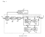
- Fig. 7 is a block diagram of an embodiment of picture decoding apparatus of the invention.
- the apparatus in Fig. 7 comprises a frame/field decoding changeover circuit 6, a decoding circuit 7, a coding image input terminal 8, and a picture output terminal 9, and operates as follows.
- the coded picture input is fed into a variable length decoding circuit 139 inside the decoding circuit 7, and is separated into the picture data and frame/field coding judging signal.
- the frame/field decoding changeover circuit 6 receives the frame/field coding judging signal determined by the activity from the variable length decoding circuit 139, and sends the frame/field decoding changeover signal to the decoding circuit 7.
- the decoding circuit 7 processes the picture data by inverse quantizing and inverse DCT, and compensates the motion in frame unit or field unit depending on the changeover signal in each circuit, reproduces the picture, and issues the decoded picture in frame unit or field unit selected by the changeover signal. Therefore, by the picture decoding apparatus shown in Fig. 7, the picture having being coded by the foregoing embodiments can be decoded.
- the motion compensation prediction circuit is composed of different circuits in every frame or field, but it is also possible to simplify by using the motion compensation interframe/interfield prediction circuit as shown in Fig. 6.
- the motion compensation interframe differential DCT circuit is explained, but it is not limitative, and Hadamard transform, Fourier transform, other orthogonal transform circuits, vector quantizing circuits, and any other means having the function of coding the image can be similarly employed.
Landscapes
- Engineering & Computer Science (AREA)
- Multimedia (AREA)
- Signal Processing (AREA)
- Compression Or Coding Systems Of Tv Signals (AREA)
Applications Claiming Priority (3)
| Application Number | Priority Date | Filing Date | Title |
|---|---|---|---|
| JP314815/92 | 1992-11-25 | ||
| JP31481592 | 1992-11-25 | ||
| JP31481592A JP2684941B2 (ja) | 1992-11-25 | 1992-11-25 | 画像符号化方法及び画像符号化装置 |
Publications (3)
| Publication Number | Publication Date |
|---|---|
| EP0599529A2 true EP0599529A2 (de) | 1994-06-01 |
| EP0599529A3 EP0599529A3 (de) | 1995-09-06 |
| EP0599529B1 EP0599529B1 (de) | 2001-10-10 |
Family
ID=18057940
Family Applications (1)
| Application Number | Title | Priority Date | Filing Date |
|---|---|---|---|
| EP19930309121 Expired - Lifetime EP0599529B1 (de) | 1992-11-25 | 1993-11-15 | Verfahren und Gerät zur Bildkodierung und Verfahren und Gerät zur Bilddekodierung |
Country Status (3)
| Country | Link |
|---|---|
| EP (1) | EP0599529B1 (de) |
| JP (1) | JP2684941B2 (de) |
| DE (1) | DE69330903T2 (de) |
Cited By (8)
| Publication number | Priority date | Publication date | Assignee | Title |
|---|---|---|---|---|
| DE19521973A1 (de) * | 1994-06-15 | 1995-12-21 | Hitachi Ltd | Bilddecodiervorrichtung |
| EP0707426A3 (de) * | 1994-10-11 | 1998-05-20 | Hitachi, Ltd. | Digitaler Videodekoder zum Dekodieren von digitalen hochauflösenden und/oder standardauflösenden Fernsehsignalen |
| GB2370477A (en) * | 2000-12-22 | 2002-06-26 | Tandberg Television Asa | Encoding a multi-dimensional product code |
| EP1659799A1 (de) * | 2004-11-23 | 2006-05-24 | STMicroelectronics Asia Pacific Pte Ltd. | Kantenadaptives Filterungssystem und -verfahren zur Verminderung Blockartefakte |
| GB2454240A (en) * | 2007-11-01 | 2009-05-06 | Tandberg Television Asa | Picture adaptive frame or field (PAFF) coding for MPEG2 using temporal displacement and distortion thresholds |
| US7961786B2 (en) | 2003-09-07 | 2011-06-14 | Microsoft Corporation | Signaling field type information |
| US8107531B2 (en) | 2003-09-07 | 2012-01-31 | Microsoft Corporation | Signaling and repeat padding for skip frames |
| US8116380B2 (en) | 2003-09-07 | 2012-02-14 | Microsoft Corporation | Signaling for field ordering and field/frame display repetition |
Families Citing this family (11)
| Publication number | Priority date | Publication date | Assignee | Title |
|---|---|---|---|---|
| US6973126B1 (en) | 1999-03-05 | 2005-12-06 | Kdd Corporation | Video coding apparatus according to a feature of a video picture |
| FR2857205B1 (fr) * | 2003-07-04 | 2005-09-23 | Nextream France | Dispositif et procede de codage de donnees video |
| US8064520B2 (en) | 2003-09-07 | 2011-11-22 | Microsoft Corporation | Advanced bi-directional predictive coding of interlaced video |
| JP4775132B2 (ja) * | 2006-06-20 | 2011-09-21 | ソニー株式会社 | 画像理装置および方法、プログラム、並びに記録媒体 |
| FR2903271A1 (fr) * | 2006-06-30 | 2008-01-04 | Thomson Licensing Sa | Procede de codage en mode trame ou bitrame |
| JP4561701B2 (ja) * | 2006-07-04 | 2010-10-13 | 日本ビクター株式会社 | 動画像符号化装置 |
| JP2008078977A (ja) * | 2006-09-21 | 2008-04-03 | Victor Co Of Japan Ltd | 画像符号化装置 |
| JP4723541B2 (ja) * | 2007-07-12 | 2011-07-13 | 日本放送協会 | 画像符号化装置 |
| JP4603019B2 (ja) * | 2007-07-12 | 2010-12-22 | 日本放送協会 | 画像符号化装置 |
| US8699778B2 (en) | 2009-07-29 | 2014-04-15 | Panasonic Corporation | Image coding method, image coding apparatus, program, and integrated circuit |
| JP5759269B2 (ja) * | 2011-06-01 | 2015-08-05 | 株式会社日立国際電気 | 映像符号化装置 |
Citations (5)
| Publication number | Priority date | Publication date | Assignee | Title |
|---|---|---|---|---|
| US3761613A (en) * | 1972-06-20 | 1973-09-25 | Bell Telephone Labor Inc | Dual mode video encoder |
| US4217609A (en) * | 1978-02-28 | 1980-08-12 | Kokusai Denshin Denwa Kabushiki Kaisha | Adaptive predictive coding system for television signals |
| JPS58137379A (ja) * | 1982-02-10 | 1983-08-15 | Nec Corp | 動き補償フレ−ム間・フイ−ルド間符号化装置 |
| WO1987004033A1 (en) * | 1985-12-24 | 1987-07-02 | British Broadcasting Corporation | Method of coding a video signal for transmission in a restricted bandwidth |
| EP0510972A2 (de) * | 1991-04-25 | 1992-10-28 | Matsushita Electric Industrial Co., Ltd. | Verfahren und Gerät zur Bildkodierung |
Family Cites Families (2)
| Publication number | Priority date | Publication date | Assignee | Title |
|---|---|---|---|---|
| JP3125145B2 (ja) * | 1990-08-29 | 2001-01-15 | 日立電子株式会社 | 画像データの高能率符号化方法及びその装置 |
| JP3092280B2 (ja) * | 1991-07-30 | 2000-09-25 | ソニー株式会社 | 画像信号の高能率符号化及び復号化装置 |
-
1992
- 1992-11-25 JP JP31481592A patent/JP2684941B2/ja not_active Expired - Lifetime
-
1993
- 1993-11-15 EP EP19930309121 patent/EP0599529B1/de not_active Expired - Lifetime
- 1993-11-15 DE DE1993630903 patent/DE69330903T2/de not_active Expired - Lifetime
Patent Citations (5)
| Publication number | Priority date | Publication date | Assignee | Title |
|---|---|---|---|---|
| US3761613A (en) * | 1972-06-20 | 1973-09-25 | Bell Telephone Labor Inc | Dual mode video encoder |
| US4217609A (en) * | 1978-02-28 | 1980-08-12 | Kokusai Denshin Denwa Kabushiki Kaisha | Adaptive predictive coding system for television signals |
| JPS58137379A (ja) * | 1982-02-10 | 1983-08-15 | Nec Corp | 動き補償フレ−ム間・フイ−ルド間符号化装置 |
| WO1987004033A1 (en) * | 1985-12-24 | 1987-07-02 | British Broadcasting Corporation | Method of coding a video signal for transmission in a restricted bandwidth |
| EP0510972A2 (de) * | 1991-04-25 | 1992-10-28 | Matsushita Electric Industrial Co., Ltd. | Verfahren und Gerät zur Bildkodierung |
Non-Patent Citations (3)
| Title |
|---|
| PATENT ABSTRACTS OF JAPAN vol. 7 no. 251 (E-209) ,8 November 1983 & JP-A-58 137379 (NIPPON DENKI K.K.) 15 August 1983, * |
| SIGNAL PROCESSING IMAGE COMMUNICATION., vol. 2, no. 3, October 1990 AMSTERDAM NL, pages 333-341, IRIE ET AL. 'ADAPTIVE SUB-BAND DCT CODING FOR HDTV SIGNAL TRANSMISSION' * |
| SIGNAL PROCESSING IMAGE COMMUNICATION., vol. 4, no. 4/5, August 1992 AMSTERDAM NL, pages 379-387, OHTSUKA ET AL. 'Development of 135 Mbit/s HDTV codec' * |
Cited By (21)
| Publication number | Priority date | Publication date | Assignee | Title |
|---|---|---|---|---|
| DE19521973C2 (de) * | 1994-06-15 | 1998-01-29 | Hitachi Ltd | Bilddecodiervorrichtung |
| DE19521973A1 (de) * | 1994-06-15 | 1995-12-21 | Hitachi Ltd | Bilddecodiervorrichtung |
| US7173970B2 (en) | 1994-10-11 | 2007-02-06 | Hitachi America Ltd. | Methods and apparatus for decoding and displaying multiple digital images in parallel |
| EP0707426A3 (de) * | 1994-10-11 | 1998-05-20 | Hitachi, Ltd. | Digitaler Videodekoder zum Dekodieren von digitalen hochauflösenden und/oder standardauflösenden Fernsehsignalen |
| US6061402A (en) * | 1994-10-11 | 2000-05-09 | Hitachi America, Ltd. | Methods and apparatus for efficiently decoding bi-directionally coded image data |
| US6167089A (en) * | 1994-10-11 | 2000-12-26 | Hitachi America, Ltd. | Reduced cost methods and apparatus for decoding bi-directionally coded image data |
| US6249547B1 (en) | 1994-10-11 | 2001-06-19 | Hitachi America, Ltd. | Methods and apparatus for decoding high definition and standard definition digital video images using a single decoder apparatus |
| EP1209916A2 (de) * | 1994-10-11 | 2002-05-29 | Hitachi Ltd. | Digitalvideodekodierer für die Dekodierung digitaler Hochauflösungs- und/oder Standardauflösungsfernsehsignale |
| US7295611B2 (en) | 1994-10-11 | 2007-11-13 | Hitachi America, Ltd. | Methods and apparatus for decoding and displaying different resolution video signals |
| US6563876B2 (en) | 1994-10-11 | 2003-05-13 | Hitachi America, Ltd. | Methods and apparatus for decoding and displaying high definition and standard definition digital video images at standard definition resolution |
| EP1209916A3 (de) * | 1994-10-11 | 2003-07-30 | Hitachi Ltd. | Digitalvideodekodierer für die Dekodierung digitaler Hochauflösungs- und/oder Standardauflösungsfernsehsignale |
| GB2370477B (en) * | 2000-12-22 | 2004-03-03 | Tandberg Television Asa | Method and apparatus for encoding a product code |
| GB2370477A (en) * | 2000-12-22 | 2002-06-26 | Tandberg Television Asa | Encoding a multi-dimensional product code |
| US7961786B2 (en) | 2003-09-07 | 2011-06-14 | Microsoft Corporation | Signaling field type information |
| US8107531B2 (en) | 2003-09-07 | 2012-01-31 | Microsoft Corporation | Signaling and repeat padding for skip frames |
| US8116380B2 (en) | 2003-09-07 | 2012-02-14 | Microsoft Corporation | Signaling for field ordering and field/frame display repetition |
| EP1659799A1 (de) * | 2004-11-23 | 2006-05-24 | STMicroelectronics Asia Pacific Pte Ltd. | Kantenadaptives Filterungssystem und -verfahren zur Verminderung Blockartefakte |
| US7620261B2 (en) | 2004-11-23 | 2009-11-17 | Stmicroelectronics Asia Pacific Pte. Ltd. | Edge adaptive filtering system for reducing artifacts and method |
| GB2454240A (en) * | 2007-11-01 | 2009-05-06 | Tandberg Television Asa | Picture adaptive frame or field (PAFF) coding for MPEG2 using temporal displacement and distortion thresholds |
| WO2009056978A2 (en) * | 2007-11-01 | 2009-05-07 | Telefonaktiebolaget L M Ericsson (Publ) | Picture adaptive frame or field (paff) coding for mpeg2 |
| WO2009056978A3 (en) * | 2007-11-01 | 2009-07-09 | Tandberg Television Asa | Picture adaptive frame or field (paff) coding for mpeg2 |
Also Published As
| Publication number | Publication date |
|---|---|
| DE69330903D1 (de) | 2001-11-15 |
| JPH06165146A (ja) | 1994-06-10 |
| JP2684941B2 (ja) | 1997-12-03 |
| EP0599529A3 (de) | 1995-09-06 |
| DE69330903T2 (de) | 2002-04-04 |
| EP0599529B1 (de) | 2001-10-10 |
Similar Documents
| Publication | Publication Date | Title |
|---|---|---|
| US5784107A (en) | Method and apparatus for picture coding and method and apparatus for picture decoding | |
| EP0599529A2 (de) | Verfahren und Gerät zur Bildkodierung und Verfahren und Gerät zur Bilddekodierung | |
| US6584154B1 (en) | Moving-picture coding and decoding method and apparatus with reduced computational cost | |
| US4217609A (en) | Adaptive predictive coding system for television signals | |
| US6151075A (en) | Device and method for converting frame rate | |
| US6658157B1 (en) | Method and apparatus for converting image information | |
| US6037986A (en) | Video preprocessing method and apparatus with selective filtering based on motion detection | |
| US5424779A (en) | Video coding apparatus | |
| US5502491A (en) | Orthogonal transform coding apparatus and decoding apparatus | |
| US5173773A (en) | Moving picture signal progressive coding system | |
| US7092445B2 (en) | Video coder providing implicit coefficient prediction and scan adaptation for image coding and intra coding of video | |
| US5347309A (en) | Image coding method and apparatus | |
| US4837618A (en) | Moving image signal coding system | |
| US4833535A (en) | Image transmission apparatus | |
| EP0562787B1 (de) | Verfahren und Einrichtung zur Bildkodierung | |
| US5434622A (en) | Image signal encoding apparatus using adaptive frame/field format compression | |
| EP0720374A1 (de) | Vorrichtung zur parallelen Dekodierung von digitalen Bildsignalen | |
| US6744924B1 (en) | Error concealment in a video signal | |
| EP0644695A2 (de) | Räumliche skalierbare Bildkodierung und -dekodierung | |
| EP0526163A2 (de) | Verfahren und Einrichtung zur Bildkodierung | |
| EP0608092A2 (de) | Vorrichtung zur skalierbaren Kodierung und Dekodierung digitaler Videosignale | |
| EP0235803A1 (de) | System zur Kodierung und Übertragung von Bewegtbildsignalen | |
| EP0512854A2 (de) | Kodierung von Videosignalen | |
| JP2885322B2 (ja) | フィールド間予測符号化装置及び復号化装置 | |
| EP1047270A1 (de) | Bildsignalkodierungsvorrichtung mit hohem Wirkungsgrad und entsprechende Dekodierungsvorrichtung |
Legal Events
| Date | Code | Title | Description |
|---|---|---|---|
| PUAI | Public reference made under article 153(3) epc to a published international application that has entered the european phase |
Free format text: ORIGINAL CODE: 0009012 |
|
| AK | Designated contracting states |
Kind code of ref document: A2 Designated state(s): DE FR GB IT NL |
|
| PUAL | Search report despatched |
Free format text: ORIGINAL CODE: 0009013 |
|
| AK | Designated contracting states |
Kind code of ref document: A3 Designated state(s): DE FR GB IT NL |
|
| 17P | Request for examination filed |
Effective date: 19951120 |
|
| 17Q | First examination report despatched |
Effective date: 19980324 |
|
| GRAG | Despatch of communication of intention to grant |
Free format text: ORIGINAL CODE: EPIDOS AGRA |
|
| RIC1 | Information provided on ipc code assigned before grant |
Free format text: 7H 04N 7/24 A, 7H 04N 7/32 B, 7H 04N 7/26 B, 7H 04N 7/30 B, 7H 04N 7/50 B, 7H 04N 7/36 B |
|
| GRAG | Despatch of communication of intention to grant |
Free format text: ORIGINAL CODE: EPIDOS AGRA |
|
| GRAG | Despatch of communication of intention to grant |
Free format text: ORIGINAL CODE: EPIDOS AGRA |
|
| GRAH | Despatch of communication of intention to grant a patent |
Free format text: ORIGINAL CODE: EPIDOS IGRA |
|
| GRAH | Despatch of communication of intention to grant a patent |
Free format text: ORIGINAL CODE: EPIDOS IGRA |
|
| GRAA | (expected) grant |
Free format text: ORIGINAL CODE: 0009210 |
|
| AK | Designated contracting states |
Kind code of ref document: B1 Designated state(s): DE FR GB IT NL |
|
| REF | Corresponds to: |
Ref document number: 69330903 Country of ref document: DE Date of ref document: 20011115 |
|
| REG | Reference to a national code |
Ref country code: GB Ref legal event code: IF02 |
|
| ET | Fr: translation filed | ||
| PLBE | No opposition filed within time limit |
Free format text: ORIGINAL CODE: 0009261 |
|
| STAA | Information on the status of an ep patent application or granted ep patent |
Free format text: STATUS: NO OPPOSITION FILED WITHIN TIME LIMIT |
|
| 26N | No opposition filed | ||
| NLT1 | Nl: modifications of names registered in virtue of documents presented to the patent office pursuant to art. 16 a, paragraph 1 |
Owner name: PANASONIC CORPORATION |
|
| REG | Reference to a national code |
Ref country code: FR Ref legal event code: CD |
|
| PGFP | Annual fee paid to national office [announced via postgrant information from national office to epo] |
Ref country code: DE Payment date: 20121107 Year of fee payment: 20 Ref country code: FR Payment date: 20121130 Year of fee payment: 20 |
|
| PGFP | Annual fee paid to national office [announced via postgrant information from national office to epo] |
Ref country code: GB Payment date: 20121114 Year of fee payment: 20 Ref country code: IT Payment date: 20121116 Year of fee payment: 20 |
|
| PGFP | Annual fee paid to national office [announced via postgrant information from national office to epo] |
Ref country code: NL Payment date: 20121116 Year of fee payment: 20 |
|
| REG | Reference to a national code |
Ref country code: DE Ref legal event code: R071 Ref document number: 69330903 Country of ref document: DE |
|
| REG | Reference to a national code |
Ref country code: DE Ref legal event code: R071 Ref document number: 69330903 Country of ref document: DE |
|
| REG | Reference to a national code |
Ref country code: NL Ref legal event code: V4 Effective date: 20131115 |
|
| REG | Reference to a national code |
Ref country code: GB Ref legal event code: PE20 Expiry date: 20131114 |
|
| PG25 | Lapsed in a contracting state [announced via postgrant information from national office to epo] |
Ref country code: GB Free format text: LAPSE BECAUSE OF EXPIRATION OF PROTECTION Effective date: 20131114 Ref country code: DE Free format text: LAPSE BECAUSE OF EXPIRATION OF PROTECTION Effective date: 20131116 |