EP0599149B1 - Dehumidifier for supplying air using variable flow rate and variable pressure in a membrane dryer - Google Patents
Dehumidifier for supplying air using variable flow rate and variable pressure in a membrane dryer Download PDFInfo
- Publication number
- EP0599149B1 EP0599149B1 EP93118293A EP93118293A EP0599149B1 EP 0599149 B1 EP0599149 B1 EP 0599149B1 EP 93118293 A EP93118293 A EP 93118293A EP 93118293 A EP93118293 A EP 93118293A EP 0599149 B1 EP0599149 B1 EP 0599149B1
- Authority
- EP
- European Patent Office
- Prior art keywords
- air
- membrane cartridge
- pressurized air
- flow rate
- dehumidified
- Prior art date
- Legal status (The legal status is an assumption and is not a legal conclusion. Google has not performed a legal analysis and makes no representation as to the accuracy of the status listed.)
- Expired - Lifetime
Links
- 239000012528 membrane Substances 0.000 title claims description 89
- XLYOFNOQVPJJNP-UHFFFAOYSA-N water Chemical compound O XLYOFNOQVPJJNP-UHFFFAOYSA-N 0.000 claims description 27
- 239000012530 fluid Substances 0.000 claims description 25
- 238000001914 filtration Methods 0.000 claims description 23
- 238000000034 method Methods 0.000 claims description 10
- 238000004519 manufacturing process Methods 0.000 claims description 2
- 239000003570 air Substances 0.000 description 110
- 239000007789 gas Substances 0.000 description 22
- 230000007423 decrease Effects 0.000 description 19
- 239000000835 fiber Substances 0.000 description 10
- 238000009833 condensation Methods 0.000 description 7
- 230000005494 condensation Effects 0.000 description 7
- IJGRMHOSHXDMSA-UHFFFAOYSA-N Atomic nitrogen Chemical compound N#N IJGRMHOSHXDMSA-UHFFFAOYSA-N 0.000 description 6
- CURLTUGMZLYLDI-UHFFFAOYSA-N Carbon dioxide Chemical compound O=C=O CURLTUGMZLYLDI-UHFFFAOYSA-N 0.000 description 6
- VNWKTOKETHGBQD-UHFFFAOYSA-N methane Chemical compound C VNWKTOKETHGBQD-UHFFFAOYSA-N 0.000 description 6
- 230000003247 decreasing effect Effects 0.000 description 5
- 239000012466 permeate Substances 0.000 description 5
- QGZKDVFQNNGYKY-UHFFFAOYSA-N Ammonia Chemical compound N QGZKDVFQNNGYKY-UHFFFAOYSA-N 0.000 description 4
- XKRFYHLGVUSROY-UHFFFAOYSA-N Argon Chemical compound [Ar] XKRFYHLGVUSROY-UHFFFAOYSA-N 0.000 description 4
- ATUOYWHBWRKTHZ-UHFFFAOYSA-N Propane Chemical compound CCC ATUOYWHBWRKTHZ-UHFFFAOYSA-N 0.000 description 4
- 239000012510 hollow fiber Substances 0.000 description 4
- UGFAIRIUMAVXCW-UHFFFAOYSA-N Carbon monoxide Chemical compound [O+]#[C-] UGFAIRIUMAVXCW-UHFFFAOYSA-N 0.000 description 3
- 230000002411 adverse Effects 0.000 description 3
- 230000005540 biological transmission Effects 0.000 description 3
- 239000001569 carbon dioxide Substances 0.000 description 3
- 229910002092 carbon dioxide Inorganic materials 0.000 description 3
- 229910002091 carbon monoxide Inorganic materials 0.000 description 3
- 238000007791 dehumidification Methods 0.000 description 3
- 239000001307 helium Substances 0.000 description 3
- 229910052734 helium Inorganic materials 0.000 description 3
- SWQJXJOGLNCZEY-UHFFFAOYSA-N helium atom Chemical compound [He] SWQJXJOGLNCZEY-UHFFFAOYSA-N 0.000 description 3
- 239000001257 hydrogen Substances 0.000 description 3
- 229910052739 hydrogen Inorganic materials 0.000 description 3
- 125000004435 hydrogen atom Chemical class [H]* 0.000 description 3
- 239000007788 liquid Substances 0.000 description 3
- 229910052757 nitrogen Inorganic materials 0.000 description 3
- 230000001105 regulatory effect Effects 0.000 description 3
- RWSOTUBLDIXVET-UHFFFAOYSA-N Dihydrogen sulfide Chemical compound S RWSOTUBLDIXVET-UHFFFAOYSA-N 0.000 description 2
- OTMSDBZUPAUEDD-UHFFFAOYSA-N Ethane Chemical compound CC OTMSDBZUPAUEDD-UHFFFAOYSA-N 0.000 description 2
- 239000012080 ambient air Substances 0.000 description 2
- 229910021529 ammonia Inorganic materials 0.000 description 2
- 229910052786 argon Inorganic materials 0.000 description 2
- QVGXLLKOCUKJST-UHFFFAOYSA-N atomic oxygen Chemical compound [O] QVGXLLKOCUKJST-UHFFFAOYSA-N 0.000 description 2
- 125000004432 carbon atom Chemical group C* 0.000 description 2
- 230000000694 effects Effects 0.000 description 2
- 229930195733 hydrocarbon Natural products 0.000 description 2
- 150000002430 hydrocarbons Chemical class 0.000 description 2
- 229910000037 hydrogen sulfide Inorganic materials 0.000 description 2
- 230000006698 induction Effects 0.000 description 2
- 239000000203 mixture Substances 0.000 description 2
- 238000012986 modification Methods 0.000 description 2
- 230000004048 modification Effects 0.000 description 2
- 239000001301 oxygen Substances 0.000 description 2
- 229910052760 oxygen Inorganic materials 0.000 description 2
- 239000001294 propane Substances 0.000 description 2
- 230000008054 signal transmission Effects 0.000 description 2
- 241000883505 Leuchtenbergia principis Species 0.000 description 1
- 238000009825 accumulation Methods 0.000 description 1
- 230000033228 biological regulation Effects 0.000 description 1
- 230000001276 controlling effect Effects 0.000 description 1
- 230000007547 defect Effects 0.000 description 1
- 230000007613 environmental effect Effects 0.000 description 1
- 238000009413 insulation Methods 0.000 description 1
- 239000013307 optical fiber Substances 0.000 description 1
- 229920006395 saturated elastomer Polymers 0.000 description 1
- 238000009738 saturating Methods 0.000 description 1
- 238000011282 treatment Methods 0.000 description 1
Images
Classifications
-
- B—PERFORMING OPERATIONS; TRANSPORTING
- B01—PHYSICAL OR CHEMICAL PROCESSES OR APPARATUS IN GENERAL
- B01D—SEPARATION
- B01D53/00—Separation of gases or vapours; Recovering vapours of volatile solvents from gases; Chemical or biological purification of waste gases, e.g. engine exhaust gases, smoke, fumes, flue gases, aerosols
- B01D53/26—Drying gases or vapours
- B01D53/268—Drying gases or vapours by diffusion
-
- B—PERFORMING OPERATIONS; TRANSPORTING
- B01—PHYSICAL OR CHEMICAL PROCESSES OR APPARATUS IN GENERAL
- B01D—SEPARATION
- B01D53/00—Separation of gases or vapours; Recovering vapours of volatile solvents from gases; Chemical or biological purification of waste gases, e.g. engine exhaust gases, smoke, fumes, flue gases, aerosols
- B01D53/22—Separation of gases or vapours; Recovering vapours of volatile solvents from gases; Chemical or biological purification of waste gases, e.g. engine exhaust gases, smoke, fumes, flue gases, aerosols by diffusion
-
- F—MECHANICAL ENGINEERING; LIGHTING; HEATING; WEAPONS; BLASTING
- F26—DRYING
- F26B—DRYING SOLID MATERIALS OR OBJECTS BY REMOVING LIQUID THEREFROM
- F26B21/00—Arrangements or duct systems, e.g. in combination with pallet boxes, for supplying and controlling air or gases for drying solid materials or objects
- F26B21/06—Controlling, e.g. regulating, parameters of gas supply
- F26B21/08—Humidity
Definitions
- the present invention relates generally to dehumidifying systems in accordance with the generic clauses of claims 1 and 10 that use a membrane cartridge for dehumidifying gases. More particularly, the present invention relates to a dehumidifying system that maintains a certain dew point for a gas without regard to the ambient pressure. Further the present invention refers to a method for producing dehumified air in accordance with the generic clause of claim 18.
- Dehumidifying systems are used in a variety of different applications. For example, air dehumidifying systems are used in applications ranging from dehumidification of offices for maintaining comfortable working areas during summer months to providing dry air for dental tools. Different applications often require different levels of humidity. A humidity level of about 40% to 60% is comfortable in homes or offices, while a humidity level of less than 10% is desirable in certain laboratory situations. Even lower humidity levels are often desirable in communications systems.
- Commonly used signal transmission media in communications systems are waveguide, coaxial cable, multi-wire telephone cables, and optical fiber cables.
- Changing environmental conditions can affect the overall performance of a system using any of these media. For example, when the temperature of air inside a waveguide or other transmission medium falls below its dew point, condensation occurs inside the transmission line. Condensation lowers the efficiency of waveguide and coaxial cable systems partially because the dielectric constant of water is greater than the dielectric constant of air, and partially because the condensation alters the impedance of the waveguide or coaxial cable and may produce signal variation or loss. In multi-wire cables, condensation can lower the insulation resistance and introduce undesirable leakage paths.
- the transmission line is normally sealed and pressurized to prevent the ingress of moisture through any small gaps.
- the pressurization is effected with dry air from a dehumidifier or dehydrator.
- a compressor or pump typically supplies the pressurized air, and the dehumidifying apparatus removes moisture from the pressurized air before it is injected into the system.
- the low moisture content of the air lowers the dew point so that condensation does not take place except at very low temperatures Moreover, due to the small amount of moisture present in the injected air, only a small amount of condensate can form even at unusually low temperatures.
- the dehumidifier as disclosed in US 5 118 327 uses a membrane cartridge to remove fluid from a gas that passes through the membrane cartridge.
- the membrane cartridge contains multiple membranes through which moisture and a portion of the gas being dried permeate the membrane and escape to the atmosphere or a collection system.
- the membranes are typically in the form of hollow fibers so that a gas may be passed through the interiors of the fibers while moisture removed from the gas is collected from the exteriors of the fibers.
- a primary object of this invention is to provide a dehumidifying system that uses a membrane dryer to remove fluid from a gas and permits the gas flow and pressure across the membrane dryer to fluctuate while still maintaining the desired dew point of the gas dehumidified by the membrane dryer.
- Another object of the present invention is to provide such a dehumidifying system that requires a smaller pressurized air source and fewer components than existing dehumidifying systems that employ membrane cartridges.
- Still another object of the present invention is to provide such a dehumidifying system that maintains an acceptable combination of flow rate and pressure by self-regulation.
- the present invention relates to an apparatus for dehumidifying air and maintaining a certain dew point temperature for the dehumidified air.
- the dew point is the temperature at which moisture condenses from the air. Because the primary function of the dehumidifier is to avoid such condensation, it is important that the dew point of the dehumidified air be lower than any expected actual temperature in the space receiving the dehumidified air. The dew point depends on both the moisture content and the pressure of the air.
- the present invention utilizes a membrane cartridge that removes water vapor from air that passes through the cartridge. The longer the air remains within the cartridge, the more water is removed from the air. Consequently, as the air becomes "drier", the dew point temperature of the air falls.
- the present invention permits variations in the flow rate and system pressure while continuing to provide dehumidified air having the desired dew point temperature. Decreases in pressure and flow rate typically result from ambient pressure conditions or system wear.
- the residence time of the air in the membrane cartridge is increased as the flow rate decreases. As a result, the dew point temperature of the dehumidified air remains stable because increased residence time increases the amount of moisture removed from the air, which tends to reduce the dew point temperature of the dehumidified air.
- a compressor supplies pressurized air to the system.
- a regulating device or orifice connected to the compressor output releases excess air flow to the atmosphere to account for differences between compressors.
- the pressurized air passes through a filtration device that removes water from the pressurized air.
- An automatic float valve, fixed bleed orifice or other acceptable drain method removes the water collected in the filtration device.
- This filtration device is designed not to divert air flow from the compressor.
- the filtered air is passed through the membrane cartridge to remove water vapor or other fluid from the air.
- the water vapor is expelled from the membrane cartridge through a fluid exit, and the dehumidified or dry air exits through a dehumidified air outlet with the desired dew point.
- a regulating means creates the necessary system pressure and ensures that the pressure and flow rate follow each other such that as the system pressure decreases, the flow rate decreases, or as the system pressure increases, the flow rate increases.
- the dehumidifier of the present invention requires that the pressure and flow rate follow each other in a manner such that the combination of pressure and flow rate will always produce dehumidified air having the desired dew point.
- the dehumidifier regulates itself because pressure changes will follow flow rate changes in the desired proportion such that the resulting combination of pressure and flow rate produces dehumidified air having the desired dew point temperature.
- the dehumidifier system will produce dehumidified air at the desired dew point even at high altitudes by maintaining the proper flow rate and pressure combination.
- Increased elevation reduces ambient air density, which in turn reduces the output flow rate and pressure from the compressor.
- the decrease in system pressure causes the membrane cartridge to work less efficiently, but the decrease in flow rate more than compensates for the effects of decreased system pressure because the reduced flow rate leads to an increased residence time of the air within the membrane cartridge.
- This increased residence time increases the amount of moisture removed from the air, which tends to reduce the dew point temperature of the dehumidified air. Therefore, as the ambient air density decreases with increasing elevation, the residence time of the air in the cartridge increases such that the dew point temperature of the dehumidified air tends to decrease.
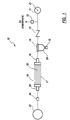
- a dehumidifier system is illustrated and generally designated by a reference numeral 10.
- This system will be described herein with specific reference to the dehumidification of air, but it will be understood that the system is generally applicable to the dehumidification of other gases or gas mixtures such as hydrogen, carbon dioxide, carbon monoxide, helium, nitrogen, oxygen, argon, hydrogen sulfide, nitronic oxides, ammonia, and hydrocarbons of one to five carbon atoms such as methane, ethane and propane.
- An air compressor or pump 11 pressurizes air from the atmosphere which enters the compressor 11 through an inlet 21.
- the pressurized air delivered by the compressor 11 is routed past a restrictive device 12, through a check valve 13 and a filtration device 14 with a drain 15 and to a membrane cartridge 17.
- the membrane cartridge 17 removes moisture from the pressurized air and routes the dehumidified air through a restrictive device 20 to the inlet of a dry air system 22.
- the membrane cartridge 17 utilizes hollow fiber membranes 18 to separate water vapor from air and expel it from the cartridge as water vapor.
- the hollow fiber membranes 18 allow certain gases to permeate through the fiber and escape, while other gases continue through the hollow portion of the fiber.
- the hollow fiber membranes 18 extend from a cartridge inlet 16 to a cartridge outlet 26 so that only air which travels within the hollows of the fibers 18 is available for induction into the dry air system 22. Gases, such as water vapor, which permeate through the walls of the fibers, exit the cartridge 17 through a weep hole 19.
- the preferred membrane cartridge is commercially sold under the tradename "Prism Cactus" by Permea Inc., Malvern Industrial Park, Box 396, Malvern, Pa. 19355.
- a Permea membrane cartridge Model PPC21 is used.
- gases such as water vapor, hydrogen, helium and carbon dioxide permeate the fiber membrane quickly, while gases such as carbon monoxide, nitrogen and methane permeate the fiber membrane slowly. Therefore, more gases, and greater quantities, are filtered out of air as the air spends more time within the membrane cartridge 17. Consequently, as the air spends more time within the membrane cartridge, the air becomes more dehumidified, and the dew point of the air decreases.
- the present invention permits decreases in air flow and system pressure due to increased elevation while providing dehumidified air with the desired dew point.
- the decrease in air flow increases the residence time of the air within the membrane cartridge, resulting in drier air and a reduced dew point in the dehumidified air.
- the pressurized air from the compressor 11 flows past a restrictive device such as an orifice 12 which releases excessive air flow from the compressor to the atmosphere.
- the orifice 12 may be adjusted manually during assembly to account for differences among compressors. Excessive flow rates result in elevated dew points for the dehumidified air because the air spends less time within the membrane cartridge 17.
- a check valve 13 prevents the loss of dehumidified air by allowing air to pass from the compressor 11 to the membrane cartridge 17 but not in the reverse direction, from the membrane cartridge 17 to the compressor 11.
- the pressurized air then enters the filtration device 14 that removes liquid water from the air. The liquid water is removed from the air to prevent it from possibly saturating the fiber membranes 18 within the membrane cartridge 17.
- Saturated fiber membranes cannot filter water vapor from the air, and thus removal of the liquid water prolongs the efficient operation of the membrane cartridge 17.
- the removed water drips into a bowl 24 and is drained from the bowl 24 through a drain 15.
- the drain 15 preferably includes an automatic float valve so that it is opened only during those intervals when water is being removed from the filter. This design allows for a smaller size compressor 11 by securing the system from unnecessary losses of pressurized air.
- a restrictive device 20 such as an orifice is connected to the dehumidified air outlet 26 to link the system pressure and the flow rate together such that the flow rate and pressure combination produce dehumidified air having a desired dew point.
- the dehumidifier 10 With the correct size restrictive device 20, compressor 11 and membrane cartridge 17, the dehumidifier 10 will regulate itself because pressure changes will follow flow rate changes in the desired proportion such that the resulting combination of pressure and flow rate produces dehumidified air having the desired dew point temperature.
- a preferred embodiment of the present invention uses a 0,3 mm (.014 inch) orifice.
- the system pressure decreases because the system pressure and the flow rate are linked by the restrictive device 20.
- the system pressure decrease tends to lower the operating efficiency of the membrane cartridge, but the flow rate decrease increases the residence time of the air within the membrane cartridge.
- the increased residence time of the air within the membrane cartridge lowers the dew point of the dehumidified air and compensates for the decreased efficiency of the membrane cartridge so that the dew point of the dehumidified air is not adversely affected.
- the present invention must be designed so that the system pressure and flow rate follow each other properly in order for the dehumidifier to consistently produce air with the proper dew point. For example, if air flow decreases slightly but system pressure drastically falls, the increased residence time of the air within the membrane cartridge will not compensate for the inefficiency of the membrane cartridge at the low pressure, and the dew point of the dehumidified air will rise.
- a dehumidifier that uses a compressor for its air source will experience a decrease in compressor output flow rates with increasing elevation.
- a typical reciprocating oil-less compressor will develop its rated output flow rate at sea level but only half of its rated output flow rate at an elevation of 10,000 feet, at a given pressure. Due to these flow rate losses, previous dehumidifiers that operated with a constant flow rate required a compressor capable of producing about double the flow rate required at sea level, to enable the same system to operate satisfactorily at 3000 m (10,000 feet).
- the present invention can utilize a smaller compressor with lower output flow rates because the system does not require constant pressure and flow rate.
- the use of a smaller compressor not only reduces cost but also increases reliability and provides a more compact and light weight dehumidifier.
- a Thomas compressor Model #607 is used.
- the present invention regulates itself so that these decreases in system pressure and flow rate do not adversely affect the dew point of the dehumidified air.
- the dehumidifier of the present invention requires fewer components because the present invention does not require constant pressure or flow rate regulation. Fewer components result in lower assembly costs and higher reliability. In fact, the self-regulating nature of the present dehumidifier improves system reliability because minor defects in the dehumidifier that cause output flow loss, such as leaks or compressor wear, do not adversely effect the operation of the present invention. If the dehumidifier of the present invention experiences a small unexpected loss of output flow due to leaks or other damage to the dehumidifier, the present invention will maintain an acceptable dew point for the dehumidified air entering the dry air system 22 because the loss of air flow will increase the residence time of the air within the membrane cartridge 11.
- the supply pressure, the flow rate and the size of the membrane cartridge are selected to supply a particular dry air system 22 with dehumidified air having the desired dew point.
- the present invention allows the decrease of the flow rate and system pressure while still providing dehumidified air at the appropriate dew point for the dry air system 22.
- the dry air system 22 is a tightly sealed system, such as a waveguide system (or other signal transmission media), so that the induction of the pressurized dehumidified air pressurizes the system 22.
- a pressurized system prevents humid atmospheric air from seeping into the system 22, thereby preserving the low humidity level of the air. Since the dehumidified air cannot rapidly escape from the sealed system 22, the compressor 11 does not need to operate continuously in order to effectively dehumidify the air contained within the system 22. Therefore, in order to optimize the efficiency of the dehumidifier 10, the compressor 11 is operated intermittently. This intermittent operation may be cyclical, using a simple control which automatically switches the compressor 11 on and off at regular time intervals. Alternately, a pressure sensor within the dry air system 22 can trigger the switching on and off of compressor 11.
- the present invention has been described with particular reference to controlling the dew point of air, the invention is also applicable to other gases or gas mixtures such as hydrogen, carbon dioxide, carbon monoxide, helium, nitrogen, oxygen, argon, hydrogen sulfide, nitronic oxides, ammonia , and hydrocarbons of one to five carbon atoms such as methane, ethane and propane.
- gases or gas mixtures such as hydrogen, carbon dioxide, carbon monoxide, helium, nitrogen, oxygen, argon, hydrogen sulfide, nitronic oxides, ammonia , and hydrocarbons of one to five carbon atoms such as methane, ethane and propane.
- the cartridge 17 must be provided with a different membrane 18 and/or treatments for certain of these gases, as described for example in U.S. Pat. Nos. 4,230,463; 4,472,175; 4,486,202; 4,575,385; 4,597,777; 4,614,524; 4,654,055 and 4,728,34
Landscapes
- Chemical & Material Sciences (AREA)
- Engineering & Computer Science (AREA)
- Analytical Chemistry (AREA)
- General Chemical & Material Sciences (AREA)
- Oil, Petroleum & Natural Gas (AREA)
- Chemical Kinetics & Catalysis (AREA)
- Mechanical Engineering (AREA)
- General Engineering & Computer Science (AREA)
- Drying Of Gases (AREA)
- Separation Using Semi-Permeable Membranes (AREA)
Description
Claims (26)
- An apparatus (10) for producing dehumidified air and maintaining a desired dew point for said dehumidified air that is suitable for a dry air system including a membrane cartridge (17) having an air inlet (16) where air enters said membrane cartridge (17), said membrane cartridge (17) including a membrane (18) that removes water vapor or other fluid from the air that enters said membrane cartridge (17) through said air inlet (16) and passes dehumidified air through a dehumidified air outlet (26) where said dehumidified air is expelled from said membrane cartridge and further including a fluid exit (19) where water vapor or other fluid is expelled from said membrane cartridge; andcharacterized in thata source (11) of pressurized air connected to said air inlet of said membrane cartridge (17);said apparatus being operable at altitudes of up to 3,000m (10,000 feet) to produce said dehumidified air at said desired dew point;said source (11) supplying pressurized air to said air inlet of said membrane cartridge at a system pressure and flow rate that varies in relation to the altitude and associated ambient pressure in which said apparatus is operated, said system pressure and flow rate being permitted to fluctuate in response to changes in said ambient pressure; anda restrictive device (20) is connected to said dehumidified air outlet for linking said system pressure and said flow rate together such that changes in said system pressure are followed in a desired relationship by changes in said flow rate, said changes producing a proper combination of said pressure and said flow rate for maintaining the dew point of said dehumidified air below a preselected temperature regardless of changes in operating altitude and associated changes in ambient pressure.
- The apparatus of claim 1 wherein said source of pressurized air (11) is a compressor.
- The apparatus of claim 1 further comprising an orifice (12) positioned between said source of pressurized air (11) and said air inlet (16) of said membrane cartridge (17) for releasing excess pressurized air from said apparatus before said pressurized air is supplied to said air inlet (16) of said membrane cartridge (17), said pressurized air being provided to said membrane cartridge (17) at a system pressure and flow rate that varies in relation to the altitude and associated ambient pressure in which said apparatus (10) is operated, said system pressure and flow rate being permitted to fluctuate in response to changes in said ambient pressure.
- The apparatus of claim 1 wherein said restrictive device (20) includes an orifice.
- The apparatus of claim 1 that includes a filtration device connected to said source of pressurized air that filters fluids from said pressurized air before said pressurized air enters said membrane cartridge, said filtration device including a drain for expelling water accumulated from said filtration device, said water being expelled from said filtration device regardless of changes in system pressure.
- The apparatus of claim 1 wherein said filtration device (14) does not consume excessive air flow from said source of pressurized air.
- The apparatus of claim 6 wherein said drain (15) includes an automatic float valve for opening said drain only when fluids are accumulated from said filtration device (14).
- The apparatus of claim 6 further comprising a fixed bleed orifice for removing fluid collected in said filtration device.
- The apparatus of claim 1 that includes valve means (13) positioned between said source of pressurized air (11) and said air inlet (16) of said membrane cartridge, said valve means preventing the flow of dehumidified air back towards the source of pressurized air.
- An apparatus (10) for producing dehumidified air and maintaining a desired dew point for said dehumidified air that is suitable for a dry air system, including a membrane cartridge (17) having an air inlet (16) where air enters said membrane cartridge (17), said membrane cartridge (17) including a membrane (18) that removes water vapor or other fluid from the air that enters said membrane cartridge (17) through said air inlet (16) and passes dehumidified air through a dehumidified air outlet (26) where said dehumidified air is expelled from said membrane cartridge (17) and further including a fluid exit (19) where water vapor or other fluid is expelled from said membrane cartridge; andcharacterized in thata source of pressurized air (11);said apparatus being operable at altitudes of up to 3,000m (10,000 feet) to produce said dehumidified air at said desired dew point;said source of pressurized air (11) is adapted for supplying pressurized air to said apparatus at an output pressure and flow rate that varies in relation to the altitude and associated ambient pressure in which said apparatus is operated;an orifice (12) located between said source of pressurized air (11) and said air inlet (16) of said membrane cartridge (17) for releasing excess pressurized air from said apparatus (10) before said pressurized air is supplied to said air inlet of said membrane cartridge (17), said pressurized air being provided to said membrane cartridge (17) at a system pressure and flow rate that varies in relation to the altitude and associated ambient pressure in which said apparatus is operated, said system pressure and flow rate being permitted to fluctuate in response to changes in said ambient pressure; anda restrictive device (20) connected to said dehumidified air outlet for linking said system pressure and said flow rate together such that changes in said system pressure are followed in a desired relationship by changes in said flow rate, said changes producing a proper combination of said pressure and said flow rate for maintaining the dew point of said dehumidified air below a preselected temperature regardless of changes in operating altitude and associated changes in ambient pressure.
- The apparatus of claim 10 wherein said source of pressurized air is a compressor.
- The apparatus of claim 10 wherein said restrictive device (20) includes an orifice.
- The apparatus of claim 10 that includes a filtration device (14) connected to said source of pressurized air that filters fluids from said pressurized air before said pressurized air enters said membrane cartridge, said filtration device (14) including a drain for expelling water accumulated from said filtration device, said water being expelled from said filtration device regardless of changes in system pressure.
- The apparatus of claim 13 wherein said filtration device (14) does not consume excessive air flow from said source of pressurized air.
- The apparatus of claim 14 wherein said drain (15) includes an automatic float valve for opening said drain only when fluids are accumulated from said filtration device.
- The apparatus of claim 14 further comprising a fixed bleed orifice for removing fluid collected in said filtration device (14).
- The apparatus of claim 10 that includes valve means (13) positioned between said source of pressurized air (11) and said air inlet (16) of said membrane cartridge (17), said valve means preventing the flow of dehumidified air back towards said source of pressurized air.
- A method for producing dehumidified air and maintaining a suitable dew point for said dehumidified air for a dry air system, comprising the steps of:characterized bysupplying pressurized air to be dehumidified;passing the air to be dehumidified through a membrane cartridge (17) having a membrane (18) that removes water vapor or other fluid from the air that enters said membrane cartridge (17) through an air inlet, said membrane cartridge (17) having a dehumidified air outlet where said dehumidified air is expelled from said membrane cartridge and further including a fluid exit (19) where water vapor or other fluid is expelled from said membrane cartridge;controlling varying flow rate versus pressure characteristics for said pressurized air entering said membrane cartridge (17) by permitting changes in said pressure and said flow rate such that said changes in said pressure and said flow rate follow each other in a desired relationship to produce a proper combination of said pressure and said flow rate for maintaining the dew point of said dehumidified air below a preselected temperature regardless of said changes.
- The method of claim 18 wherein said step of supplying pressurized air includes the use of a compressor (11).
- The method of claim 18 wherein a secondary restrictive device (12) connected to said air inlet of said membrane cartridge releases excess pressurized air.
- The method of claim 18 wherein the step of controlling further comprises utilizing a primary restrictive device (20) connected to said dehumidified air outlet (26) for producing the proper combination of said flow rate and said pressure for maintaining the desired dew point.
- The method of claim 21 wherein the step of controlling varying flow rate versus pressure characteristics includes releasing excess pressurized air with a secondary restrictive device connected to said air inlet of said membrane cartridge (17).
- The method of claim 22 which includes the step of filtering fluids from said pressurized air before said pressurized air passes through said membrane cartridge (17).
- The method of claim 23 which includes the step of draining said fluids accumulated from said step of filtering fluids from said pressurized air.
- The method of claim 24 in which the step of draining said fluids includes using an automatic float drain.
- The method of claim 24 in which the step of draining said fluids includes using a fixed bleed orifice for removing fluid from said filtration device.
Applications Claiming Priority (2)
| Application Number | Priority Date | Filing Date | Title |
|---|---|---|---|
| US07/981,191 US5762690A (en) | 1992-11-25 | 1992-11-25 | Dehumidifier for supplying air using variable flow rate and variable pressure in a membrane dryer |
| US981191 | 1992-11-25 |
Publications (3)
| Publication Number | Publication Date |
|---|---|
| EP0599149A2 EP0599149A2 (en) | 1994-06-01 |
| EP0599149A3 EP0599149A3 (en) | 1995-03-08 |
| EP0599149B1 true EP0599149B1 (en) | 1998-06-10 |
Family
ID=25528189
Family Applications (1)
| Application Number | Title | Priority Date | Filing Date |
|---|---|---|---|
| EP93118293A Expired - Lifetime EP0599149B1 (en) | 1992-11-25 | 1993-11-11 | Dehumidifier for supplying air using variable flow rate and variable pressure in a membrane dryer |
Country Status (6)
| Country | Link |
|---|---|
| US (2) | US5762690A (en) |
| EP (1) | EP0599149B1 (en) |
| JP (1) | JP3683287B2 (en) |
| AU (1) | AU664776B2 (en) |
| CA (1) | CA2102393C (en) |
| DE (1) | DE69319069T2 (en) |
Families Citing this family (21)
| Publication number | Priority date | Publication date | Assignee | Title |
|---|---|---|---|---|
| AUPM592694A0 (en) * | 1994-05-30 | 1994-06-23 | F F Seeley Nominees Pty Ltd | Vacuum dewatering of desiccant brines |
| JP3462854B2 (en) * | 1998-06-17 | 2003-11-05 | 都孝 溝部 | Airtightness inspection method and airtightness inspection device for closed space with water vapor transfer control device |
| US6126724A (en) * | 1999-02-19 | 2000-10-03 | Hansen Inc. | Locomotive air processing apparatus |
| NL1011626C2 (en) | 1999-03-22 | 2000-09-27 | Kema Nv | Preparation of water from flue gases. |
| JP2001070739A (en) * | 1999-09-03 | 2001-03-21 | Nabco Ltd | Compressed air dehumidifier, compressed air dehumidifing apparatus and remodeling system of them |
| US6491739B1 (en) * | 1999-11-09 | 2002-12-10 | Litton Systems, Inc. | Air separation module using a fast start valve for fast warm up of a permeable membrane air separation module |
| US6705092B1 (en) * | 2001-11-14 | 2004-03-16 | Honeywell International Inc. | Vapor membrane dehumidification for air cycle environment control system |
| US6719825B2 (en) * | 2002-05-07 | 2004-04-13 | Graham-White Manufacturing Company | Air drying apparatus and method |
| US6764529B2 (en) * | 2002-07-01 | 2004-07-20 | Bendix Commercial Vehicle Systems Llc | Membrane gas dehydrating apparatus for gas controlled and powered systems |
| US6923845B2 (en) * | 2002-10-18 | 2005-08-02 | Bendix Commercial Vehicle Systems Llc | Membrane air dryer for vehicle air brake system |
| US6881245B2 (en) * | 2002-10-18 | 2005-04-19 | Bendix Commercial Vehicle Systems Llc | Membrane air dryer and method of mounting a membrane dryer to a vehicle |
| FR2862129A1 (en) * | 2003-11-07 | 2005-05-13 | Olivier Kaelbel | Granulated thermoplastic material drying process for injection machine, involves circulating compressed air via filtration units then via membrane separator of drying units, expanding dry air from separator and heating air |
| DE102004022312B4 (en) * | 2004-05-04 | 2009-04-16 | Daimler Ag | Moisture exchange module with a bundle of moisture permeable hollow fiber membranes |
| US20110077605A1 (en) * | 2005-07-14 | 2011-03-31 | Boehringer Technologies, L.P. | Pump system for negative pressure wound therapy |
| US7481869B2 (en) * | 2005-08-17 | 2009-01-27 | Andrew Llc | Dry gas production systems for pressurizing a space and methods of operating such systems to produce a dry gas stream |
| US7678177B2 (en) * | 2006-09-12 | 2010-03-16 | New York Air Brake Corporation | Membrane air dryer and sweep valve |
| JP5668269B2 (en) * | 2007-01-30 | 2015-02-12 | Smc株式会社 | Dehumidification air system |
| JP5982876B2 (en) * | 2012-02-29 | 2016-08-31 | 宇部興産株式会社 | Gas separation system |
| JP2014091766A (en) * | 2012-11-01 | 2014-05-19 | Ube Ind Ltd | System for utilizing biogas, and method for dehumidifying biogas |
| US10144036B2 (en) * | 2015-01-30 | 2018-12-04 | At&T Intellectual Property I, L.P. | Method and apparatus for mitigating interference affecting a propagation of electromagnetic waves guided by a transmission medium |
| US11619405B1 (en) | 2022-01-27 | 2023-04-04 | Greg Drenik | Airflow moisture reduction system |
Citations (1)
| Publication number | Priority date | Publication date | Assignee | Title |
|---|---|---|---|---|
| US5118327A (en) * | 1989-10-05 | 1992-06-02 | Andrew Corporation | Dehumidifier for supplying gas having controlled dew point |
Family Cites Families (69)
| Publication number | Priority date | Publication date | Assignee | Title |
|---|---|---|---|---|
| US2779173A (en) * | 1955-04-25 | 1957-01-29 | Gen Motors Corp | Dehumidifier having unitary evaporator-condenser plate |
| NL271831A (en) * | 1960-11-29 | |||
| US3499062A (en) * | 1965-12-22 | 1970-03-03 | Du Pont | Method of repairing leaks in fluid separation apparatus |
| US3536611A (en) * | 1967-02-06 | 1970-10-27 | Abcor Inc | Membrane device and method |
| US3511031A (en) * | 1968-03-19 | 1970-05-12 | Little Inc A | Apparatus for removing water vapor from gases |
| US3556305A (en) * | 1968-03-28 | 1971-01-19 | Amicon Corp | Composite membrane and process for making same |
| US3615024A (en) * | 1968-08-26 | 1971-10-26 | Amicon Corp | High flow membrane |
| DE1919290B2 (en) * | 1969-04-16 | 1980-06-19 | Schantz, Hugo, Dipl.-Ing., 7064 Remshalden | Room air dehumidification system - uses additional condenser unit, switched in parallel with main unit via changeover valves |
| US3556992A (en) * | 1969-07-22 | 1971-01-19 | Amicon Corp | Anisotropic ultrafiltration membrane having adhering coating and methods of forming and using this membrane |
| US3580841A (en) * | 1969-07-31 | 1971-05-25 | Us Interior | Ultrathin semipermeable membrane |
| US3657113A (en) * | 1970-02-03 | 1972-04-18 | Mobil Oil Corp | Separating fluids with selective membranes |
| US3616607A (en) * | 1970-04-06 | 1971-11-02 | Northern Natural Gas Co | Separation of nitrogen and methane containing gas mixtures |
| US3676203A (en) * | 1970-08-07 | 1972-07-11 | Us Interior | Semipermeable membranes |
| US3735558A (en) * | 1971-06-29 | 1973-05-29 | Perma Pure Process Inc | Process for separating fluids and apparatus |
| US3775303A (en) * | 1971-12-08 | 1973-11-27 | Gulf Research Development Co | Production of low sulfur asphaltic fuel oil |
| US3735559A (en) * | 1972-02-02 | 1973-05-29 | Gen Electric | Sulfonated polyxylylene oxide as a permselective membrane for water vapor transport |
| US3822202A (en) * | 1972-07-20 | 1974-07-02 | Du Pont | Heat treatment of membranes of selected polyimides,polyesters and polyamides |
| US3892665A (en) * | 1973-10-15 | 1975-07-01 | Standard Oil Co | Membrane method and product |
| US3922149A (en) * | 1974-01-30 | 1975-11-25 | Garrett Corp | Oxygen air enrichment method |
| US4142966A (en) * | 1974-04-01 | 1979-03-06 | Monsanto Company | Membrane separation of water from aqueous mixtures |
| US3874986A (en) * | 1974-05-20 | 1975-04-01 | Gen Electric | Laminated porous/non-porous membranes |
| US3930814A (en) * | 1974-11-27 | 1976-01-06 | General Electric Company | Process for producing oxygen-enriched gas |
| US4108765A (en) * | 1975-12-01 | 1978-08-22 | Monsanto Company | Membrane separation of methanol from formaldehyde aqueous mixtures |
| US4311594A (en) * | 1975-12-01 | 1982-01-19 | Monsanto Company | Membrane separation of organics from aqueous solutions |
| US4230463A (en) * | 1977-09-13 | 1980-10-28 | Monsanto Company | Multicomponent membranes for gas separations |
| FR2403819A1 (en) * | 1977-09-27 | 1979-04-20 | Ravier Philippe | GAS SEPARATION PROCESS AND INSTALLATION BY GAS DIFFUSION |
| US4157960A (en) * | 1977-11-30 | 1979-06-12 | Monsanto Company | Method for enhancing membrane separation |
| JPS5687417A (en) * | 1979-12-14 | 1981-07-16 | H Ii I:Kk | Exchanger for heat and/or humidity |
| US4397661A (en) * | 1980-06-27 | 1983-08-09 | Monsanto Company | Gas permeation apparatus having permeate rate controlled valving |
| BR8107040A (en) * | 1980-11-03 | 1982-07-20 | Monsanto Co | PROCESS TO SEPARATE A GAS MIXTURE IN GAS AND AT LEAST ONE OTHER GAS AND PROCESS FOR HYDROGEN RECOVERY FROM A GAS CHAIN |
| US4421529A (en) * | 1982-07-02 | 1983-12-20 | The Dow Chemical Company | Membrane system for intermittent gas separation |
| FR2540396B1 (en) * | 1983-02-04 | 1988-09-23 | Petroles Cie Francaise | GAS DEHYDRATION PROCESS |
| US4597777A (en) * | 1983-02-15 | 1986-07-01 | Monsanto Company | Membrane gas separation processes |
| US4654055A (en) * | 1983-06-30 | 1987-03-31 | Monsanto Company | Asymmetric gas separation membranes |
| US4486202A (en) * | 1983-06-30 | 1984-12-04 | Monsanto Company | Asymmetric gas separation membranes |
| US4575385A (en) * | 1983-06-30 | 1986-03-11 | Monsanto Company | Permeation modified gas separation membranes |
| US4472175A (en) * | 1983-06-30 | 1984-09-18 | Monsanto Company | Asymmetric gas separation membranes |
| JPS6099328A (en) * | 1983-11-04 | 1985-06-03 | Toyota Central Res & Dev Lab Inc | Separating apparatus for condensable gas |
| SU1271522A1 (en) * | 1983-11-09 | 1986-11-23 | Саратовский Государственный Ордена Трудового Красного Знамени Медицинский Институт | Method of differential diagnosis of tuberculosis and nonspecific diseases of the lungs |
| US4728345A (en) * | 1983-12-28 | 1988-03-01 | Monsanto Company | Multicomponent gas separation membranes having polyphosphazene coatings |
| JPS60238119A (en) * | 1984-05-10 | 1985-11-27 | Takuma Sogo Kenkyusho:Kk | Air dehumidification apparatus |
| US4549888A (en) * | 1984-11-07 | 1985-10-29 | Allied Corporation | Automatic control for an external air supply |
| JPH0114780Y2 (en) * | 1984-11-20 | 1989-04-28 | ||
| US4614524A (en) * | 1984-12-31 | 1986-09-30 | Monsanto Company | Water-free hydrocarbon separation membrane and process |
| EP0192143B1 (en) * | 1985-02-09 | 1996-01-10 | Asahi Kasei Kogyo Kabushiki Kaisha | Permeable polymer membrane for desiccation of gas |
| JPS6242723A (en) * | 1985-08-20 | 1987-02-24 | Ube Ind Ltd | Method for dehumidifying mixed gas |
| US4687578A (en) * | 1985-12-12 | 1987-08-18 | Monsanto Company | Fluid separation membranes |
| JPS62191404A (en) * | 1986-02-19 | 1987-08-21 | Hitachi Ltd | Air separation apparatus |
| JPH07110330B2 (en) * | 1986-05-20 | 1995-11-29 | 旭化成工業株式会社 | Gas dehumidification method |
| EP0263212B1 (en) * | 1986-10-08 | 1990-12-27 | Ube Industries, Ltd. | Method for removing water vapor from water vapor-containing gas |
| JPS63123421A (en) * | 1986-11-10 | 1988-05-27 | Kuraray Co Ltd | Dehumidified air feeder |
| JPS63123422A (en) * | 1986-11-11 | 1988-05-27 | Kuraray Co Ltd | Dehumidified air feeder |
| JPH0762550B2 (en) * | 1986-12-26 | 1995-07-05 | 株式会社東芝 | Air conditioner |
| JPS63236517A (en) * | 1987-03-24 | 1988-10-03 | Ube Ind Ltd | Dehumidification method for mixed gas |
| JPS63296819A (en) * | 1987-05-28 | 1988-12-02 | Matsushita Electric Ind Co Ltd | Method for enriching gas supplied to chamber |
| US4806132A (en) * | 1987-06-23 | 1989-02-21 | Union Carbide Corporation | Turndown control method for membrane separation systems |
| US4783201A (en) * | 1987-12-28 | 1988-11-08 | Rice Arthur W | Gas dehydration membrane apparatus |
| US4857082A (en) * | 1988-09-15 | 1989-08-15 | Air Products And Chemicals, Inc. | Membrane unit turn-down control system |
| US4863492A (en) * | 1988-11-28 | 1989-09-05 | Uop | Integrated membrane/PSA process and system |
| GB8916510D0 (en) * | 1989-07-19 | 1989-09-06 | Boc Group Plc | Separation of gas mixtures |
| US5108464A (en) * | 1989-09-19 | 1992-04-28 | Bend Research, Inc. | Countercurrent dehydration by hollow fibers |
| US4944776A (en) * | 1989-10-05 | 1990-07-31 | Andrew Corporation | Dehumidifier for waveguide system |
| US5030251A (en) * | 1989-10-30 | 1991-07-09 | Permea, Inc. | System and method for separating a portion of a gas from a mixture of gases |
| US5129924A (en) * | 1989-12-29 | 1992-07-14 | Jerald Schultz | Supplemental oxygen ventilator |
| US5053058A (en) * | 1989-12-29 | 1991-10-01 | Uop | Control process and apparatus for membrane separation systems |
| US5131929A (en) * | 1991-05-06 | 1992-07-21 | Permea, Inc. | Pressure control for improved gas dehydration in systems which employ membrane dryers in intermittent service |
| US5281253A (en) * | 1993-01-06 | 1994-01-25 | Praxair Technology, Inc. | Multistage membrane control system and process |
| DE4435702C2 (en) * | 1994-10-06 | 1998-11-26 | Druckluft Dannoehl Gmbh | Method and device for producing nitrogen |
| US5681368A (en) * | 1995-07-05 | 1997-10-28 | Andrew Corporation | Dehumidifier system using membrane cartridge |
-
1992
- 1992-11-25 US US07/981,191 patent/US5762690A/en not_active Expired - Lifetime
-
1993
- 1993-11-03 CA CA002102393A patent/CA2102393C/en not_active Expired - Lifetime
- 1993-11-10 AU AU50591/93A patent/AU664776B2/en not_active Expired
- 1993-11-11 DE DE69319069T patent/DE69319069T2/en not_active Expired - Lifetime
- 1993-11-11 EP EP93118293A patent/EP0599149B1/en not_active Expired - Lifetime
- 1993-11-24 JP JP29319193A patent/JP3683287B2/en not_active Expired - Lifetime
-
1997
- 1997-11-24 US US08/976,887 patent/US5885329A/en not_active Expired - Lifetime
Patent Citations (1)
| Publication number | Priority date | Publication date | Assignee | Title |
|---|---|---|---|---|
| US5118327A (en) * | 1989-10-05 | 1992-06-02 | Andrew Corporation | Dehumidifier for supplying gas having controlled dew point |
Also Published As
| Publication number | Publication date |
|---|---|
| JP3683287B2 (en) | 2005-08-17 |
| CA2102393C (en) | 2000-06-06 |
| DE69319069T2 (en) | 1998-10-08 |
| AU5059193A (en) | 1994-06-09 |
| EP0599149A2 (en) | 1994-06-01 |
| DE69319069D1 (en) | 1998-07-16 |
| US5885329A (en) | 1999-03-23 |
| US5762690A (en) | 1998-06-09 |
| CA2102393A1 (en) | 1994-05-26 |
| EP0599149A3 (en) | 1995-03-08 |
| AU664776B2 (en) | 1995-11-30 |
| JPH06218220A (en) | 1994-08-09 |
Similar Documents
| Publication | Publication Date | Title |
|---|---|---|
| EP0599149B1 (en) | Dehumidifier for supplying air using variable flow rate and variable pressure in a membrane dryer | |
| US5681368A (en) | Dehumidifier system using membrane cartridge | |
| US5118327A (en) | Dehumidifier for supplying gas having controlled dew point | |
| EP0421402B1 (en) | Gas dehumidifier and gas dehumidification process | |
| AU749819B2 (en) | Membrane air dryer with scheme to reduce air lost as sweep air | |
| US6128825A (en) | Combination main reservoir and gas drying apparatus | |
| US5605564A (en) | Membrane gas dehydrator | |
| US5383956A (en) | Start-up and shut down processes for membrane systems and membrane systems useful for the same | |
| EP1235631A1 (en) | Compressed gas systems utilizing a variable pressure membrane air drier, and method of operation thereof | |
| US20090049983A1 (en) | Energy management system for membrane separation device | |
| KR20070087548A (en) | Membrane-based reservoir dryer | |
| CN208519862U (en) | Purify constant humidity system | |
| RU2133513C1 (en) | Plant for holding telephone cables under gage pressure | |
| EP3574977B1 (en) | Gas dehydration membrane module with integral filter | |
| RU2056689C1 (en) | Plant for keeping gas-filled cables under gage pressure | |
| JP4451770B2 (en) | Gas-liquid separator and analyzer using the same | |
| RU2233698C1 (en) | Method and device for separating and/or drying gas mixtures | |
| JP2000334253A (en) | Compressed air supply device for station service | |
| RU2171513C1 (en) | Arrangement for holding telephone and gas-filled power cables under gage pressure | |
| JPH062734Y2 (en) | Dehumidifier | |
| RU2107962C1 (en) | Plant for keeping cables of urban telephone lines under gage pressure | |
| JP3372212B2 (en) | Membrane gas dryer | |
| MXPA99009718A (en) | Membrane air dryer that has a regulation reduces air loss as barr air |
Legal Events
| Date | Code | Title | Description |
|---|---|---|---|
| PUAI | Public reference made under article 153(3) epc to a published international application that has entered the european phase |
Free format text: ORIGINAL CODE: 0009012 |
|
| AK | Designated contracting states |
Kind code of ref document: A2 Designated state(s): DE FR GB IT NL |
|
| PUAL | Search report despatched |
Free format text: ORIGINAL CODE: 0009013 |
|
| AK | Designated contracting states |
Kind code of ref document: A3 Designated state(s): DE FR GB IT NL |
|
| 17P | Request for examination filed |
Effective date: 19950608 |
|
| 17Q | First examination report despatched |
Effective date: 19961218 |
|
| GRAG | Despatch of communication of intention to grant |
Free format text: ORIGINAL CODE: EPIDOS AGRA |
|
| GRAG | Despatch of communication of intention to grant |
Free format text: ORIGINAL CODE: EPIDOS AGRA |
|
| GRAH | Despatch of communication of intention to grant a patent |
Free format text: ORIGINAL CODE: EPIDOS IGRA |
|
| GRAH | Despatch of communication of intention to grant a patent |
Free format text: ORIGINAL CODE: EPIDOS IGRA |
|
| GRAA | (expected) grant |
Free format text: ORIGINAL CODE: 0009210 |
|
| AK | Designated contracting states |
Kind code of ref document: B1 Designated state(s): DE FR GB IT NL |
|
| REF | Corresponds to: |
Ref document number: 69319069 Country of ref document: DE Date of ref document: 19980716 |
|
| ITF | It: translation for a ep patent filed |
Owner name: JACOBACCI & PERANI S.P.A. |
|
| ET | Fr: translation filed | ||
| PLBE | No opposition filed within time limit |
Free format text: ORIGINAL CODE: 0009261 |
|
| STAA | Information on the status of an ep patent application or granted ep patent |
Free format text: STATUS: NO OPPOSITION FILED WITHIN TIME LIMIT |
|
| 26N | No opposition filed | ||
| REG | Reference to a national code |
Ref country code: GB Ref legal event code: IF02 |
|
| PGFP | Annual fee paid to national office [announced via postgrant information from national office to epo] |
Ref country code: DE Payment date: 20121128 Year of fee payment: 20 Ref country code: FR Payment date: 20121206 Year of fee payment: 20 |
|
| PGFP | Annual fee paid to national office [announced via postgrant information from national office to epo] |
Ref country code: GB Payment date: 20121126 Year of fee payment: 20 Ref country code: IT Payment date: 20121126 Year of fee payment: 20 |
|
| PGFP | Annual fee paid to national office [announced via postgrant information from national office to epo] |
Ref country code: NL Payment date: 20121124 Year of fee payment: 20 |
|
| REG | Reference to a national code |
Ref country code: DE Ref legal event code: R071 Ref document number: 69319069 Country of ref document: DE |
|
| REG | Reference to a national code |
Ref country code: NL Ref legal event code: V4 Effective date: 20131111 |
|
| REG | Reference to a national code |
Ref country code: GB Ref legal event code: PE20 Expiry date: 20131110 |
|
| PG25 | Lapsed in a contracting state [announced via postgrant information from national office to epo] |
Ref country code: GB Free format text: LAPSE BECAUSE OF EXPIRATION OF PROTECTION Effective date: 20131110 Ref country code: DE Free format text: LAPSE BECAUSE OF EXPIRATION OF PROTECTION Effective date: 20131112 |