EP0599080B1 - Soupape de pression résiduelle - Google Patents
Soupape de pression résiduelle Download PDFInfo
- Publication number
- EP0599080B1 EP0599080B1 EP93117542A EP93117542A EP0599080B1 EP 0599080 B1 EP0599080 B1 EP 0599080B1 EP 93117542 A EP93117542 A EP 93117542A EP 93117542 A EP93117542 A EP 93117542A EP 0599080 B1 EP0599080 B1 EP 0599080B1
- Authority
- EP
- European Patent Office
- Prior art keywords
- sealing
- holder
- seat
- pressure valve
- residual
- Prior art date
- Legal status (The legal status is an assumption and is not a legal conclusion. Google has not performed a legal analysis and makes no representation as to the accuracy of the status listed.)
- Expired - Lifetime
Links
- 238000007789 sealing Methods 0.000 claims description 142
- 125000006850 spacer group Chemical group 0.000 claims description 38
- 230000006835 compression Effects 0.000 claims description 22
- 238000007906 compression Methods 0.000 claims description 22
- 230000002093 peripheral effect Effects 0.000 claims description 2
- 238000004519 manufacturing process Methods 0.000 description 3
- 238000010276 construction Methods 0.000 description 2
- 230000004323 axial length Effects 0.000 description 1
- 238000006073 displacement reaction Methods 0.000 description 1
- 238000005429 filling process Methods 0.000 description 1
- 238000012423 maintenance Methods 0.000 description 1
- 238000003801 milling Methods 0.000 description 1
Images


Classifications
-
- F—MECHANICAL ENGINEERING; LIGHTING; HEATING; WEAPONS; BLASTING
- F16—ENGINEERING ELEMENTS AND UNITS; GENERAL MEASURES FOR PRODUCING AND MAINTAINING EFFECTIVE FUNCTIONING OF MACHINES OR INSTALLATIONS; THERMAL INSULATION IN GENERAL
- F16K—VALVES; TAPS; COCKS; ACTUATING-FLOATS; DEVICES FOR VENTING OR AERATING
- F16K1/00—Lift valves or globe valves, i.e. cut-off apparatus with closure members having at least a component of their opening and closing motion perpendicular to the closing faces
- F16K1/30—Lift valves or globe valves, i.e. cut-off apparatus with closure members having at least a component of their opening and closing motion perpendicular to the closing faces specially adapted for pressure containers
- F16K1/307—Additional means used in combination with the main valve
-
- F—MECHANICAL ENGINEERING; LIGHTING; HEATING; WEAPONS; BLASTING
- F17—STORING OR DISTRIBUTING GASES OR LIQUIDS
- F17C—VESSELS FOR CONTAINING OR STORING COMPRESSED, LIQUEFIED OR SOLIDIFIED GASES; FIXED-CAPACITY GAS-HOLDERS; FILLING VESSELS WITH, OR DISCHARGING FROM VESSELS, COMPRESSED, LIQUEFIED, OR SOLIDIFIED GASES
- F17C13/00—Details of vessels or of the filling or discharging of vessels
- F17C13/04—Arrangement or mounting of valves
-
- F—MECHANICAL ENGINEERING; LIGHTING; HEATING; WEAPONS; BLASTING
- F17—STORING OR DISTRIBUTING GASES OR LIQUIDS
- F17C—VESSELS FOR CONTAINING OR STORING COMPRESSED, LIQUEFIED OR SOLIDIFIED GASES; FIXED-CAPACITY GAS-HOLDERS; FILLING VESSELS WITH, OR DISCHARGING FROM VESSELS, COMPRESSED, LIQUEFIED, OR SOLIDIFIED GASES
- F17C2227/00—Transfer of fluids, i.e. method or means for transferring the fluid; Heat exchange with the fluid
- F17C2227/04—Methods for emptying or filling
- F17C2227/048—Methods for emptying or filling by maintaining residual pressure
Definitions
- the invention relates to a residual pressure valve for a gas cylinder valve to be assigned to a compressed gas container according to the features in the preamble of patent claim 1.
- Such a residual pressure valve is part of the prior art through DE-A-2 300 240.
- valve arrangement for a pressurized gas container which prevents its emptying to a pressure below the residual pressure and permits its filling.
- This valve arrangement comprises a sealing body which is fixed to a sealing body carrier in a channel of the valve housing and can be pressed against a resiliently supported sealing seat under the influence of a compression spring.
- the sealing seat is part of a sealing seat carrier.
- the sealing body is centrally embedded in the sealing body carrier in its end face facing the sealing seat, the annular sealing seat carrier of the sealing body carrier being located.
- the sealing body carrier and the sealing seat carrier can be axially displaced together in sections. The displacement is limited by a projecting snap ring, which is located in a groove as a stop for the sealing body carrier.
- a similar residual pressure valve is also known from DE-C-2 920 882.
- the multiply graduated transverse channel is provided in a lateral connection piece of the valve housing and is connected by several bores running eccentrically to the axis of the transverse channel with a gas channel which penetrates the gas cylinder valve in the longitudinal direction and can be closed by a valve body.
- the sealing seat support is designed like a sleeve and is axially sealed in a longitudinal section of the transverse channel via a circumferential sealing ring. Its axial movement is limited on the one hand by a gradation of the transverse channel and on the other hand by a slotted ring which is embedded in a circumferential ring groove in the wall of the longitudinal section. Since the ring groove is wider than the thickness of the slot ring, the slot ring can be moved parallel to itself in the ring groove.
- the longitudinally channeled sealing seat carrier has an annular recess into which a helical compression spring engages. This is based on the one hand on the bottom of the recess and on the other hand on a further gradation of the transverse channel.
- the helical compression spring constantly loads the sealing seat carrier in the direction of the slot ring.
- the circular recess for receiving the helical compression spring is connected to the inner longitudinal channel via transverse slots.
- the sealing seat carrier is used for the axial guidance of the sealing body carrier designed in the manner of a plunger.
- the sealing body carrier is mainly guided in the longitudinal section of the annular recess for the helical compression spring.
- the sealing body carrier has a disk-shaped head.
- the underside of the head is provided with an annular groove in which a sealing ring with an annular cross section is embedded.
- This sealing ring interacts with a sealing edge which is designed as a sealing seat on a radially inwardly projecting collar of the sealing seat carrier.
- a slotted disc is fixed in an appropriately designed annular groove, which forms a support for a further helical compression spring which, on the other hand, is supported on the bottom of the annular recess in the sealing seat carrier.
- a disadvantage of this type of construction is the fact that the sealing seat carrier and the sealing body carrier must be precisely coordinated with one another, because the sealing body carrier is axially positively guided in the sealing seat carrier.
- the length section of the transverse channel in which the sealing seat carrier is positively guided must also be matched exactly to the sealing seat carrier.
- a further disadvantage is the production of the complicatedly designed sealing seat carrier with regard to the annular recess for the two helical compression springs and the transverse slots between the longitudinal channel for guiding the sealing body carrier and the annular recess.
- annular groove receiving the slot ring is disadvantageous. Regardless of whether the slit ring is displaced in the ring groove by a filling adapter, by the sealing seat carrier or by the compressed gas itself, there is always the risk that this slit ring can tilt parallel to itself, so that the function of the residual pressure valve will be annulled.
- the off-center tap holes between the cross channel and the central gas channel in the gas cylinder valve can only be produced with a special effort.
- annular sealing body is directly exposed to the influence of the compressed gas.
- swirls in the compressed gas can easily push the sealing body out of the groove holding it.
- Another disadvantage is that when a filling adapter is used, the passage areas between the wall of the bore in the filling adapter and the outer circumference of the head of the sealing body carrier become very small, and thus an insufficient tread cross section is present.
- the invention is based on the features described in the preamble of claim 1, the task of creating a residual pressure valve that is simple in construction and easy to assemble and has large passage cross sections for the compressed gas in all operating situations.
- the first obvious advantage here is that all moving parts of the residual pressure valve, such as in particular the sealing seat carrier, the sealing body carrier and the spacer sleeve, are arranged axially one behind the other. This permits problem-free production with comparatively large tolerances, without having to take particular account of the assignment of the individual components. All components are designed as normal rotating bodies, on which only in relation to the sealing body carrier and the spacer sleeve, simple milling operations for producing the guide webs on the one hand and the spacer fingers on the other hand must be carried out.
- a further advantage is seen within the scope of the invention in that the sealing body embedded in the end face in the sealing body carrier can interact flat with the sealing seat on the annular sealing seat carrier. As a result, the sealing body in particular is less susceptible to wear. It has a long service life.
- sealing body carrier is supported via the guide webs in the web section of the transverse channel and the spacer fingers forming part of the spacer sleeve are arranged at a large radial distance from the wall of the web section, large passage cross sections are created on the circumference of the sealing body carrier, regardless of whether the compressed gas tank is filled (opening of the residual pressure valve by the compressed gas or a filling adapter) or emptied.
- an advantage of the invention is that it is easy to assemble due to the axial arrangement of the various components, which is also reflected in simple maintenance.
- both the sealing body carrier in the direction of the sealing seat carrier and the sealing seat carrier in the direction of the sealing body carrier are loaded by the spring dimensioning, taking into account the desired residual pressure of, for example, 2.5 bar to 3 bar.
- the spacer sleeve lies against the bottom of the cross channel. Furthermore, the sealing body is pressed against the sealing seat during the sealing body carrier is, so to speak, floating in the web section of the transverse channel without hitting the end faces of the web section.
- the pressurized gas after opening the gas cylinder valve, passes through the cross channel and through the sealing seat carrier to the front side of the sealing body carrier and, together with the sealing body, shifts it against the restoring force of the helical compression spring acting on the sealing body carrier until the sealing body carrier stops on the the end of the web section facing the bottom of the transverse channel.
- the compressed gas can then pass the sealing seat and on the circumferential side of the spacer fingers into the spacer sleeve and flow out from here via the perforations on the bottom of the spacer sleeve and the opening in the bottom of the transverse channel.
- the pressure in the pressure gas container drops to the residual pressure level of e.g. 2.5 bar to 3 bar
- the helical compression springs which load on the sealing body carrier on the one hand and the sealing seat carrier on the other and are adjusted to the desired residual pressure level, cause the sealing body carrier to return to the position in which the sealing body lies sealingly on the sealing seat and the sealing body carrier has a floating position occupies in the web section of the transverse channel.
- the spacer sleeve When filling the pressurized gas container, the spacer sleeve is moved together with the sealing body carrier either only by the filling pressure of the compressed gas or also by an appropriate filling adapter in the direction of the sealing seat carrier until the sealing body carrier comes to rest on the front side of the cross section of the cross channel. But since both the web section and the spacer fingers of the Spacer sleeve are longer than the guide webs of the sealing body section, the sealing seat carrier is also shifted slightly against the restoring force of the helical compression spring loaded on it, so that the pressurized gas from the spacer sleeve over the passage areas on the circumferential side of the spacer fingers and past the sealing seat into the transverse channel in the direction of the pressurized gas container can reach.
- a particularly advantageous embodiment of the invention consists in the features of patent claim 2.
- the advantage is achieved that even small series can be produced economically.
- the features of claim 3 have the purpose that, especially in the closed position of the residual pressure valve, the sealing body and the sealing seat are properly pressed against one another without the guide webs of the sealing body carrier in the web section of the transverse channel being able to stop on the end face.
- the sealing seat support concentrically to the sealing seat receives an annular projection which can come into contact with the spacer fingers of the spacer sleeve perfectly.
- the sealing seat carrier is loaded by a plate spring assembly in the direction of the sealing body carrier.
- this plate spring assembly ensures, by suitable dimensioning of the restoring force of the plate spring assembly, that this restoring force can only be overcome when the special filling adapter is used. Inadmissible tampering with the residual pressure valve is removed from the floor.
- Another advantageous feature of the invention is in claim 6.
- the spacer sleeve and the pressure piece can be manufactured separately.
- the material supply is simplified and the material removal is reduced.
- the sealing body carrier and the spacer sleeve are integrated in a valve cartridge.
- the actual valve housing can be easily manufactured on a machine without having to take into account the various components of the residual pressure valve.
- the web section and the sleeve section of the cross channel are then formed in the valve cartridge, whereas only the sealing seat section of the cross channel is formed directly in the valve housing.
- FIG. 1 denotes a gas bottle valve which can be assigned to a compressed gas container, not shown in any more detail.
- the gas cylinder valve 1 with a conical threaded section 2 is screwed tightly into a corresponding threaded hole in the compressed gas container.
- a handwheel 3 By turning a handwheel 3, a gas channel 5 provided in the valve housing 4 is connected to a transverse channel 6 in a lateral connecting piece 7 by means of a closing body (not illustrated in more detail), or these two channels 5 and 6 are separated from one another.
- a residual pressure valve 8 is incorporated into the transverse channel 6 of the nozzle 7. A more detailed description of the residual pressure valve 8 is given below with reference to FIGS. 2 and 3.
- a valve cartridge 9 is screwed into the multiply stepped cross channel 6 and is sealed with the aid of a sealing ring 10 against a cylindrical length section 11 of the cross channel 6.
- the valve cartridge 9 has a cavity 12 at one end into which, for example, a filling adapter (not shown) can be inserted.
- the bottom 13 of the cavity 12 has an opening 14 in the center.
- a cylindrical sleeve section 15 of the transverse channel 6 is formed in the valve cartridge 9.
- This sleeve section 15 is followed by a cross-section 16 of circular cross-section which is somewhat larger in diameter.
- This web section 16 opens into the end face 17 of the valve cartridge 9.
- a sealing body carrier 18 is slidably guided over four radially projecting guide webs 19.
- the guide webs 19 are arranged offset from one another by 90 °.
- the sealing body carrier 18 is provided with a conical centering 20 for a helical compression spring 21.
- This helical compression spring 21 is supported on the other hand on a pressure piece 22, which is disc-shaped and is provided with a peg-like cylindrical centering 23 for the helical compression spring 21.
- the pressure piece 22 is axially penetrated by a bore 24. It can be axially displaced in the sleeve section 15 to a limited extent.
- a spacer sleeve 25 is slidably inserted in the sleeve section 15.
- the spacer sleeve 25 has a cylindrical length section 26 whose length plus the thickness of the pressure piece 22 corresponds to the length of the sleeve section 15.
- spacer fingers 27 adjoin the cylindrical longitudinal section 26 and extend between the guide webs 19 on the circumferential side of the sealing body carrier 18.
- the thickness of the spacer fingers 27 corresponds to the thickness of the wall of the spacer sleeve 25, so that large passage gaps 29 are formed due to the larger diameter of the web section 16 between the outer surfaces 28 of the spacer fingers 27 and the web section 16.
- An end recess 30 is provided in the sealing body carrier 18 and receives an elastic sealing body 31.
- the sealing body 31 is exchangeably fastened in the sealing body carrier 18 by a screw 32. It can be seen that the end face 33 of the sealing body 31 projects axially from the adjacent end faces 34 of the guide webs 19.
- annular sealing seat support 36 is incorporated in an axially displaceable manner.
- the sealing seat carrier 36 has a sealing ring 37 on the circumference, which comes into contact with the wall of the sealing seat section 35.
- a disk spring assembly 39 extends between the sealing seat support 36 and the bottom 38 of the sealing seat section 35.
- the sealing seat carrier 36 On the side facing the sealing body carrier 18, the sealing seat carrier 36 has an annular sealing seat 40, which can come into contact with the sealing body 31 on the circumferential side of the screw head 41. Through the circular sealing seat 40, a short circular projection 42 is formed on the circumference, which is in constant contact with the end faces 34 of the spacer fingers 19.
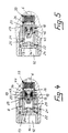
- the residual pressure valve 8 is drawn in the "closed position". In this "closed position" there is no pressure either in the cavity 12 or in the transverse channel 6. Due to the appropriate spring dimensioning with regard to the desired residual pressure of 2.5 bar, the sealing seat 40 is pressed against the sealing body 31 by the plate spring assembly 39 and, on the other hand, the sealing body carrier 18 is kept floating in the web section 16 by the helical compression spring 21 so that the residual pressure valve 8 is closed is, however, the sealing body carrier 18 does not abut the annular projection 42 of the sealing seat carrier 36 nor on the peripheral shoulder 43 of the valve housing 4 nor on the other end face 46 of the web section 16.
- the pressure piece 22 together with the spacer sleeve 25, the sealing body carrier 18 and the sealing seat carrier 36 against the restoring force of the helical compression spring 21 and the plate spring assembly 39 in the direction of the gas channel is caused by this filling pressure 5 shifted in the gas cylinder valve 1 ( Figure 4). This shift continues until the end faces 34 of the guide webs 19 come to rest on the shoulder 43 of the transverse channel 6.
- the compressed gas can now pass through the cavity 12, the opening 14 in the base 13, the bore 24 in the pressure piece 22, the spacer sleeve 25, the passage gaps 29 on the circumferential side of the spacer fingers 27 and the gap 44 between the sealing body carrier 18 and Seal seat carrier 36 in the transverse channel 6 and from there with the open gas cylinder valve 1 into the compressed gas container.
Landscapes
- Engineering & Computer Science (AREA)
- General Engineering & Computer Science (AREA)
- Mechanical Engineering (AREA)
- Filling Or Discharging Of Gas Storage Vessels (AREA)
Claims (8)
- Vanne de pression résiduelle pour un robinet de bouteille à gaz (1) affectée à un réservoir de gaz sous pression, qui présente dans un canal transversal (6) du logement de vanne (4) un corps d'étanchéité (31) fixé sur un support de corps d'étanchéité (18), pouvant venir s'appliquer sous l'influence d'un ressort de compression (21) contre un siège d'étanchéité (40) supporté élastiquement en tant que composant d'un support de siège d'étanchéité (36), qui est encastré centralement dans le côté frontal dirigé vers le siège d'étanchéité (40) du support de corps d'étanchéité (18) et le support de siège d'étanchéité annulaire (36) se situe sur le côté frontal du support de corps d'étanchéité (18), le support de corps d'étanchéité (18) et le support de siège d'étanchéité (36) pouvant au moins être décalés axialement et conjointement par section pour le remplissage du réservoir de gaz sous pression dans le canal transversal (6), caractérisée en ce que le support de corps d'étanchéité (18) est muni sur la périphérie de plusieurs ailettes de guidage (19) coulissant longitudinalement, dans une section d'ailettes (16) du canal transversal (6), le support de siège d'étanchéité (36) s'appuyant sur des doigts d'espacement (27) disposés entre les ailettes de guidage (19) sur la périphérie du support de corps d'étanchéité (18) et à une distance radiale par rapport à la paroi de la section d'ailettes (16) sur une douille d'espacement (25) perforée dans le fond et renfermant sous forme de pot le ressort de compression (21), douille d'espacement qui est intégrée entre le support de corps d'étanchéité (18) et le fond (13) muni d'une ouverture (4) d'une section de douille (15) du canal transversal (6) avec possibilité de coulissement axial.
- Vanne de pression résiduelle selon la revendication 1, caractérisée en ce que le corps d'étanchéité (31) est fixé de façon amovible, en particulier au moyen d'une vis (32), dans une dépression (30) frontale du support de corps d'étanchéité (18).
- Vanne de pression résiduelle selon la revendication 1 ou 2, caractérisée en ce que la face d'étanchéité (33) du corps d'étanchéité (31) fait saillie par rapport aux côtés frontaux (34) des ailettes de guidage (19).
- Vanne de pression résiduelle selon la revendication 1, caractérisée en ce que le siège d'étanchéité annulaire (40) est prévu frontalement par rapport au support de siège d'étanchéité (36).
- Vanne de pression résiduelle selon l'une des revendications 1 à 4, caractérisée en ce que le support de siège d'étanchéité (36) muni périphériquement d'une étanchéité annulaire (37) est encastré dans une section de siège d'étanchéité (35) du canal transversal (6) et se trouve sollicité par un ensemble de ressort à disque (39) dans la direction du support de corps d'étanchéité (18).
- Vanne de pression résiduelle selon la revendication 1, caractérisée en ce que le fond de la gaine d'espacement (25) est conçu sous forme d'élément de compression (22) amovible.
- Vanne de pression résiduelle selon l'une des revendications 1 à 6, caractérisée en ce que le support de corps d'étanchéité (18) et le fond (22) de la gaine d'espacement (25) sont munis de centrages (20, 23) en regard l'un de l'autre pour le ressort de compression (21).
- Vanne de pression résiduelle selon l'une des revendications 1 à 7, caractérisée en ce que le support de corps d'étanchéité (18) et la douille d'espacement (25) sont intégrés dans une cartouche de vanne (9) qui se visse dans le logement de vanne (4).
Applications Claiming Priority (2)
| Application Number | Priority Date | Filing Date | Title |
|---|---|---|---|
| DE4239717 | 1992-11-26 | ||
| DE4239717A DE4239717C1 (de) | 1992-11-26 | 1992-11-26 | Restdruckventil |
Publications (2)
| Publication Number | Publication Date |
|---|---|
| EP0599080A1 EP0599080A1 (fr) | 1994-06-01 |
| EP0599080B1 true EP0599080B1 (fr) | 1997-03-26 |
Family
ID=6473676
Family Applications (1)
| Application Number | Title | Priority Date | Filing Date |
|---|---|---|---|
| EP93117542A Expired - Lifetime EP0599080B1 (fr) | 1992-11-26 | 1993-10-29 | Soupape de pression résiduelle |
Country Status (2)
| Country | Link |
|---|---|
| EP (1) | EP0599080B1 (fr) |
| DE (2) | DE4239717C1 (fr) |
Families Citing this family (2)
| Publication number | Priority date | Publication date | Assignee | Title |
|---|---|---|---|---|
| DE9418833U1 (de) * | 1994-11-24 | 1995-02-16 | Pieper, Günther, 58849 Herscheid | Ventilanordnung für einen Druckgasbehälter |
| CN106499866B (zh) * | 2017-01-09 | 2018-10-12 | 盐城市大冈石油工具厂有限责任公司 | 安全泄压装置 |
Family Cites Families (7)
| Publication number | Priority date | Publication date | Assignee | Title |
|---|---|---|---|---|
| DD76816A (fr) * | ||||
| GB659079A (en) * | 1948-05-06 | 1951-10-17 | Electro Hydraulics Ltd | Improvements in or relating to relief valves |
| US3441050A (en) * | 1966-07-13 | 1969-04-29 | Itt | Pressure equalizing valve |
| US3729019A (en) * | 1971-03-10 | 1973-04-24 | Marvel Eng Co | Bi-directional check valve |
| DE2131805A1 (de) * | 1971-06-26 | 1972-12-28 | Messer Griesheim Gmbh | Ventilsystem |
| JPS4881122A (fr) * | 1972-01-31 | 1973-10-30 | ||
| SE411793B (sv) * | 1978-05-31 | 1980-02-04 | Aga Ab | Anordning avsedd att forhindra temning av ett tryckmediumsystem under ett visst instellt resttryck och att mojliggora fyllning eller vakuumpumpning av systemet |
-
1992
- 1992-11-26 DE DE4239717A patent/DE4239717C1/de not_active Expired - Fee Related
-
1993
- 1993-10-29 EP EP93117542A patent/EP0599080B1/fr not_active Expired - Lifetime
- 1993-10-29 DE DE59305950T patent/DE59305950D1/de not_active Expired - Fee Related
Also Published As
| Publication number | Publication date |
|---|---|
| DE59305950D1 (de) | 1997-04-30 |
| EP0599080A1 (fr) | 1994-06-01 |
| DE4239717C1 (de) | 1994-01-05 |
Similar Documents
| Publication | Publication Date | Title |
|---|---|---|
| DE3107775C2 (fr) | ||
| EP3366958B1 (fr) | Tête de vanne | |
| EP3493917B1 (fr) | Pompe de pulvérisation à doigt | |
| DE29723903U1 (de) | Vorrichtung zum Aufbringen eines Etiketts auf eine Compactdisc oder dergleichen | |
| WO1992014085A1 (fr) | Soupape a cartouche | |
| EP0217013B1 (fr) | Ressort à gaz réglable en longueur | |
| EP0335121A1 (fr) | Poussoir de soupape à réglage hydraulique automatique | |
| DE102005030820B3 (de) | Spannvorrichtung | |
| EP0550503A1 (fr) | Reservoir sous pression a jeter, servant en particulier de recharge pour les installations frigorifiques et les installations de climatisation. | |
| DE3831554C2 (de) | Drosselrückschlagventil | |
| EP1525144A1 (fr) | Valve de regulation de pression | |
| EP0447675B1 (fr) | Ressort à gaz à longueur réglable | |
| DE2141626C3 (de) | Ventilvorrichtung für Aerosolbehälter | |
| EP0901452A1 (fr) | Ampoule a chambres multiples pour liquides sous forme dosee | |
| DE3324608A1 (de) | Kraftstoff-einspritzduese | |
| DE3713023C2 (de) | Vorrichtung zum Spannen von Paletten | |
| WO2022063513A1 (fr) | Dispositif de soupape pour le passage régulé d'un fluide en particulier dans la plage de haute pression | |
| EP0528265A1 (fr) | Applicateur à bille | |
| EP0599080A1 (fr) | Soupape de pression résiduelle | |
| DE2236068A1 (de) | Ventil fuer druckgaspackungen | |
| DE3446407A1 (de) | Justierbare gasfeder | |
| DE3016543A1 (de) | Kraftstoffeinspritzanlage | |
| DE3015873A1 (de) | Automatisches zeitsteuerventil zur wasserabgabesteuerung in bewaesserungsanlagen | |
| EP2994674B1 (fr) | Vanne | |
| DE202006014780U1 (de) | Ventil |
Legal Events
| Date | Code | Title | Description |
|---|---|---|---|
| PUAI | Public reference made under article 153(3) epc to a published international application that has entered the european phase |
Free format text: ORIGINAL CODE: 0009012 |
|
| AK | Designated contracting states |
Kind code of ref document: A1 Designated state(s): BE CH DE DK FR GB IT LI LU NL SE |
|
| 17P | Request for examination filed |
Effective date: 19941108 |
|
| 17Q | First examination report despatched |
Effective date: 19960212 |
|
| GRAG | Despatch of communication of intention to grant |
Free format text: ORIGINAL CODE: EPIDOS AGRA |
|
| GRAH | Despatch of communication of intention to grant a patent |
Free format text: ORIGINAL CODE: EPIDOS IGRA |
|
| GRAH | Despatch of communication of intention to grant a patent |
Free format text: ORIGINAL CODE: EPIDOS IGRA |
|
| GRAA | (expected) grant |
Free format text: ORIGINAL CODE: 0009210 |
|
| AK | Designated contracting states |
Kind code of ref document: B1 Designated state(s): BE CH DE DK FR GB IT LI LU NL SE |
|
| PG25 | Lapsed in a contracting state [announced via postgrant information from national office to epo] |
Ref country code: NL Free format text: LAPSE BECAUSE OF FAILURE TO SUBMIT A TRANSLATION OF THE DESCRIPTION OR TO PAY THE FEE WITHIN THE PRESCRIBED TIME-LIMIT Effective date: 19970326 Ref country code: IT Free format text: LAPSE BECAUSE OF FAILURE TO SUBMIT A TRANSLATION OF THE DESCRIPTION OR TO PAY THE FEE WITHIN THE PRE;WARNING: LAPSES OF ITALIAN PATENTS WITH EFFECTIVE DATE BEFORE 2007 MAY HAVE OCCURRED AT ANY TIME BEFORE 2007. THE CORRECT EFFECTIVE DATE MAY BE DIFFERENT FROM THE ONE RECORDED.SCRIBED TIME-LIMIT Effective date: 19970326 Ref country code: GB Effective date: 19970326 Ref country code: FR Effective date: 19970326 Ref country code: DK Effective date: 19970326 |
|
| REG | Reference to a national code |
Ref country code: CH Ref legal event code: EP |
|
| REF | Corresponds to: |
Ref document number: 59305950 Country of ref document: DE Date of ref document: 19970430 |
|
| PG25 | Lapsed in a contracting state [announced via postgrant information from national office to epo] |
Ref country code: SE Effective date: 19970626 |
|
| EN | Fr: translation not filed | ||
| NLV1 | Nl: lapsed or annulled due to failure to fulfill the requirements of art. 29p and 29m of the patents act | ||
| GBV | Gb: ep patent (uk) treated as always having been void in accordance with gb section 77(7)/1977 [no translation filed] |
Effective date: 19970326 |
|
| PG25 | Lapsed in a contracting state [announced via postgrant information from national office to epo] |
Ref country code: LU Free format text: LAPSE BECAUSE OF NON-PAYMENT OF DUE FEES Effective date: 19971029 |
|
| PG25 | Lapsed in a contracting state [announced via postgrant information from national office to epo] |
Ref country code: LI Free format text: LAPSE BECAUSE OF NON-PAYMENT OF DUE FEES Effective date: 19971031 Ref country code: CH Free format text: LAPSE BECAUSE OF NON-PAYMENT OF DUE FEES Effective date: 19971031 Ref country code: BE Free format text: LAPSE BECAUSE OF NON-PAYMENT OF DUE FEES Effective date: 19971031 |
|
| PLBE | No opposition filed within time limit |
Free format text: ORIGINAL CODE: 0009261 |
|
| STAA | Information on the status of an ep patent application or granted ep patent |
Free format text: STATUS: NO OPPOSITION FILED WITHIN TIME LIMIT |
|
| 26N | No opposition filed | ||
| BERE | Be: lapsed |
Owner name: KM-SCHMOLE G.M.B.H. Effective date: 19971031 |
|
| REG | Reference to a national code |
Ref country code: CH Ref legal event code: PL |
|
| PG25 | Lapsed in a contracting state [announced via postgrant information from national office to epo] |
Ref country code: DE Free format text: LAPSE BECAUSE OF NON-PAYMENT OF DUE FEES Effective date: 19980701 |