EP0599063B1 - Drive unit with an electrical driving motor - Google Patents
Drive unit with an electrical driving motor Download PDFInfo
- Publication number
- EP0599063B1 EP0599063B1 EP93117139A EP93117139A EP0599063B1 EP 0599063 B1 EP0599063 B1 EP 0599063B1 EP 93117139 A EP93117139 A EP 93117139A EP 93117139 A EP93117139 A EP 93117139A EP 0599063 B1 EP0599063 B1 EP 0599063B1
- Authority
- EP
- European Patent Office
- Prior art keywords
- opening
- drive unit
- stop part
- unit according
- stop
- Prior art date
- Legal status (The legal status is an assumption and is not a legal conclusion. Google has not performed a legal analysis and makes no representation as to the accuracy of the status listed.)
- Expired - Lifetime
Links
Images
Classifications
-
- H—ELECTRICITY
- H02—GENERATION; CONVERSION OR DISTRIBUTION OF ELECTRIC POWER
- H02K—DYNAMO-ELECTRIC MACHINES
- H02K7/00—Arrangements for handling mechanical energy structurally associated with dynamo-electric machines, e.g. structural association with mechanical driving motors or auxiliary dynamo-electric machines
- H02K7/08—Structural association with bearings
- H02K7/081—Structural association with bearings specially adapted for worm gear drives
-
- F—MECHANICAL ENGINEERING; LIGHTING; HEATING; WEAPONS; BLASTING
- F16—ENGINEERING ELEMENTS AND UNITS; GENERAL MEASURES FOR PRODUCING AND MAINTAINING EFFECTIVE FUNCTIONING OF MACHINES OR INSTALLATIONS; THERMAL INSULATION IN GENERAL
- F16C—SHAFTS; FLEXIBLE SHAFTS; ELEMENTS OR CRANKSHAFT MECHANISMS; ROTARY BODIES OTHER THAN GEARING ELEMENTS; BEARINGS
- F16C17/00—Sliding-contact bearings for exclusively rotary movement
- F16C17/04—Sliding-contact bearings for exclusively rotary movement for axial load only
- F16C17/08—Sliding-contact bearings for exclusively rotary movement for axial load only for supporting the end face of a shaft or other member, e.g. footstep bearings
-
- F—MECHANICAL ENGINEERING; LIGHTING; HEATING; WEAPONS; BLASTING
- F16—ENGINEERING ELEMENTS AND UNITS; GENERAL MEASURES FOR PRODUCING AND MAINTAINING EFFECTIVE FUNCTIONING OF MACHINES OR INSTALLATIONS; THERMAL INSULATION IN GENERAL
- F16C—SHAFTS; FLEXIBLE SHAFTS; ELEMENTS OR CRANKSHAFT MECHANISMS; ROTARY BODIES OTHER THAN GEARING ELEMENTS; BEARINGS
- F16C2380/00—Electrical apparatus
- F16C2380/26—Dynamo-electric machines or combinations therewith, e.g. electro-motors and generators
- F16C2380/27—Motor coupled with a gear, e.g. worm gears
-
- F—MECHANICAL ENGINEERING; LIGHTING; HEATING; WEAPONS; BLASTING
- F16—ENGINEERING ELEMENTS AND UNITS; GENERAL MEASURES FOR PRODUCING AND MAINTAINING EFFECTIVE FUNCTIONING OF MACHINES OR INSTALLATIONS; THERMAL INSULATION IN GENERAL
- F16H—GEARING
- F16H57/00—General details of gearing
- F16H57/02—Gearboxes; Mounting gearing therein
- F16H57/021—Shaft support structures, e.g. partition walls, bearing eyes, casing walls or covers with bearings
- F16H2057/0213—Support of worm gear shafts
-
- H—ELECTRICITY
- H02—GENERATION; CONVERSION OR DISTRIBUTION OF ELECTRIC POWER
- H02K—DYNAMO-ELECTRIC MACHINES
- H02K2205/00—Specific aspects not provided for in the other groups of this subclass relating to casings, enclosures, supports
- H02K2205/03—Machines characterised by thrust bearings
-
- H—ELECTRICITY
- H02—GENERATION; CONVERSION OR DISTRIBUTION OF ELECTRIC POWER
- H02K—DYNAMO-ELECTRIC MACHINES
- H02K2213/00—Specific aspects, not otherwise provided for and not covered by codes H02K2201/00 - H02K2211/00
- H02K2213/09—Machines characterised by the presence of elements which are subject to variation, e.g. adjustable bearings, reconfigurable windings, variable pitch ventilators
Description
Die Erfindung geht aus von einem Antriebsaggregat nach der Gattung des Hauptanspruchs. Bei derartigen Antriebsaggregaten bewirkt das Schneckengetriebe einen erheblichen Axialschub der Schneckenwelle, der je nach Drehrichtung des Antriebsmotors bzw. der Schneckenwelle voll gegen eine als Anschlag wirkende, durch das Gehäuse hindurchgeschraubte Stellschraube wirkt. Eine ungenügende Sicherung der Stellschraube hat zur Folge, daß dann durch die Schneckenwelle die Schraube so verstellt werden kann, daß die Welle entweder axiales Spiel erhält, oder daß die Stellschraube gegen die eine, ihr zugewandte Stirnseite der Welle gedreht wird, was zu einem Festlaufen der Schneckenwelle und zum Blockieren des Antriebsmotors führt.The invention is based on a drive unit according to the preamble of the main claim. In drive units of this type, the worm gear causes a considerable axial thrust of the worm shaft which, depending on the direction of rotation of the drive motor or the worm shaft, acts fully against an adjusting screw which acts as a stop and is screwed through the housing. Inadequate securing of the set screw has the result that the screw can then be adjusted by the worm shaft so that the shaft either receives axial play, or that the set screw is turned against one end of the shaft facing it, causing the shaft to seize Worm shaft and blocking the drive motor.
Aus der US-PS 5 144 738 ist ein Antriebsaggregat bekannt, bei dem als Anschlag ein mit einem Konus versehener Puffer eingesetzt ist, der mittels einer Blechscheibe arretiert wird.From US-PS 5 144 738 a drive unit is known in which a buffer provided with a cone is used as a stop, which is locked by means of a sheet metal disk.
Es ist ferner ein Antriebsaggregat bekannt, bei dem die Verdrehsicherung der Schneckenwelle durch Verstemmen der Gewindebohrung in dem Metallgehäuse erreicht wird. Eine derartige Arretierung ist zwar kostengünstig, doch ist sie nicht praktikabel, wenn das Gehäuse aus einem spröden Werkstoff oder auch aus Kunststoff besteht. Auch ein Verkleben der Stellschraube in der Gewindebohrung kann keine dauerhafte Verdrehsicherung der Stellschraube gewährleisten, weil die Kleber nicht sicher auf der Kunststoffoberfläche haften und/oder mit der Zeit altern, so daß ein Verdrehen der Verstellschraube und die damit verbundenen Nachteile nicht ausgeschlossen werden können.A drive unit is also known in which the screw shaft is prevented from rotating by caulking the threaded hole in the metal housing. Such a lock is inexpensive, but it is not practical if the housing is made of a brittle material or also consists of plastic. Even sticking the set screw in the threaded hole can not ensure permanent locking of the set screw, because the Adhesives do not adhere securely to the plastic surface and / or age over time, so that twisting of the adjustment screw and the associated disadvantages cannot be ruled out.
Das erfindungsgemäße Antriebsaggregat mit den kennzeichnenden Merkmalen des Hauptanspruchs hat demgegenüber den Vorteil, daß so eine einfache und wirksame Axialspielbegrenzung geschaffen ist, die auf lange Zeit einen problemlosen Betrieb des Antriebsaggregats sicherstellt.The drive unit according to the invention with the characterizing features of the main claim has the advantage that a simple and effective axial play limitation is created, which ensures problem-free operation of the drive unit for a long time.
Durch die in den Unteransprüchen aufgeführten Maßnahmen sind vorteilhafte Weiterbildungen und Verbesserungen des im Hauptanspruch angegebenen Antriebsaggregat möglich.The measures listed in the subclaims enable advantageous developments and improvements of the drive unit specified in the main claim.
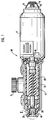
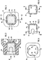
Ein Ausführungsbeispiel der Erfindung ist in der Zeichnung dargestellt und in der nachfolgenden Beschreibung näher erläutert. Es zeigen Figur 1 eine Ansicht eines Antriebsaggregats, teilweise geschnitten, Figur 2 eine Einzelheit bei II in Figur 1, in vergrößerter Darstellung, Figur 3 eine Teil-Draufsicht auf das Antriebsaggregat gemäß Figur 1 in Richtung des Pfeiles III in Figur 2 gesehen, Figur 4 die Draufsicht gemäß Figur 3, wobei das Anschlagteil aus dem Gehäuse entfernt ist, Figur 5 einen Längsschnitt durch das Anschlagteil entlang der Linie V-V in Figur 6 und Figur 6 einen Schnitt durch das Anschlagteil entlang der Linie VI-VI in Figur 5.An embodiment of the invention is shown in the drawing and explained in more detail in the following description. 1 shows a view of a drive unit, partially in section, FIG. 2 shows a detail at II in FIG. 1, in an enlarged view, FIG. 3 shows a partial top view of the drive unit according to FIG. 1 in the direction of arrow III in FIG. 2, FIG. 4 3, the stop part being removed from the housing, FIG. 5 a longitudinal section through the stop part along the line VV in FIG. 6 and FIG. 6 a section through the stop part along the line VI-VI in FIG. 5.
Ein in Figur 1 dargestelltes Antriebsaggregat 10 weist einen elektrischen Antriebsmotor 11 auf, dem ein Schneckengetriebe 12 nachgeordnet ist. Das Schneckengetriebe 12 hat ein Abtriebsritzel 14, durch welches das Antriebsaggregat 10 beispielsweise mit dem Antriebsmechanismus eines Kraftfahrzeug-Schiebedachs oder dergleichen verbunden werden kann. Das Schneckengetriebe 12 ist in einem Gehäuse 16 untergebracht, das fest mit einem zum Antriebsmotor 11 gehörenden Gehäuses 17 verbunden ist und mit diesem zusammen ein Aggregat-Gehäuse bildet, welches den Antriebsmotor 10 und das Schneckengetriebe 12 vollständig umschließt. Beim Ausführungsbeispiel hat die zum Schneckengetriebe 12 gehörende Schneckenwelle 20 eine Verlängerung 18, welche die Ankerwelle des Antriebsmotors 11 bildet. Da die Ankerwelle 18 und die Schneckenwelle 20 eine Baueinheit bilden, gilt alles was im folgenden zur Schneckenwelle 20 gesagt wird sinngemäß auch für die Ankerwelle 18 des Antriebsmotors 11. Es ist einleuchtend, daß es in der Praxis gleichgültig ist, ob eine Längsspiel-Anschlagssicherung an der freien Stirnfläche der Schneckenwelle 20 oder an der freien Stirnfläche der Ankerwelle 18 angebracht wird. In beiden Fällen wird die als Baueinheit anzusehende Welle, bestehend aus Ankerwelle 18 und Schneckenwelle 20 in Achsrichtung spielfrei eingestellt.A
Wie Figur 1 zeigt, weist das zu Motor 11 gehörende Gehäuseteil 17 des Aggregatgehäuses 16, 17 einen Anschlag 19 auf, der an diesem festgehalten ist. In Verlängerung der Schneckenwelle 20 gesehen, hat das Getriebegehäuse 16 auf der vom Anschlag 19 abgewandten Seite einen Durchbruch 24, in dem ein im wesentlichen topfförmiges Anschlagteil 26 angeordnet ist. Die Anordnung dieses Anschlagteils 26 ist dabei so getroffen, daß es mit der Außenseite 28 des Topfbodens 30 an der Endfläche 32 der Schneckenwelle 20 anliegt.As FIG. 1 shows, the housing part 17 of the
Wie insbesondere die Figuren 3, 5 und 6 zeigen, hat das Anschlagteil 26, bezogen auf die Topflängsachse, einen von der Kreisform abweichenden Querschnitt. Diese Querschnittsform ist beim Ausführungsbeispiel im wesentlichen quadratisch. Der Querschnittsform des Anschlagteils 26 ist die Form des Durchbruchs 24 angepaßt. Dadurch wird auf einfache Weise eine Verdrehsicherung des Anschlagteils 26 im Durchbruch 24 sichergestellt. Diese auf die Querschnittsform des Anschlagteils 26 angepaßte Form des Durchbruchs 24 erstreckt sich von der Innenseite des Gehäuses aus, d. h. also von der Schneckenwelle 20 aus nur über einen Teilbereich des Gehäuses 16. Der Durchbruch 24 ist von der Außenseite des Gehäuses 16 her über einen Teilabschnitt im Querschnitt größer als der innere, der Querschnittsform des Anschlagteil 26 angepaßte Abschnitt des Durchbruchs 24. Beim Ausführungsbeispiel ist die innere, auf die Querschnittsform des Anschlagteils 6 und 20 abgestimmte Querschnittsform mit der Bezugszahl 34 versehen worden (Figur 4). Der äußere Abschnitt des Durchbruchs 34 ist in Figur 4 mit 36 bezeichnet. Dieser äußere Bereich hat die Form eines Umkreises in dem die quadratische Querschnittsform des Anschlagteils 26 liegt. An den den Seitenflächen des Anschlagteils 26 benachbarten Bereichen hat dieser Umkreis Vorsprünge 38 welche bis nahe an die Seitenkanten des quadratischen Durchbruchsbereichs heranführen (Figuren 3 und 4). Weiter zeigen diese Figuren, daß sich in diesen Vorsprüngen 38 Rillen befinden (durch die gestrichelten Linien angedeutet), welche beispielsweise durch die Anordnung eines Gewindes gebildet sein können. Schließlich zeigen die Figuren 5 und 6, daß in den Topfwänden 40 des Anschlagteils 26 zum Topfrand 42 offene, schlitzartige Ausnehmungen 44 angeordnet sind.As particularly shown in FIGS. 3, 5 and 6, the
Bei der Montage des Antriebsaggregats 10 ist dafür zu sorgen, daß die Welle 18, 20 ordnungsgemäß am Anschlag 19 zur Anlage kommt. Um eine axialspielfreie Montage dieser Welle 16, 18 zu erreichen, wird nun das topfförmige Anschlagteil 26 in den Durchbruch 24 eingesetzt, bis die Außenseite 28 des Topfbodens 30 an der Endfläche 32 der Schneckenwelle 20 spielfrei anliegt. Danach wird, vorzugsweise bei aufgestellten Aggregat 10, in den Durchbruch 24 eine Vergußmasse, vorzugsweise ein bei UV-Licht rasch aushärtender Metallkleber, eingefüllt, der von der Topfform des Anschlagteils 26 aus über die Ausnehmungen 44 in die Bereiche des Durchbruchs 24 übertritt, wo der Querschnitt des Durchbruchs 24 größer ist als der Querschnitt des Anschlagteils 26, dadurch gelangt die Vergußmasse auch in die Rillen der Vorsprünge 38, so daß eine hervorragende Axialsicherung des Anschlagteils 26 erreicht ist.When assembling the
Claims (8)
- Drive unit with an electric drive motor (11) and a worm gear (12) which is effectively connected to the said drive motor (11) and is arranged downstream thereof and whose worm shaft (20) preferably has an extension which forms the armature shaft (18) of the motor (11) and the worm shaft (20) is held without longitudinal play between two stops (19, 26) facing its end faces, the one stop (19) being permanently arranged on a housing (16, 17) which surrounds the unit (10), and the housing (16, 17) having, viewed in the extension of the worm shaft (18, 20), an opening (24) on the side facing away from the one stop (19), into which opening (24) a stop part (26) which has a stop shoulder (28) is inserted, characterized in that the stop part (26) is provided on its side facing away from the stop shoulder with at least one cut-out (44) which, filled with a casting compound, provides positional securing of the stop part (26) in the opening (24).
- Drive unit according to Claim 1, characterized in that the stop part (26) is of essentially pot-shaped construction and is inserted with the outside (28) of the base (30) of the pot facing the other end face (32) of the worm shaft (18, 20) and is attached in the opening (24) by means of the casting compound (46).
- Drive unit according to Claim 2, characterized in that, in relation to the longitudinal axis of the pot, the stop part (26) has a cross-section which deviates from the circular shape, and in that the shape of the opening (24) in the housing is matched to this cross-sectional shape.
- Drive unit according to one of Claims 2 or 3, characterized in that the pot wall (40) of the stop part (26) has at least one recess (44) which is open with respect to the edge (42) of the pot.
- Drive unit according to one of Claims 3 or 4, characterized in that the opening (24), viewed from the outside of the housing (16), has a cross-section which is greater than the inner section of the opening (24) which guides the stop part (26).
- Drive unit according to Claim 5, characterized in that the outer section (36) of the opening (24) is provided with grooves on its wall.
- Drive unit according to one of Claims 3 to 6, characterized in that the cross-sectional shapes of the stop part (26) and of that section of the opening in the housing (16) which guides the stop part are essentially square.
- Drive unit according to one of Claims 1 to 7, characterized in that the casting compound is a metal bonding agent which cures quickly in ultraviolet light.
Applications Claiming Priority (2)
| Application Number | Priority Date | Filing Date | Title |
|---|---|---|---|
| DE4239934A DE4239934A1 (en) | 1992-11-27 | 1992-11-27 | Drive unit with an electric drive motor |
| DE4239934 | 1992-11-27 |
Publications (2)
| Publication Number | Publication Date |
|---|---|
| EP0599063A1 EP0599063A1 (en) | 1994-06-01 |
| EP0599063B1 true EP0599063B1 (en) | 1997-03-05 |
Family
ID=6473821
Family Applications (1)
| Application Number | Title | Priority Date | Filing Date |
|---|---|---|---|
| EP93117139A Expired - Lifetime EP0599063B1 (en) | 1992-11-27 | 1993-10-22 | Drive unit with an electrical driving motor |
Country Status (3)
| Country | Link |
|---|---|
| EP (1) | EP0599063B1 (en) |
| DE (2) | DE4239934A1 (en) |
| ES (1) | ES2098623T3 (en) |
Families Citing this family (10)
| Publication number | Priority date | Publication date | Assignee | Title |
|---|---|---|---|---|
| DE29513699U1 (en) * | 1995-08-25 | 1996-09-26 | Siemens Ag | Arrangement for adjusting the axial play of a slide-bearing shaft of a small motor drive |
| FR2771469B1 (en) * | 1997-11-27 | 2000-02-04 | Meritor Light Vehicle Sys Ltd | GEAR MOTOR FOR DRIVING VEHICLE EQUIPMENT SUCH AS A WINDOW REGULATOR WITH REMOVAL OF THE AXIAL CLEARANCE OF ITS SHAFT LINE |
| DE10117573A1 (en) * | 2001-04-07 | 2002-10-10 | Valeo Auto Electric Gmbh | Bearing arrangement and electric drive with such a bearing arrangement |
| DE10311788A1 (en) * | 2003-03-18 | 2004-09-30 | Valeo Wischersysteme Gmbh | Shaft fixing method for preventing play of shaft in electric motors for use in vehicles, involves pushing bearing bush further into opening of cap until bearing bush finds its target position when cap is fastened to gear box |
| DE10317128A1 (en) * | 2003-04-14 | 2004-10-28 | BSH Bosch und Siemens Hausgeräte GmbH | Electrical machine and assembly method therefor |
| DE102006021986A1 (en) * | 2006-05-11 | 2007-11-15 | Robert Bosch Gmbh | Drive unit with a thrust washer and method for producing such |
| DE102010043974A1 (en) * | 2010-11-16 | 2012-05-16 | Robert Bosch Gmbh | Gear drive unit |
| FR2977283B1 (en) * | 2011-06-28 | 2013-08-30 | Valeo Systemes Dessuyage | PERMANENT FASTENING SCREW |
| DE102014226001A1 (en) * | 2014-12-16 | 2016-06-16 | Robert Bosch Gmbh | Transmission drive device and method for producing a transmission drive device |
| CN104986019B (en) * | 2015-07-29 | 2017-07-18 | 席智武 | A kind of switch for being used to control vehicle dormer window |
Family Cites Families (3)
| Publication number | Priority date | Publication date | Assignee | Title |
|---|---|---|---|---|
| US2976088A (en) * | 1958-12-15 | 1961-03-21 | Gen Motors Corp | End play device for dynamoelectric machine |
| EP0394512A1 (en) * | 1989-04-25 | 1990-10-31 | Siemens Aktiengesellschaft | Device for limiting the axial clearance of the shaft of a motor drive |
| US5144738A (en) * | 1991-04-29 | 1992-09-08 | Ford Motor Company | Automatic retention adjustment of motor armature assembly |
-
1992
- 1992-11-27 DE DE4239934A patent/DE4239934A1/en not_active Withdrawn
-
1993
- 1993-10-22 ES ES93117139T patent/ES2098623T3/en not_active Expired - Lifetime
- 1993-10-22 EP EP93117139A patent/EP0599063B1/en not_active Expired - Lifetime
- 1993-10-22 DE DE59305602T patent/DE59305602D1/en not_active Expired - Fee Related
Also Published As
| Publication number | Publication date |
|---|---|
| DE4239934A1 (en) | 1994-06-01 |
| DE59305602D1 (en) | 1997-04-10 |
| ES2098623T3 (en) | 1997-05-01 |
| EP0599063A1 (en) | 1994-06-01 |
Similar Documents
| Publication | Publication Date | Title |
|---|---|---|
| DE3610284C2 (en) | ||
| EP0599063B1 (en) | Drive unit with an electrical driving motor | |
| DE102009043322A1 (en) | Electromotive auxiliary drive | |
| EP0655358A1 (en) | Apparatus for adjusting piece parts of a vehicle between two end positions | |
| EP2491257B1 (en) | Joining means for components and furniture | |
| DE3744274C2 (en) | Electric motor, especially small electric motor | |
| DE102005040646A1 (en) | Electric motor accessory drive system e.g. windscreen wiper drive system, for e.g. road vehicle, has magnetic sensors acting together with ring magnet for determining angle position of rotary motion of shaft of drive | |
| DE1255275B (en) | Spacer for reinforced concrete reinforcement bars | |
| DE3423315C2 (en) | ||
| DE3609366C2 (en) | ||
| DE4128110A1 (en) | Electromotor with triple bearings on armature shaft - is supported in colinear cylindrical bearings with provision for self-alignment at end remote from gearing | |
| EP0913609B1 (en) | Valve | |
| DE10258036A1 (en) | Electric motor, in particular for a windshield wiper device and windshield wiper device, in particular for a motor vehicle | |
| DE4139670A1 (en) | Valve with electromagnetically operated valve seat seal - has valve seat on nozzle adjustable in two part valve body having base supporting magnetic head and nozzle | |
| EP1897206B1 (en) | Bearing arrangement | |
| DE19623405C2 (en) | Support for holding a closure element | |
| DE8603917U1 (en) | Check valve with a two-part or multi-part housing for medical purposes | |
| DE3804219C2 (en) | Actuator | |
| DE10047633C2 (en) | Clamp bracket for a sun and / or privacy protection device | |
| DE10343168A1 (en) | Electric motor drive for wiper device for vehicle has counter stop provided on external surface of housing part and lock element independent of functional elements of external lever transmission | |
| DE4130079A1 (en) | Installation appts. for ancillary equipment in road vehicles, e.g. seat adjusters - has drive motor coupled to mechanism via double worm and pinion transmission supported on single frame to resist loads | |
| DE10262404B3 (en) | Electric motor, in particular for a windscreen wiper device and windscreen wiper device, in particular for a motor vehicle | |
| DE2352535C3 (en) | Drive unit for wiping devices on motor vehicles | |
| DE102010002159A1 (en) | Drive unit connecting device for adjusting device of electro-motorized adjustable component of motor vehicle seat, has coupling element arranged with strength structure of motor vehicle seat at interface of connection of drive unit | |
| DE2925032A1 (en) | Drive unit for adjusting vehicle seat - has motor shaft adjusted axially by socket with end-stop acting on shaft end |
Legal Events
| Date | Code | Title | Description |
|---|---|---|---|
| PUAI | Public reference made under article 153(3) epc to a published international application that has entered the european phase |
Free format text: ORIGINAL CODE: 0009012 |
|
| AK | Designated contracting states |
Kind code of ref document: A1 Designated state(s): DE ES FR IT |
|
| 17P | Request for examination filed |
Effective date: 19941201 |
|
| 17Q | First examination report despatched |
Effective date: 19950901 |
|
| GRAG | Despatch of communication of intention to grant |
Free format text: ORIGINAL CODE: EPIDOS AGRA |
|
| GRAH | Despatch of communication of intention to grant a patent |
Free format text: ORIGINAL CODE: EPIDOS IGRA |
|
| GRAH | Despatch of communication of intention to grant a patent |
Free format text: ORIGINAL CODE: EPIDOS IGRA |
|
| GRAA | (expected) grant |
Free format text: ORIGINAL CODE: 0009210 |
|
| AK | Designated contracting states |
Kind code of ref document: B1 Designated state(s): DE ES FR IT |
|
| ET | Fr: translation filed | ||
| REF | Corresponds to: |
Ref document number: 59305602 Country of ref document: DE Date of ref document: 19970410 |
|
| ET | Fr: translation filed |
Free format text: CORRECTIONS |
|
| REG | Reference to a national code |
Ref country code: ES Ref legal event code: FG2A Ref document number: 2098623 Country of ref document: ES Kind code of ref document: T3 |
|
| ITF | It: translation for a ep patent filed |
Owner name: STUDIO JAUMANN |
|
| PGFP | Annual fee paid to national office [announced via postgrant information from national office to epo] |
Ref country code: FR Payment date: 19971027 Year of fee payment: 5 |
|
| PGFP | Annual fee paid to national office [announced via postgrant information from national office to epo] |
Ref country code: ES Payment date: 19971031 Year of fee payment: 5 |
|
| PLBE | No opposition filed within time limit |
Free format text: ORIGINAL CODE: 0009261 |
|
| STAA | Information on the status of an ep patent application or granted ep patent |
Free format text: STATUS: NO OPPOSITION FILED WITHIN TIME LIMIT |
|
| 26N | No opposition filed | ||
| PG25 | Lapsed in a contracting state [announced via postgrant information from national office to epo] |
Ref country code: ES Free format text: LAPSE BECAUSE OF NON-PAYMENT OF DUE FEES Effective date: 19981023 |
|
| PG25 | Lapsed in a contracting state [announced via postgrant information from national office to epo] |
Ref country code: FR Free format text: LAPSE BECAUSE OF NON-PAYMENT OF DUE FEES Effective date: 19990630 |
|
| REG | Reference to a national code |
Ref country code: FR Ref legal event code: ST |
|
| PGFP | Annual fee paid to national office [announced via postgrant information from national office to epo] |
Ref country code: DE Payment date: 19991221 Year of fee payment: 7 |
|
| PG25 | Lapsed in a contracting state [announced via postgrant information from national office to epo] |
Ref country code: DE Free format text: LAPSE BECAUSE OF NON-PAYMENT OF DUE FEES Effective date: 20010703 |
|
| REG | Reference to a national code |
Ref country code: ES Ref legal event code: FD2A Effective date: 19991113 |
|
| PG25 | Lapsed in a contracting state [announced via postgrant information from national office to epo] |
Ref country code: IT Free format text: LAPSE BECAUSE OF NON-PAYMENT OF DUE FEES;WARNING: LAPSES OF ITALIAN PATENTS WITH EFFECTIVE DATE BEFORE 2007 MAY HAVE OCCURRED AT ANY TIME BEFORE 2007. THE CORRECT EFFECTIVE DATE MAY BE DIFFERENT FROM THE ONE RECORDED. Effective date: 20051022 |