EP0598800B1 - Package and packaging of fibre optic components - Google Patents
Package and packaging of fibre optic components Download PDFInfo
- Publication number
- EP0598800B1 EP0598800B1 EP92917534A EP92917534A EP0598800B1 EP 0598800 B1 EP0598800 B1 EP 0598800B1 EP 92917534 A EP92917534 A EP 92917534A EP 92917534 A EP92917534 A EP 92917534A EP 0598800 B1 EP0598800 B1 EP 0598800B1
- Authority
- EP
- European Patent Office
- Prior art keywords
- inner housing
- sheet
- fibre optic
- housing
- flexible material
- Prior art date
- Legal status (The legal status is an assumption and is not a legal conclusion. Google has not performed a legal analysis and makes no representation as to the accuracy of the status listed.)
- Expired - Lifetime
Links
Images


Classifications
-
- G—PHYSICS
- G02—OPTICS
- G02B—OPTICAL ELEMENTS, SYSTEMS OR APPARATUS
- G02B6/00—Light guides; Structural details of arrangements comprising light guides and other optical elements, e.g. couplings
- G02B6/24—Coupling light guides
- G02B6/26—Optical coupling means
- G02B6/28—Optical coupling means having data bus means, i.e. plural waveguides interconnected and providing an inherently bidirectional system by mixing and splitting signals
- G02B6/2804—Optical coupling means having data bus means, i.e. plural waveguides interconnected and providing an inherently bidirectional system by mixing and splitting signals forming multipart couplers without wavelength selective elements, e.g. "T" couplers, star couplers
- G02B6/2821—Optical coupling means having data bus means, i.e. plural waveguides interconnected and providing an inherently bidirectional system by mixing and splitting signals forming multipart couplers without wavelength selective elements, e.g. "T" couplers, star couplers using lateral coupling between contiguous fibres to split or combine optical signals
- G02B6/2835—Optical coupling means having data bus means, i.e. plural waveguides interconnected and providing an inherently bidirectional system by mixing and splitting signals forming multipart couplers without wavelength selective elements, e.g. "T" couplers, star couplers using lateral coupling between contiguous fibres to split or combine optical signals formed or shaped by thermal treatment, e.g. couplers
-
- G—PHYSICS
- G02—OPTICS
- G02B—OPTICAL ELEMENTS, SYSTEMS OR APPARATUS
- G02B6/00—Light guides; Structural details of arrangements comprising light guides and other optical elements, e.g. couplings
- G02B6/24—Coupling light guides
- G02B6/36—Mechanical coupling means
-
- G—PHYSICS
- G02—OPTICS
- G02B—OPTICAL ELEMENTS, SYSTEMS OR APPARATUS
- G02B6/00—Light guides; Structural details of arrangements comprising light guides and other optical elements, e.g. couplings
- G02B6/24—Coupling light guides
- G02B6/36—Mechanical coupling means
- G02B6/3628—Mechanical coupling means for mounting fibres to supporting carriers
- G02B6/3632—Mechanical coupling means for mounting fibres to supporting carriers characterised by the cross-sectional shape of the mechanical coupling means
- G02B6/3636—Mechanical coupling means for mounting fibres to supporting carriers characterised by the cross-sectional shape of the mechanical coupling means the mechanical coupling means being grooves
Definitions
- This invention relates to the packaging of fibre optic components.
- the invention is described herein with particular reference to the packaging of optical fibre couplers but it will be readily appreciated that the principles of the invention are readily applicable to the packaging of any fibre optic component.
- Optical fibre couplers are presently supplied in a package which is designed both to physically protect the component and to prevent the ingress of moisture and other contaminants to the component.
- the coupler is disposed in an inner cylindrical housing formed of two half silica tubes which are machined to tight dimensional tolerances. These half tubes are brought together and attached together with adhesive.
- the resultant capsule includes respective adhesive deposits which serve to anchor the optical fibre component to the inner surface of the capsule and to seal the ends through which the fibres extend. Additional adhesive may be applied to the ends of the capsule to stabilise the fibres over a wide temperature range.
- the capsule is placed within a stainless steel outer casing which is in turn filled with an elastomer compound. The stainless steel outer casing is provided to give additional strength and protection to the optical component assembly.
- Optical fibre couplers are required to have lifetimes approaching 40 years and to withstand extensive environmental variations. Even though the silica capsule is sealed with adhesive, it has been found through intensive simulated environmental testing that these adhesives are not consistently impervious to moisture over extended periods of time. Test samples have been detected where moisture has ingressed the capsule and affected coupler performance.
- the invention provides a fibre optic component package comprising:
- the invention further provides, in another aspect, a method of packaging a fibre optic component comprising:
- the sheet is preferably a metal foil of any suitably compliant metal, for example tin, nickel, gold, aluminium, monel or an appropriate alloy.
- the foil is advantageously of a thickness in the range 0.01 to 50 micron.
- the foil is preferably wrapped about the inner housing so as to be overlapped longitudinally of the housing.
- the inner housing may be of generally tubular form, e.g. a capsule formed from two half tubes of silica or other appropriate material.
- Adhesive means is preferably provided to maintain the housing and optical fibres as an assembly. Where the inner housing is a tube, this adhesive means preferably includes adhesive deposits to seal the ends of the tube.
- the package may further comprise an outer casing, e.g. a tubular casing, of material such as stainless steel, selected to provide physical protection for the package.
- an outer casing e.g. a tubular casing, of material such as stainless steel, selected to provide physical protection for the package.
- the assembly of the inner housing and the surrounding moisture impervious layer may be retained in the casing in a suitable filling such as silicone elastomer.
- the sealant adhesive is preferably an epoxy compound.
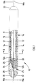
- the illustrated fibre optic component package 10 includes the component itself 11, an inner housing 12 for supporting the component comprising an elongate tubular capsule of silica, a substantially moisture impervious layer 13 including a metal foil wrap 14 providing a sheet of flexible material about housing 12, and an outer casing 16.
- Component 11 may be a fused biconical taper fibre optic coupler and respective pairs of optical fibres 18a, 19a and 18b, 19b then extend from the ends of package 10.
- Inner housing or capsule 12 is formed of two half tubes 12a, 12b of silica glass which are butted at their longitudinal edges and glued along these edges to form a tubular enclosure 17 for the coupler.
- Silica half tube 12b is slightly longer than half tube 12a and respective deposits of adhesive 20 at the ends of half tube 12b locate fibres 18, 19, and therefore coupler 11, centrally of the capsule.
- Adhesive deposits 20 also seal the ends of the capsule and provide additional adhesion between the two halves.
- Capsule 12 is typically formed in a final step on the coupler production machine: the two half tubes, with adhesive along their edges, are brought together about a new coupler and the adhesive deposits 20 applied while the fibres 18, 19 are positioned under tension by adjustable clamp devices. The adhesive is cured before the coupler is removed for further processing.
- Foil wrap 14 is substantially moisture impervious and is typically of thickness about 10 to 30 micron, for example 25 micron, and preferably in the range 0.01 to 50 micron.
- the foil may be formed of any suitably compliant metal, for example tin, nickel, gold, aluminium, monel or an appropriate alloy.
- the foil is circumferentially overlapped at 15 ( Figure 2).
- the overlapped portion is sealed by a suitable sealant such as epoxy which may also serve to bond the foil to the inner housing 12.
- Moisture ingress at the ends of the tubular wrap, defined by edge 25, is resisted by the disposition of sealant epoxy in the region 26.
- the epoxy compound preferably bonds to the foil 14, housing 12 and adhesive deposits 20.
- the package 10 is completed by a filling 28 of a low shear strength silicone elastomer within sleeve 16, according to known practice, and by suitable end caps 30 defining ports 32 for the fibres.
- the metal selected for foil 14 should not have a galvanic action with the material of sleeve 16 as, over extended periods of time, water may then penetrate the sleeve.
- Sleeve 16 may be stainless steel or other suitable material. If sleeve 16 is stainless steel, a suitable material for the foil 14 is tin.
- the capsule 12 might be transported from the coupler production machine and first painted along its exterior cylindrical surfaces with the selected epoxy compound.
- the painted capsule might then be placed in foil 14' folded into a U-section in a groove 42 of a wrapping form 40, with one side of the foil projecting slightly higher than the other.
- Two moving wedges (not shown) would then wrap first the short side and then the long side of the foil onto the painted capsule to complete wrap 14. Excess epoxy compound would be squeezed into the overlap region at the completion of the wrap.
- end fillings 26 might be provided by applying additional epoxy compound to each end of the wrap either before or after completion of folding.
- the selected epoxy compound may be applied to the inner surface of the foil before wrapping.
- the preferred arrangement is that at least a portion of the sealant adhesive is wrapped by the foil and that the sealant adhesive serves to bond the foil 14 and to provide a barrier against moisture ingress to the fibre optic component 11.
- the epoxy compound fills at least those regions at edges of the foil, for example, at the respective axial ends of the wrap and at the region 15 ( Figure 2) where the longitudinal edges overlap.
- the epoxy compound substantially fills the enclosed volume between the foil wrap and housing 12, ie forms a thin layer between the foil wrap and housing 12.
- the package On the completion of wrapping, the package would be removed from the form and placed in an oven for thermal curing of the epoxy compound.
- the wrapped capsule is placed in stainless steel sleeve 16, which is then filled with silicone elastomer in the known manner, and provided with end caps 30.
- the illustrated package arrangement provides a significant improvement in sealing of the inner silica capsule 12 without unacceptably adding to the manufacturing cost of the package, and without significantly increasing its weight. This is achieved without risking problems with thermal coefficient mis-matches: thermal expansion will not be a problem as the metal foil is a very thin metal layer and will be constrained by the much larger mass of the silica capsule.
- the arrangement provides full epoxy/metal protection around the sealed capsule and allows the metal foil to be added to the silica capsule in a wrapping action which avoids the retention of air bubbles, which would not be the case if a metal tube was brought about the capsule.
- water vapour will need to penetrate reasonable lengths of epoxy material 26 before even reaching the innermost housing 12 which in itself is sealed.
- the metal foil wrap 14, and its manner of application, is such that any small holes in the adhesive at the longitudinal butt joins between the half tubes 12a, 12b will be sealed up by the foil and by the added epoxy compound.
- the present applicant has found that, in the long term, such small holes can be the source of moisture breaches.
- the inner housing 12 might not wholly encircle the fibre optic component(s).
Abstract
Description
- This invention relates to the packaging of fibre optic components. The invention is described herein with particular reference to the packaging of optical fibre couplers but it will be readily appreciated that the principles of the invention are readily applicable to the packaging of any fibre optic component.
- Optical fibre couplers are presently supplied in a package which is designed both to physically protect the component and to prevent the ingress of moisture and other contaminants to the component. In one known assembly, the coupler is disposed in an inner cylindrical housing formed of two half silica tubes which are machined to tight dimensional tolerances. These half tubes are brought together and attached together with adhesive. The resultant capsule includes respective adhesive deposits which serve to anchor the optical fibre component to the inner surface of the capsule and to seal the ends through which the fibres extend. Additional adhesive may be applied to the ends of the capsule to stabilise the fibres over a wide temperature range. The capsule is placed within a stainless steel outer casing which is in turn filled with an elastomer compound. The stainless steel outer casing is provided to give additional strength and protection to the optical component assembly.
- Optical fibre couplers are required to have lifetimes approaching 40 years and to withstand extensive environmental variations. Even though the silica capsule is sealed with adhesive, it has been found through intensive simulated environmental testing that these adhesives are not consistently impervious to moisture over extended periods of time. Test samples have been detected where moisture has ingressed the capsule and affected coupler performance.
- It is not possible to provide a hermetic glass-metal seal with the outer metal casing because of a mismatch of thermal expansion coefficients between most metals and silica.
- It is accordingly an object of the invention to provide an arrangement for packaging optical fibre components which provides improved sealing against moisture ingress relative to presently known arrangements but which does not unacceptably increase manufacturing costs.
- In one aspect, the invention provides a fibre optic component package comprising:
- one or more fibre optic components;
- an inner housing supporting the component(s), one or more optical fibres associated with the component(s) extending from the housing; and
- an enclosure for the inner housing, the enclosure comprising:
- i) a layer which is substantially impervious to moisture including water vapour and which encloses said inner housing, said layer including a sheet of substantially moisture impervious flexible material wrapped about the housing; and
- ii) a moisture impervious sealant adhesive which serves to bond said sheet of flexible material and fills at least those regions at edges of said sheet at the axial ends of the wrap and at the region (15) where the longitudinal edges overlap.
- The invention further provides, in another aspect, a method of packaging a fibre optic component comprising:
- supporting the component in an inner housing, with one or more optical fibres associated with the component extending from the housing; and
- enclosing said housing in an enclosure, the enclosure comprising:
- a layer which is substantially impervious to moisture including water vapour, said layer including a sheet of substantially moisture impervious flexible material wrapped about the housing; and
- a substantially moisture impervious sealant adhesive which serves to bond said sheet of flexible material and fills at least those regions at edges of said sheet at the axial ends of the wrap and at the region (15) where the longitudinal edges overlap.
- The sheet is preferably a metal foil of any suitably compliant metal, for example tin, nickel, gold, aluminium, monel or an appropriate alloy. The foil is advantageously of a thickness in the range 0.01 to 50 micron. The foil is preferably wrapped about the inner housing so as to be overlapped longitudinally of the housing.
- In a practical embodiment, the inner housing may be of generally tubular form, e.g. a capsule formed from two half tubes of silica or other appropriate material.
- Adhesive means is preferably provided to maintain the housing and optical fibres as an assembly. Where the inner housing is a tube, this adhesive means preferably includes adhesive deposits to seal the ends of the tube.
- The package may further comprise an outer casing, e.g. a tubular casing, of material such as stainless steel, selected to provide physical protection for the package. The assembly of the inner housing and the surrounding moisture impervious layer may be retained in the casing in a suitable filling such as silicone elastomer.
- The sealant adhesive is preferably an epoxy compound.
- The invention will now be further described, by way of example only, with reference to the accompanying drawings, in which:
- Figure 1 is a side elevation, partially axially sectioned, of a fibre optic component package according to an embodiment of the invention;
- Figure 2 is a cross-section on the line 2-2 in Figure 1;
- Figure 3 is a very schematic representation of an arrangement by which the package of Figure 1 might be formed in accordance with the invention.
- The illustrated fibre
optic component package 10 includes the component itself 11, aninner housing 12 for supporting the component comprising an elongate tubular capsule of silica, a substantially moistureimpervious layer 13 including ametal foil wrap 14 providing a sheet of flexible material abouthousing 12, and anouter casing 16.Component 11 may be a fused biconical taper fibre optic coupler and respective pairs ofoptical fibres package 10. - Inner housing or
capsule 12 is formed of twohalf tubes tubular enclosure 17 for the coupler.Silica half tube 12b is slightly longer thanhalf tube 12a and respective deposits ofadhesive 20 at the ends ofhalf tube 12b locate fibres 18, 19, and therefore coupler 11, centrally of the capsule.Adhesive deposits 20 also seal the ends of the capsule and provide additional adhesion between the two halves. Capsule 12 is typically formed in a final step on the coupler production machine: the two half tubes, with adhesive along their edges, are brought together about a new coupler and theadhesive deposits 20 applied while the fibres 18, 19 are positioned under tension by adjustable clamp devices. The adhesive is cured before the coupler is removed for further processing. - Foil
wrap 14 is substantially moisture impervious and is typically of thickness about 10 to 30 micron, for example 25 micron, and preferably in the range 0.01 to 50 micron. The foil may be formed of any suitably compliant metal, for example tin, nickel, gold, aluminium, monel or an appropriate alloy. The foil is circumferentially overlapped at 15 (Figure 2). The overlapped portion is sealed by a suitable sealant such as epoxy which may also serve to bond the foil to theinner housing 12. Moisture ingress at the ends of the tubular wrap, defined byedge 25, is resisted by the disposition of sealant epoxy in theregion 26. The epoxy compound preferably bonds to thefoil 14, housing 12 andadhesive deposits 20. - The
package 10 is completed by a filling 28 of a low shear strength silicone elastomer withinsleeve 16, according to known practice, and bysuitable end caps 30 definingports 32 for the fibres. - It will be appreciated that the metal selected for
foil 14 should not have a galvanic action with the material ofsleeve 16 as, over extended periods of time, water may then penetrate the sleeve.Sleeve 16 may be stainless steel or other suitable material. Ifsleeve 16 is stainless steel, a suitable material for thefoil 14 is tin. - The manner in which
inner capsule 12 is formed has already been described. According to one method of completing the illustrated package, thecapsule 12 might be transported from the coupler production machine and first painted along its exterior cylindrical surfaces with the selected epoxy compound. With reference to the diagram of Figure 3, the painted capsule might then be placed in foil 14' folded into a U-section in agroove 42 of a wrappingform 40, with one side of the foil projecting slightly higher than the other. Two moving wedges (not shown) would then wrap first the short side and then the long side of the foil onto the painted capsule to completewrap 14. Excess epoxy compound would be squeezed into the overlap region at the completion of the wrap. Excess epoxy compound would also be squeezed from the ends of the wrap during this two-step motion by pressing down theends 34 of the wrap, thus forming and retainingend fillings 26. Alternatively, endfillings 26 might be provided by applying additional epoxy compound to each end of the wrap either before or after completion of folding. - In an alternative arrangement, the selected epoxy compound may be applied to the inner surface of the foil before wrapping.
- The preferred arrangement is that at least a portion of the sealant adhesive is wrapped by the foil and that the sealant adhesive serves to bond the
foil 14 and to provide a barrier against moisture ingress to thefibre optic component 11. The epoxy compound fills at least those regions at edges of the foil, for example, at the respective axial ends of the wrap and at the region 15 (Figure 2) where the longitudinal edges overlap. Preferably, the epoxy compound substantially fills the enclosed volume between the foil wrap andhousing 12, ie forms a thin layer between the foil wrap andhousing 12. - On the completion of wrapping, the package would be removed from the form and placed in an oven for thermal curing of the epoxy compound.
- After curing, the wrapped capsule is placed in
stainless steel sleeve 16, which is then filled with silicone elastomer in the known manner, and provided withend caps 30. - It is believed that the illustrated package arrangement provides a significant improvement in sealing of the
inner silica capsule 12 without unacceptably adding to the manufacturing cost of the package, and without significantly increasing its weight. This is achieved without risking problems with thermal coefficient mis-matches: thermal expansion will not be a problem as the metal foil is a very thin metal layer and will be constrained by the much larger mass of the silica capsule. The arrangement provides full epoxy/metal protection around the sealed capsule and allows the metal foil to be added to the silica capsule in a wrapping action which avoids the retention of air bubbles, which would not be the case if a metal tube was brought about the capsule. Furthermore, in use of the coupler, water vapour will need to penetrate reasonable lengths ofepoxy material 26 before even reaching theinnermost housing 12 which in itself is sealed. Themetal foil wrap 14, and its manner of application, is such that any small holes in the adhesive at the longitudinal butt joins between thehalf tubes - It will be understood that, in alternative embodiments of the invention, the
inner housing 12 might not wholly encircle the fibre optic component(s). For example, it is known to provide an inner housing for supporting the component in the form of a half tube.
Claims (20)
- A fibre optic component package (10) comprising:one or more fibre optic components (11);an inner housing (12) supporting the component(s), one or more optical fibres (18, 19) associated with the component(s) extending from the housing; andan enclosure for the inner housing, the enclosure comprising:i) a layer (13) which is substantially impervious to moisture including water vapour and which encloses said inner housing, said layer including a sheet (14) of substantially moisture impervious flexible material wrapped about the housing; andii) a moisture impervious sealant adhesive which serves to bond said sheet of flexible material and fills at least those regions at edges of said sheet at the axial ends of the wrap and at the region (15) where the longitudinal edges overlap.
- A fibre optic component package according to Claim 1, wherein said sheet of flexible material is a metal foil (14) of any suitably compliant material.
- A fibre optic component package according to Claim 2, wherein said foil is of a thickness in the range 0.01 to 50 micron.
- A fibre optic component package according to any preceding claim, wherein said inner housing (12) is generally elongate and said sheet is wrapped about the inner housing so as to be overlapped longitudinally of the housing.
- A fibre optic component package according to any preceding claim, wherein said sheet (14) of flexible material encloses a volume about said inner housing, and said sealant adhesive substantially fills this enclosed volume.
- A fibre optic component package according to any preceding claim, wherein said sealant adhesive (20) is an epoxy compound.
- A fibre optic component package according to any preceding claim, wherein said inner housing (12) is of generally tubular form.
- A fibre optic component package according to Claim 7, wherein said inner housing (20) comprises a capsule formed from two half tubes.
- A fibre optic component package according to any preceding claim further comprising adhesive means (20) maintaining the housing and optical fibres as an assembly, said layer also extending about such adhesive means.
- A fibre optic component package according to Claim 9, wherein said adhesive means includes adhesive deposits to seal the ends of the tubes.
- A fibre optic component package according to any preceding claim further comprising an outer casing to provide physical protection for the package.
- A fibre optic component package according to Claim 9, wherein the assembly of the inner housing and the enclosure is retained in said casing in a suitable filling.
- A method of packaging a fibre optic component (11) comprising:supporting the component in an inner housing (12), with one or more optical fibres (18, 19) associated with the component extending from the housing; andenclosing said housing in an enclosure, the enclosure comprising:a layer (13) which is substantially impervious to moisture including water vapour, said layer including a sheet (14) of substantially moisture impervious flexible material wrapped about the housing; anda substantially moisture impervious sealant adhesive which serves to bond said sheet of flexible material and fills at least those regions (26) at edges of said sheet at the axial ends of the wrap and at the region (15) where the longitudinal edges overlap.
- A method according to Claim 13, wherein said applying step comprises applying said sealant adhesive to the exterior of the inner housing (12) or to the sheet (14) of substantially moisture impervious flexible material, and wrapping the inner housing including at least a portion of the applied sealant adhesive in said sheet of flexible material.
- A method according to Claim 13 or 14, wherein said sheet (14) of flexible material is a metal foil of any suitably compliant metal.
- A method according to Claim 15, wherein said foil is of a thickness in the range 0.01 to 50 micron.
- A method according to any one of Claims 14 to 16, wherein said sheet of flexible material is wrapped about the inner housing so as to be overlapped longitudinally of the housing.
- A method according to any of Claims 13 to 17, wherein adhesive is utilized to maintain the housing and optical fibres as an assembly.
- A method according to any one of Claims 13 to 18 further comprising enclosing the wrapped inner housing in an outer casing for providing physical protection for the package.
- A method according to Claim 19 including retaining the assembly of the inner housing and the enclosure in said casing in a suitable filling.
Applications Claiming Priority (3)
| Application Number | Priority Date | Filing Date | Title |
|---|---|---|---|
| AUPK779791 | 1991-08-16 | ||
| AU7797/91 | 1991-08-16 | ||
| PCT/AU1992/000425 WO1993004389A1 (en) | 1991-08-16 | 1992-08-13 | Packaging fibre optic components |
Publications (3)
| Publication Number | Publication Date |
|---|---|
| EP0598800A1 EP0598800A1 (en) | 1994-06-01 |
| EP0598800A4 EP0598800A4 (en) | 1994-08-17 |
| EP0598800B1 true EP0598800B1 (en) | 1997-07-09 |
Family
ID=3775628
Family Applications (1)
| Application Number | Title | Priority Date | Filing Date |
|---|---|---|---|
| EP92917534A Expired - Lifetime EP0598800B1 (en) | 1991-08-16 | 1992-08-13 | Package and packaging of fibre optic components |
Country Status (8)
| Country | Link |
|---|---|
| US (2) | US5602952A (en) |
| EP (1) | EP0598800B1 (en) |
| JP (1) | JPH07501407A (en) |
| AT (1) | ATE155251T1 (en) |
| AU (1) | AU650365B2 (en) |
| CA (1) | CA2115545C (en) |
| DE (1) | DE69220799T2 (en) |
| WO (1) | WO1993004389A1 (en) |
Families Citing this family (22)
| Publication number | Priority date | Publication date | Assignee | Title |
|---|---|---|---|---|
| US5533161A (en) * | 1993-11-05 | 1996-07-02 | Honeywell Inc. | Wrap around fiber optic component package and packaging method |
| US6000858A (en) * | 1996-07-12 | 1999-12-14 | Bloom; Cary | Apparatus for, and method of, forming a low stress tight fit of an optical fiber to an external element |
| US5971629A (en) | 1996-07-12 | 1999-10-26 | Bloom; Cary | Apparatus and method bonding optical fiber and/or device to external element using compliant material interface |
| US5871559A (en) * | 1996-12-10 | 1999-02-16 | Bloom; Cary | Arrangement for automated fabrication of fiber optic devices |
| US5815619A (en) * | 1996-12-10 | 1998-09-29 | Bloom; Cary | Fiber optic connector hermetically terminated |
| US5805757A (en) * | 1996-12-10 | 1998-09-08 | Bloom; Cary | Apparatus and method for preserving optical characteristics of a fiber optic device |
| US5931983A (en) * | 1996-09-24 | 1999-08-03 | Bloom; Cary | Method of forming a fiber optic coupler by dynamically adjusting pulling speed |
| US6177985B1 (en) | 1996-10-01 | 2001-01-23 | Cary Bloom | Apparatus and method for testing optical fiber system components |
| US5764348A (en) * | 1996-10-01 | 1998-06-09 | Bloom; Cary | Optical switching assembly for testing fiber optic devices |
| US6003341A (en) | 1996-12-10 | 1999-12-21 | Bloom; Cary | Device for making fiber couplers automatically |
| US6074101A (en) * | 1996-12-10 | 2000-06-13 | Bloom; Cary | Apparatus for, and method of, forming a low stress tight fit of an optical fiber to an external element |
| US5917975A (en) * | 1996-12-10 | 1999-06-29 | Bloom; Cary | Apparatus for, and method of, forming a low stress tight fit of an optical fiber to an external element |
| GB9912746D0 (en) * | 1999-06-01 | 1999-08-04 | Cit Alcatel | A submarine casing |
| US6561701B1 (en) * | 2000-08-11 | 2003-05-13 | Alliance Fiber Optics Products, Inc. | Packaging and sealing of multi-port fiber optic device |
| US6865334B2 (en) * | 2003-06-28 | 2005-03-08 | General Dynamics Advanced Information Systems, Inc. | Termination assembly for use in optical fiber hydrophone array |
| US6904222B2 (en) * | 2003-06-28 | 2005-06-07 | General Dynamics Advanced Information Systems, Inc. | Optical fiber splice protection apparatus for use in optical fiber hydrophone array |
| US6879545B2 (en) * | 2003-06-28 | 2005-04-12 | General Dynamics Advanced Information Systems, Inc. | Woven fiber protection cable assembly for use in optical fiber hydrophone array |
| US6934451B2 (en) * | 2003-06-28 | 2005-08-23 | General Dynamics Advanced Information Systems, Inc. | Mount for use in optical fiber hydrophone array |
| US7027695B2 (en) * | 2003-06-28 | 2006-04-11 | General Dynamics Advanced Information Systems, Inc. | Fiber transition segment for use in optical fiber hydrophone array |
| US6870997B2 (en) * | 2003-06-28 | 2005-03-22 | General Dynamics Advanced Information Systems, Inc. | Fiber splice tray for use in optical fiber hydrophone array |
| US6974261B1 (en) | 2003-12-22 | 2005-12-13 | Itt Manufacturing Enterprises, Inc. | Optical bonding structure |
| DE112004002919T5 (en) * | 2004-07-16 | 2007-07-26 | Waters Investments Ltd., New Castle | Pipe connection and a method for connecting pipes |
Family Cites Families (8)
| Publication number | Priority date | Publication date | Assignee | Title |
|---|---|---|---|---|
| JPS6066211A (en) * | 1983-09-21 | 1985-04-16 | Nippon Telegr & Teleph Corp <Ntt> | Closed protective case |
| GB2164469B (en) * | 1984-09-14 | 1988-12-21 | Stc Plc | Optical fibre cables |
| IT1184648B (en) * | 1985-06-26 | 1987-10-28 | Pirelli Cavi Spa | SUBMARINE LINE FOR TELECOMMUNICATIONS IN FIRBRE OPTICS |
| JPS6290604A (en) * | 1985-10-17 | 1987-04-25 | Optic Daiichi Denko Co Ltd | Method for terminating optical fiber cable |
| US4844575A (en) * | 1987-04-10 | 1989-07-04 | American Telephone And Telegraph Company, At&T Bell Laboratories | Optical fiber cable |
| GB2215081B (en) * | 1988-02-11 | 1992-05-20 | Stc Plc | Optical fibre communications cable |
| US5071221A (en) * | 1988-08-05 | 1991-12-10 | Mitsubishi Petrochemical Company Limited | Water penetration preventive cable |
| US5217808A (en) * | 1989-11-29 | 1993-06-08 | At&T Bell Laboratories | Water blocked cable portion and methods of making same |
-
1992
- 1992-08-13 AU AU24325/92A patent/AU650365B2/en not_active Ceased
- 1992-08-13 WO PCT/AU1992/000425 patent/WO1993004389A1/en active IP Right Grant
- 1992-08-13 EP EP92917534A patent/EP0598800B1/en not_active Expired - Lifetime
- 1992-08-13 US US08/193,187 patent/US5602952A/en not_active Ceased
- 1992-08-13 AT AT92917534T patent/ATE155251T1/en not_active IP Right Cessation
- 1992-08-13 DE DE69220799T patent/DE69220799T2/en not_active Expired - Fee Related
- 1992-08-13 JP JP5503958A patent/JPH07501407A/en active Pending
- 1992-08-13 US US09/241,709 patent/USRE37692E1/en not_active Expired - Fee Related
- 1992-08-13 CA CA002115545A patent/CA2115545C/en not_active Expired - Fee Related
Also Published As
| Publication number | Publication date |
|---|---|
| DE69220799D1 (en) | 1997-08-14 |
| DE69220799T2 (en) | 1998-01-29 |
| AU650365B2 (en) | 1994-06-16 |
| EP0598800A1 (en) | 1994-06-01 |
| CA2115545A1 (en) | 1993-03-04 |
| AU2432592A (en) | 1993-03-16 |
| US5602952A (en) | 1997-02-11 |
| CA2115545C (en) | 2003-11-18 |
| ATE155251T1 (en) | 1997-07-15 |
| USRE37692E1 (en) | 2002-05-07 |
| WO1993004389A1 (en) | 1993-03-04 |
| JPH07501407A (en) | 1995-02-09 |
| EP0598800A4 (en) | 1994-08-17 |
Similar Documents
| Publication | Publication Date | Title |
|---|---|---|
| EP0598800B1 (en) | Package and packaging of fibre optic components | |
| US4904046A (en) | Process of and apparatus for leading an optical waveguide through a wall via a hermetic seal | |
| JP2614018B2 (en) | Hermetic sealing structure and hermetic sealing method for optical fiber introduction section | |
| CN106940173B (en) | The matrix strain correction method of wide range fiber grating sensor | |
| WO1998026317A1 (en) | Apparatus for, and method of, forming a low stress fit of an optical fiber to an external element | |
| WO1999042880A1 (en) | Optical fiber having hermetically sealable section | |
| US4902091A (en) | Light waveguide feedthrough for optoelectronic modules and method for their manufacture | |
| US5479548A (en) | Fiber-optic coupler package | |
| JPS6292902A (en) | Termination of optical fiber cable and formation thereof | |
| JPH05264847A (en) | Method for joining optical waveguide and device therefor | |
| US6974266B2 (en) | Optical component packaging device | |
| JP2579648B2 (en) | Optical fiber cable terminal and method of forming the same | |
| US5734767A (en) | Fiber optic coupler | |
| JPS59135414A (en) | Package apparatus for optical fiber connector and manufacture thereof | |
| US6085001A (en) | Fiber optic coupler | |
| JP3085344B2 (en) | Optical module | |
| US5805752A (en) | Environment-proof fiber optic coupler | |
| US7083334B2 (en) | Hermetically sealed optical fiber ferrule assembly supporting multiple optical fibers | |
| CN218585039U (en) | Taper splitter with small bending radius | |
| JPS6210404B2 (en) | ||
| CN213633905U (en) | Optical fiber coupler | |
| JPS6237204Y2 (en) | ||
| GB2377766A (en) | Optic fibre assembly hermetically sealed in a feedthrough | |
| JP3590126B2 (en) | Mounting structure of fiber type optical components | |
| CN111989600A (en) | Spliced optical fiber with splice protection, current sensor with such a spliced optical fiber and method for protecting a spliced optical fiber |
Legal Events
| Date | Code | Title | Description |
|---|---|---|---|
| PUAI | Public reference made under article 153(3) epc to a published international application that has entered the european phase |
Free format text: ORIGINAL CODE: 0009012 |
|
| 17P | Request for examination filed |
Effective date: 19940218 |
|
| AK | Designated contracting states |
Kind code of ref document: A1 Designated state(s): AT BE CH DE DK ES FR GB GR IE IT LI LU MC NL SE |
|
| A4 | Supplementary search report drawn up and despatched | ||
| AK | Designated contracting states |
Kind code of ref document: A4 Designated state(s): AT BE CH DE DK ES FR GB GR IE IT LI LU MC NL SE |
|
| 17Q | First examination report despatched |
Effective date: 19960116 |
|
| GRAG | Despatch of communication of intention to grant |
Free format text: ORIGINAL CODE: EPIDOS AGRA |
|
| GRAH | Despatch of communication of intention to grant a patent |
Free format text: ORIGINAL CODE: EPIDOS IGRA |
|
| GRAH | Despatch of communication of intention to grant a patent |
Free format text: ORIGINAL CODE: EPIDOS IGRA |
|
| GRAA | (expected) grant |
Free format text: ORIGINAL CODE: 0009210 |
|
| AK | Designated contracting states |
Kind code of ref document: B1 Designated state(s): AT BE CH DE DK ES FR GB GR IE IT LI LU MC NL SE |
|
| PG25 | Lapsed in a contracting state [announced via postgrant information from national office to epo] |
Ref country code: NL Free format text: LAPSE BECAUSE OF FAILURE TO SUBMIT A TRANSLATION OF THE DESCRIPTION OR TO PAY THE FEE WITHIN THE PRESCRIBED TIME-LIMIT Effective date: 19970709 Ref country code: LI Free format text: LAPSE BECAUSE OF FAILURE TO SUBMIT A TRANSLATION OF THE DESCRIPTION OR TO PAY THE FEE WITHIN THE PRESCRIBED TIME-LIMIT Effective date: 19970709 Ref country code: IT Free format text: LAPSE BECAUSE OF FAILURE TO SUBMIT A TRANSLATION OF THE DESCRIPTION OR TO PAY THE FEE WITHIN THE PRESCRIBED TIME-LIMIT;WARNING: LAPSES OF ITALIAN PATENTS WITH EFFECTIVE DATE BEFORE 2007 MAY HAVE OCCURRED AT ANY TIME BEFORE 2007. THE CORRECT EFFECTIVE DATE MAY BE DIFFERENT FROM THE ONE RECORDED. Effective date: 19970709 Ref country code: GR Free format text: LAPSE BECAUSE OF FAILURE TO SUBMIT A TRANSLATION OF THE DESCRIPTION OR TO PAY THE FEE WITHIN THE PRESCRIBED TIME-LIMIT Effective date: 19970709 Ref country code: ES Free format text: THE PATENT HAS BEEN ANNULLED BY A DECISION OF A NATIONAL AUTHORITY Effective date: 19970709 Ref country code: DK Effective date: 19970709 Ref country code: CH Free format text: LAPSE BECAUSE OF FAILURE TO SUBMIT A TRANSLATION OF THE DESCRIPTION OR TO PAY THE FEE WITHIN THE PRESCRIBED TIME-LIMIT Effective date: 19970709 Ref country code: BE Effective date: 19970709 Ref country code: AT Effective date: 19970709 |
|
| REF | Corresponds to: |
Ref document number: 155251 Country of ref document: AT Date of ref document: 19970715 Kind code of ref document: T |
|
| REG | Reference to a national code |
Ref country code: CH Ref legal event code: EP |
|
| REF | Corresponds to: |
Ref document number: 69220799 Country of ref document: DE Date of ref document: 19970814 |
|
| PG25 | Lapsed in a contracting state [announced via postgrant information from national office to epo] |
Ref country code: LU Free format text: LAPSE BECAUSE OF NON-PAYMENT OF DUE FEES Effective date: 19970831 |
|
| PG25 | Lapsed in a contracting state [announced via postgrant information from national office to epo] |
Ref country code: IE Free format text: LAPSE BECAUSE OF NON-PAYMENT OF DUE FEES Effective date: 19970909 |
|
| PG25 | Lapsed in a contracting state [announced via postgrant information from national office to epo] |
Ref country code: SE Effective date: 19971009 |
|
| ET | Fr: translation filed | ||
| NLV1 | Nl: lapsed or annulled due to failure to fulfill the requirements of art. 29p and 29m of the patents act | ||
| REG | Reference to a national code |
Ref country code: CH Ref legal event code: PL |
|
| PG25 | Lapsed in a contracting state [announced via postgrant information from national office to epo] |
Ref country code: MC Free format text: LAPSE BECAUSE OF NON-PAYMENT OF DUE FEES Effective date: 19980228 |
|
| PLBE | No opposition filed within time limit |
Free format text: ORIGINAL CODE: 0009261 |
|
| STAA | Information on the status of an ep patent application or granted ep patent |
Free format text: STATUS: NO OPPOSITION FILED WITHIN TIME LIMIT |
|
| 26N | No opposition filed | ||
| REG | Reference to a national code |
Ref country code: GB Ref legal event code: IF02 |
|
| PGFP | Annual fee paid to national office [announced via postgrant information from national office to epo] |
Ref country code: DE Payment date: 20070809 Year of fee payment: 16 |
|
| PGFP | Annual fee paid to national office [announced via postgrant information from national office to epo] |
Ref country code: GB Payment date: 20070809 Year of fee payment: 16 |
|
| PGFP | Annual fee paid to national office [announced via postgrant information from national office to epo] |
Ref country code: FR Payment date: 20070808 Year of fee payment: 16 |
|
| GBPC | Gb: european patent ceased through non-payment of renewal fee |
Effective date: 20080813 |
|
| REG | Reference to a national code |
Ref country code: FR Ref legal event code: ST Effective date: 20090430 |
|
| PG25 | Lapsed in a contracting state [announced via postgrant information from national office to epo] |
Ref country code: FR Free format text: LAPSE BECAUSE OF NON-PAYMENT OF DUE FEES Effective date: 20080901 Ref country code: DE Free format text: LAPSE BECAUSE OF NON-PAYMENT OF DUE FEES Effective date: 20090303 |
|
| PG25 | Lapsed in a contracting state [announced via postgrant information from national office to epo] |
Ref country code: GB Free format text: LAPSE BECAUSE OF NON-PAYMENT OF DUE FEES Effective date: 20080813 |