BACKGROUND OF THE INVENTION
Field of the Invention
This invention relates to a recording apparatus
and a discharge recovery method, and more
particularly to a recording apparatus having an ink jet
recording head using ink to effect recording (an ink jet
recording apparatus).
Related Background Art
As recording means used in a recording apparatus,
the ink jet recording system has numerous advantages such
as very small noise during recording and capability of
effecting recording on plain paper, and has been attracting
more and more attention in recent years.
Also, a recording apparatus which reads image
information from a medium (an original) bearing information
and effects a series of image processing operations
in which the image information is recorded on a recording
medium such as paper is now an apparatus indispensable
in the information processing system. Such a recording
apparatus also has numerous advantages such as very small
noise during recording and capability of effecting recording
on plain paper and therefore, the ink jet recording
systems have been attracting more and more attention.
Above all, the ink jet recording system called
the on-demand type which effects ink discharge during
recording by the utilization of either a piezoelectric
element or a magnetostrictive element which is an
electro-mechanical converting element or an electro-thermal
converting element has a great advantage that it
does not require means for collecting unnecessary ink and
a high voltage source for deflection, because it consumes
ink only when necessary for recording.
Now, with the recent spread of so-called OA
instruments, the requirement for the compactness and
higher recording speed of recording apparatuses as image
forming apparatuses has been rising and therefore, also
in recording apparatuses using the on-demand type ink jet
recording system having various advantages, it has been
strongly desired to introduce improvements to meet such a
requirement.
On the other hand, the ink jet recording apparatus,
which generally uses liquid as a recording agent, may
experience the clogging or the like of ink in recording
means such as a head and thus, improved operability of
maintenance of the recording means is desired. Also,
recording mediums such as paper may jam in the conveyance
path and thus, improved operability of so-called jam
treatment is desired.
Although the ink jet recording apparatus thus has
various advantages, dust or paper powder of recording
paper has adhered to the discharge ports of the recording
head to cause clogging of such ports or cause mixing of
bubbles with the interior of the discharge ports, or in
the on-demand type ink jet recording apparatus, the
frequency of use of a number of nozzles arranged in the
recording head is not uniform and therefore, irregularity
of discharge conditions has sometimes been caused by an
increase in the viscosity of ink. Also, ink has sometimes
adhered to a recording medium when it has remained on the
end surface of the recording head in which discharge ports
open.
Therefore, in the ink jet recording apparatus, it
is requisite to effect a suitable operation for eliminating
these various factors which degrade the quality of recording
(hereinafter referred to as the discharge restoring
operation).
However, in an ink jet recording apparatus,
particularly an ink jet recording apparatus having a
so-called full multi-type recording head in which discharge
ports are arranged in a range corresponding to the width
of the recording medium, a platen for controlling the
recording surface is provided in proximately opposed
relationship with the discharge ports over the full range
in which the discharge ports are arranged and therefore,
it has been difficult to secure a large work space when
effecting said discharge restoring operation, without
making the apparatus bulky.
That is, in the discharge restoring operation as
described above, it is generally practised as an example
to effect discharge with a restoring member joined or
proximately opposed to the discharge ports.
However, as mentioned above, in the ink jet
recording apparatus having a full multi-type recording
head, the platen for controlling the recording surface is
provided in proximately opposed relationship with the
discharge ports over the full range in which the discharge
ports are arranged, and this gives rise to the necessity
of replacing the platen with the restoring member when
effecting said discharge restoring operation.
So, an apparatus in which when effecting the
discharge restoring operation, the platen is greatly spaced
apart from the recording head and in this state, the
restoring member can be opposed to the recording head
(for example, an apparatus disclosed in our Japanese
Patent Application No. 65103/1985 (US Patent Application
Serial No. 844,132)) has been proposed, but to contribute
to further compactness of the recording apparatus, it is
desirable to make the range of movement of the platen or
the restoring member small.
Now, the restoring member receives ink during the
discharge restoring operation, etc. and therefore, it is
desirable to provide it with an ink absorbing member
formed of a water-absorbent porous material. However,
such an ink absorbing member is limited in its ink absorbing
capacity (the amount of ink absorbed) and therefore,
it is preferable to interchange it at suitable chances.
On the other hand, another member required to be
interchanged in the ink jet recording apparatus is an ink
tank for ink supply if the ink tank is of the interchangeable
type. In the ink jet recording apparatus, when the
interchange of both of the restoring member and the ink
tank becomes necessary, two stages of discrete operations
must be performed during the use.
SUMMARY OF THE INVENTION
In view of the above-noted problems, it is an
object of the present invention to provide a recording
apparatus and a discharge recovery method which are improved in the
operability of maintenance of recording means. This object is solved
by the features indicated in the independent claims 1 and 15, respectively.
It is also an object of the present invention to
provide a recording apparatus which is compact and
moreover appropriately designed such that various parts
including an electric circuit are reliably protected from
ink mist, etc.
It is also an object of the present invention to
provide a recording apparatus of such a construction in
which during the discharge restoring operation, the displacement
of a platen is minimized and moreover a large
work space can be secured.
It is a further object of the present invention
to provide a recording apparatus in which a simple and
reliable discharge restoring operation can be performed
without requiring great displacement of a platen and a
restoring member.
It is also an object of the present invention to
provide a recording apparatus in which a simple and
reliable discharge restoring operation can be performed
without requiring great displacement of a platen and a
restoring member and the interchanging work is made simple.
In addition, it is an object of the present
invention to provide a recording apparatus in which
recording means and reading means are made integral with
each other and the ink jet recording system is used for
the recording means to make the most of the advantages
thereof and which is compact and high in operability and
moreover improved in the operability of maintenance of
the recording means and the operability of jam treatment.
It is an object of the present invention to
provide a recording apparatus being characterized by the
provision of an upper unit having recording means having
ink discharge ports for discharging ink for effecting
recording on the recording medium in response to information,
and at least a portion of the electric circuit means
of the apparatus, a lower unit having a platen for
maintaining the recording medium in the recording station
by the recording means, said lower unit being capable of
being spaced apart relative to said upper unit, and
conveying means for conveying said recording medium to
said recording station, said upper unit and said lower
unit being capable of being spaced apart and opened in
the recording station by said recording means.
It is an object of the present invention to
provide a recording apparatus being provided with a first
unit having recording means for discharging ink for
effecting recording on the recording medium in response
to information, a second unit having a platen for maintaining
said recording medium in the recording station
by said recording means, and ink storing means storing
therein the ink to be supplied to said recording means,
said second unit being capable of being spaced apart
relative to said first unit, conveying means for conveying
said recording medium to said recording station, and an
ink supply connecting member displaceable in response to
the spacing apart of said first unit and said second unit
and connecting said recording means to said ink storing
means to supply the ink from said ink storing means to
said recording means, said first unit and said second
unit being capable of being spaced apart and opened in
the recording station by said recording means.
It is an object of the present invention to
provide a recording apparatus having a recording head for
discharging ink, blower means for introducing the air
into the apparatus, and an opening for directing the
introduced air to the outside of the apparatus, said
opening being provided adjacent to said recording head.
It is an object of the present invention to
provide a recording apparatus having a fan for said
blower means to introduce the air, and a member for
directing the introduced air to said recording head,
said opening being provided adjacent to said recording
head and above a containing member containing therein
various parts of the apparatus including said recording
head.
It is an object of the present invention to provide
a recording apparatus provided with a recording head in
which ink discharge ports are arranged, a platen provided
in opposed relationship with the discharge ports of said
recording head during recording, a cartridge removably
provided in the body of the apparatus and integrally
holding storing means storing therein ink to be supplied
to said recording head a receiving member for receiving
the ink from said discharge ports in a state joined or
proximate to said discharge ports, and supporting said
platen so as to be capable of leaving a position opposed
to said discharge ports, and drive means for driving said
cartridge to cause said platen to leave said opposed
position and cause said receiving member to be joined or
proximate to said discharge ports.
It is also an object of the present invention to
provide a recording apparatus provided with a recording
head in which ink discharge ports are arranged, a
cartridge removably provided in the body of the apparatus
and integrally holding a platen opposed to the discharge
ports of said recording head during recording, storing
means storing therein ink to be supplied to said recording
head, and a receiving member for receiving the ink from
said discharge ports in a state joined or proximate to
said discharge ports, and supporting said platen so as to
be capable of leaving a position opposed to said discharge
ports, and drive means for driving said cartridge to
cause said platen to leave said opposed position and
cause said receiving member to be joined or proximate to
said discharge ports.
It is an object of the present invention to provide
a recording apparatus provided with a recording head in
which ink discharge ports are arranged, a platen provided
in opposed relationship with the discharge ports of said
recording head, holding means for holding said platen so
as to be capable of leaving a position opposed to said
discharge ports, and drive means for driving said holding
means to cause said platen to leave said opposed position.
It is an object of the present invention to
provide a recording apparatus provided with a recording
head in which ink discharge ports are arranged, a platen
provided in opposed relationship with the discharge ports
of said recording head, an opposing member capable of
being opposed to said discharge ports, and holding means
for holding said platen so as to be capable of leaving a
position opposed to said discharge ports and causing said
opposing member to be opposed to said discharge ports in
association with said leaving.
It is also an object of the present invention to
provide a cartridge having a receiving member capable of
receiving ink, and a movable platen member capable of
providing a platen when mounted on the apparatus, and
covering said receiving member.
It is also an object of the present invention to
provide an ink cartridge provided with ink tank storing
ink therein, a receiving member for receiving the ink,
and a movable protective member covering said receiving
member.
It is also an object of the present invention to
provide a recording apparatus characterized by the
provision of an upper unit having recording means having
discharge ports for discharging ink for effecting recording
on a recording medium in response to information,
reading means for reading image information from a medium
bearing an image, and at least a portion of the electric
circuit means of the apparatus, a lower unit having a
platen for maintaining the recording medium in the recording
station by said recording means, said lower unit
being capable of being spaced apart relative to said
upper unit, and conveying means for conveying the recording
medium to the recording station, said upper unit and said
lower unit being capable of being spaced apart and opened
in the recording station by said recording means.
It is also an object of the present invention to
provide a recording apparatus characterized by the
provision of a first unit having recording means having
ink discharge ports for discharging ink for effecting
recording on a recording medium in response to information,
and reading means for reading image information
from a medium bearing an image, a second unit having a
platen for maintaining the recording medium in the
recording station by said recording means, and ink storing
means storing therein ink to be supplied to said recording
means, said second unit being capable of being spaced
apart relative to said first unit, conveying means for
conveying the recording medium to the recording station,
and an ink supply connecting member displaceable in
response to the spacing apart of said first unit and
second unit and connecting said recording means to said
ink storing means to supply the ink from said ink storing
means to said recording means, said first unit and said
second unit being capable of being spaced apart and
opened in the recording station by said recording means.
According to the present invention which achieves
the above objects, the upper unit and the lower unit are
capable of being spaced apart and opened in the recording
station, whereby the space available to effect the
maintenance of the recording means can be made large and
the conveyance path can be opened.
Also, according to the present invention, the
first unit and the second unit are capable of being
spaced apart and opened in the recording station, whereby
the space available to effect the maintenance of the
recording means can be made large and the conveyance path
can be opened.
Also, since the ink supply connecting member is
displaceable, the spacing apart of the first and second
units is permitted, for example, without involving the
separation of the ink supplying system.
Also, according to the present invention, even
when ink mist or the like is caused during ink discharge,
it is quickly carried out of the apparatus through an
opening and thus, the ink mist or the like does not
adversely affect various parts of the apparatus.
Or, according to the present invention, if a
driving member is suitably driven in the discharge
restoring operation, the platen will leave the position
opposed to the recording head and therefore, a work space
will be secured near the recording head.
Also, according to the present invention, the
platen and the joining member are operatively associated
with each other and replace each other in position to
become opposed to the discharge ports, so that where for
example, the joining member is a restoring member, a
reliable discharge restoring operation becomes possible
without involving great displacement of the platen and
joining member.
Also, according to the present invention, the
platen and the receiving member are operatively associated
with each other and replace each other in position to
become opposed to the discharge ports and therefore,
without involving their great displacement, the discharge
restoring operation of the recording head becomes possible.
Also, since the storing means and the receiving member
are provided as a unit in the holding member, the inter-changing
work is simplified and saving of the space can
be achieved.
Further, according to the present invention, the
platen can be used also as a lid member for covering the
receiving member when the cartridge is removed from the
apparatus body.
In addition, according to the present invention,
the ink jet recording means and the image input means
are constructed integrally with each other, whereby there
can be provided a recording apparatus which is compact
and high in operability while making the most of the
advantages of the ink jet recording means. Also, the
respective units are capable of being spaced apart and
opened in the recording station, whereby the space available
to effect the maintenance of the recording means can
be made large and the conveyance path can be opened.
Further, according to the present invention, the ink
supply connecting member is displaceable and thus, the
spacing apart of the units is permitted, for example,
without involving the separation of the ink supplying
system.
BRIEF DESCRIPTION OF THE DRAWINGS
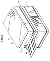
Figure 1 is a perspective view showing an
embodiment (Embodiment 1) of a recording apparatus to
which the present invention is applicable.
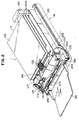
Figure 2 is a perspective view showing the
apparatus according to Embodiment 1 of the present invention
with the cover portion thereof removed.
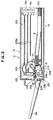
Figure 3 is a side sectional view of the apparatus
according to Embodiment 1.
Figure 4 is a side sectional view showing the
apparatus according to Embodiment 1 with the body unit
portion and the paper supply portion thereof separated
from each other.
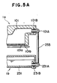
Figures 5A and 5B respectively are an illustration
showing an example of the construction of the connecting
portion between a recording head and a supply tube in
Embodiment 1 and between an ink tank and the supply tube
and a perspective view showing the essential portions
thereof.
Figure 6 is a perspective view showing another
embodiment of the present invention.
Figure 7 is a perspective view showing the
apparatus according to said another embodiment of the
present invention with the cover portion thereof removed.
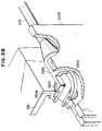
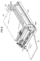
Figure 8 is a perspective view showing an example
of the construction of the essential portions of the
present invention.
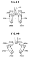
Figures 9A and 9B are side views for illustrating
the operation of the embodiment shown in Figure 8.
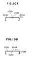
Figures 10A and 10B are side views showing two
examples of the construction of a platen which can be
adopted in the embodiment shown in Figure 8.
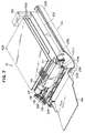
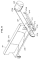
Figure 11 is a perspective view showing another
example of the construction of the essential portions of
the present invention.
Figure 12 is a perspective view showing still
another example of the construction of the essential
portions of the present invention.
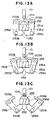
Figures 13A-13C are side views for illustrating
the operation of the embodiment shown in Figure 12.
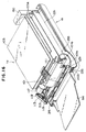
Figure 14 is a perspective view showing yet still
another example of the construction of the essential
portions of the present invention.
Figures 15A and 15B are side views for illustrating
the operation of the construction shown in Figure 14.
Figure 16 is a perspective view showing an
apparatus according to another embodiment of the present
invention with the cover portion thereof removed.
Figure 17 is a perspective view showing another
example of the construction of the essential portions of
the present invention.
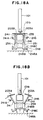
Figures 18A and 18B are side views for illustrating
the operation of the embodiment shown in Figure 17.
Figure 19 is a perspective view showing an
embodiment (Embodiment 2) of a recording apparatus provided
with image reading means to which the present
invention is applicable.
Figure 20 is a perspective view showing the apparatus
according to Embodiment 2 with the cover portion thereof
removed.
Figure 21 is a side sectional view of the apparatus
according to Embodiment 2.
Figure 22 is a side sectional view showing the
apparatus according to Embodiment 2 with the body unit
portion and the paper supply portion thereof separated
from each other.
Figures 23A and 23B respectively are an illustration
showing an example of the construction of the
connecting portion between a recording head and a supply
tube in Embodiment 2 and between an ink tank and the
supply tube and a perspective view showing the essential
portions thereof.
DESCRIPTION OF THE PREFERRED EMBODIMENTS
The invention will hereinafter be described in
detail with reference to the drawings.
〈Embodiment 1〉
Figure 1 is a perspective view showing an example
of the outer construction of an ink jet recording
apparatus which is a preferred embodiment of the present
invention, and Figure 2 is a perspective view showing
the ink jet recording apparatus with its outer cover
removed for convenience.
In Figures 1 and 2, the reference numeral 1
designates a body unit portion having an upper unit 1a
as a first unit and a lower unit 1b as a second unit.
The upper unit 1a is pivotable up and down relative to
the lower unit 1b about a hinge 11, as shown, for example,
in Figure 4. Of course, the upper unit 1a need not always
be made pivotable about the hinge 11. The upper unit 1a
is provided with a recording head 101, an electric circuit
portion 103, a fan 150, an upper discharge roller 115a,
an upper conveyor roller 113a, a paper guide 201 and a
paper supply roller 111 which will be described in detail.
On the other hand, the lower unit 1b is provided with a
platen 203, an ink absorbing member 235, an ink tank 231,
a paper cassette 221, a paper discharge tray 9A and idlers
213, 215. The reference numeral 5 denotes a cover disposed
over the upper side of the body unit portion 1.
The cover 5 is provided with an operating portion 7 in
which there are disposed various command switches 7a and
7b such as on-line switches with a host apparatus H and
a display device 7C for effecting the mode display. The
reference numeral 9 designates a discharge port formed in
one side of the apparatus. Recording mediums S on which
recording has been effected are piled on the discharge
tray 9A through the discharge port 9.
Figure 2 is a perspective view showing the
apparatus of Figure 1 with the cover 5 removed to illustrate
the interior construction of the apparatus of Figure
1, and Figure 3 is a side cross-sectional view of the
apparatus of Figure 1. In these figures, the reference
numeral 101 designates an ink jet recording head disposed
near the discharge port 9. The ink jet recording head 101
is in the form of the so-called full multi-type wherein
nozzles 101a are arranged, for example, at a density of
16 nozzles per 1 mm, over a range corresponding to the
full recording width (e.g., recording paper of format A4)
of the present apparatus. Also, use may be made of any
of methods in which electro-mechanical converting elements
(not shown) or electro-thermal converting elements (not
shown) are disposed at appropriate locations in the ink
flow paths such as the nozzles and discharge energy is
caused to act on ink in response to the supply of a
driving signal from the host apparatus H corresponding
to an image to be recorded, whereby ink is discharged
from the discharge ports 101b, but the latter type which
uses heat energy is excellent in that it is the high-accuracy
full multi-type. In the present embodiment,
the recording head 101 is provided in such a manner that
the discharge port 101b of each nozzle 101a opens vertically
downwardly.
The reference numeral 103 denotes the main
electric circuit portion of the present apparatus in
which a driver circuit for driving the recording head
101 through a flexible cable 102, a power source circuit,
a control circuit, various internal circuits of the
apparatus and an interface circuit with the host apparatus
H outside the apparatus are provided on a base plate 103A.
In the present embodiment, the main electric circuit
portion 103 is provided in the upper unit 1a in common
with the recording head 101 and therefore, even if the
ink discharge during recording or unexpected leakage of
ink has occurred, the ink has not exerted any influence
upon the electric circuit portion 103. That is, even if
the ink leaks out of the discharge ports 101b, the flow
path thereof is formed on the lower unit 1b side and thus,
in the present embodiment, the electric circuit portion
103 is disposed above the flow path, and the ink has
exerted no influence upon the main electric circuit
portion 103 of the present apparatus. Further, in the
present embodiment, the electric circuit portion 103 is
disposed at a level higher than the positions at which
the discharge ports 101b of the recording head 101 are
disposed. Thus, the ink has exerted no further influence
upon the electric circuit portion 103. The above-described
arrangement of the electric circuit portion 103 and the
discharge ports 101b has been effective, but has not always
been necessary.
The reference numeral 111 designates a paper
supply roller formed by cutting away a part of an arc.
The paper supply roller 111 is a roller for supplying
recording mediums S such as paper, films or cloths from
a cassette 221 containing the recording mediums S therein
to the recording station in which recording is effected
by the recording head 101.
The reference numerals 113 and 115 respectively
denote a conveyor roller disposed at the upstream side
on a recording medium conveyance path P with respect to
the recording station and a discharge roller disposed
near the discharge port 9 at the downstream side. These
rollers 113 and 115 are rotatively driven by a motor 117
through a timing belt 119. Thus, in response to this
rotative drive, the conveyor roller 113 and the discharge
roller 115 have cooperated with idlers 213 and 215
disposed in opposed relationship therewith to effect the
conveyance of the recording medium S to the recording
station with the recording medium S held therebetween and
the discharge of the recording medium S from the recording
station to the discharge tray 9A.
The reference numeral 201 designates a paper guide
provided on the conveyance path P of the recording mediums
S to restrict the conveyance path P, and the reference
numeral 203 denotes a platen provided on the lower unit
1b side in opposed relationship with the discharge ports
101b of the recording head 101 to maintain the recording
medium S in the recording station, that is, control the
recording surface, when recording is effected on the
recording medium S by the recording head 101.
The recording mediums S piled in the aforementioned
paper cassette 221 have been separated one by one by the
paper supply roller 111 through the cooperation thereof
with separating means (not shown) and conveyed toward the
recording station. The reference numeral 225 designates
the bottom plate of the apparatus. In the present embodiment,
this bottom plate 225 has served also as a partition
wall for blocking the outflow of leaking ink to the outside
of the apparatus when unexpected leakage of ink from the
recording head 101, etc. has occurred.
The reference numeral 231 designates an ink tank
as an ink supply source to the recording head 101. The
ink tank 231 is disposed below the platen 203 and designed
to supply ink to the recording head 101 through a flexible
supply tube 233. The reference numeral 235 denotes an
ink absorbing member formed of a water-absorbent porous
material. In the present embodiment, the ink absorbing
member 235 is disposed on top of the ink tank 231 below
the platen 203. This ink absorbing member 235 might
appropriately replace the platen 203 in position and be
constructed so as to be capable of opposing or bearing
against the discharge ports 101b of the recording head
101 and to be used for the discharge restoring operation
or the capping operation of the recording head 101.
Thereby, the ink dripping from the recording head 101 has
been appropriately collected.
The reference numeral 150 designates a fan for
introducing the air from the outside of the apparatus to
thereby cool the various portions of the apparatus. In
the present embodiment, this fan 150 has been disposed on
that side of the apparatus which is opposite to the
discharge port 9, whereby the air stream (indicated by
arrows a in Figure 3) from an air intake port 5a in said
side to the discharge port 9 has been produced. As
described above, in the present embodiment, the recording
head 101 has been provided near the discharge port 9 and
therefore, the satellite which may secondarily occur
during the discharge of ink droplets from the recording
head 101, the ink mist which may be caused on the surface
of the recording medium S by the scattering of ink, dust,
the paper powder of the recording medium, etc. have been
immediately carried out of the apparatus through the
discharge port 9 by riding on the air stream or by adhering
to the recording medium S or by both, whereby they could
be prevented from adhering to various parts in the apparatus
to contaminate them or break down the electric
circuit portion 103. That is, in the present embodiment,
the cooling fan 150 for cooling the electric circuit has
been shown with respect to a case where it is used also
as blower means in the apparatus which eliminates the ink
mist.
When the ink mist has been caused to adhere to
the recording medium S, it has exerted very little
influence upon the quality of printing, etc., because in
general, ink mist is very fine. Also, when the ink mist
is to be carried by the air stream, a filter or the like
might be provided near the discharge port 9 so that the
ink mist might be collected by it. If the ink mist has
been thus collected by the recording medium S or the
filter, the exterior walls or the like of the apparatus
have not been contaminated.
In addition to the above-described construction,
in the present embodiment, the body unit portion 1 has
been made separable into the upper unit 1a and the lower
unit 1b in the manner described below so as to facilitate
the repairs of various parts, the jam treatment, etc.
In Figure 4, there is shown an example of the
construction of a mechanism for separating the upper unit
1a and the lower unit 1b from each other and opening the
interior of the apparatus to thereby secure the space
available for the above-mentioned repairs and treatment.
In Figure 4, the reference numeral 11 designates a hinge
disposed on the side opposite to the discharge port 9 to
permit pivotal movement of the upper unit 1a relative to
the lower unit 1b, and the reference numeral 13 denotes
a spring for holding the upper unit 1a in its opened
position.
In the present embodiment, as described above,
the recording head 101, the rollers 113 and 115, etc. are
disposed near the discharge port 9 in the upper unit 1a,
and the platen 203, the idlers 213, 215, the paper cassette
221, the ink tank 231 and the ink absorbing member 235
are disposed near the discharge port 9 in the lower unit
1b and therefore, in the opened position of the body unit
portion 1 as shown in Figure 4, the ink system including
the recording head 101, the ink tank 231 and the ink
absorbing member 235 and the paper supplying or conveying
system including the paper cassette 221 and the roller
members have been widely opened.
That is, in the present embodiment, the upper unit
1a and the lower unit 1b become spaced apart from each
other along the path along which the recording medium S
is fed out from the cassette 221 to the discharge port 9
and thus, design has been made such that the conveyance
path is opened if the upper unit 1a is pivoted upwardly
relative to the lower unit 1b.
Accordingly, in this state, the work space necessary
for the repairs of various parts, the replacement
of the ink absorbing member and the elimination of jam
has been secured and thus, those works have become easy.
Also, in this state, the replenishment of recording
mediums S and the supply of ink might be done. The
present embodiment has been shown with respect to an
example in which the upper and lower units are spaced
apart from each other and opened along the entire
conveyance path of the recording medium S, whereas this
is not restrictive, but the above-described effect could
be attained if at least the portion of the recording
station by the recording head is opened.
The construction for thus securing the work space
is not limited to that shown in Figure 4, but could be
various. For example, a good result has been obtained
in any of a construction in which suitable struts for
supporting the upper unit 1a are provided at four corners
of the lower unit 1b and the upper unit 1a is made vertically
movable along the struts, a construction in which
the upper unit 1a is obliquely upwardly slidable in its
horizontal state by the use of a parallel link mechanism,
and a construction in which the upper unit 1a and the
lower unit 1b are not opened in the vertical direction
but are opened in the horizontal direction. Above all,
the hinge type of the present embodiment is simple in
construction and reliable in operation and has been very
preferable.
Now, in the present embodiment, in the ink system,
the recording head 101 has been disposed on the upper
unit 1a side and the ink tank 231 has been disposed on
the lower unit 1b side. Also, they have been designed to
communicate with each other through a supply tube 233.
Figure 5A is a schematic side sectional view showing the
connecting state of the supply tube, and Figure 5B is a
perspective view thereof.
In the present embodiment, as shown in Figure 5A,
pivotable ink joint members 101A and 231A are provided at
the connecting portion between the recording head 101 and
the ink supply tube 233 and the connecting portion between
the ink tank 231 and the ink supply tube 233, respectively,
so that the displacement of the body unit portion 1
resulting from the opening or closing thereof may be
absorbed by the rotation of the pivotable ink joint members
101A and 231A. In Figure 5A, the reference characters
101B and 231B designate O-rings for shutting off the ink.
Figure 5B shows the details of the connected
portion of the supply tube, and particularly shows the
construction thereof on the ink tank 231 side. In Figure
5B, the reference character 231D designates an elbow
provided integrally with the supply tube 233 at one end
thereof, the reference character 231C denotes a keep ring
for the O-ring 231B, and the reference character 231E
designates a keep plate for controlling the elbow 231D
vertically relative to the ink tank 231 and holding the
elbow 231D so as not to slip off from the ink tank 231.
The elbow 213D has been made rotatively slidable relative
to the ink tank 231, the O-ring 231B, the keep ring 231C
and the keep plate 231E.
Also, in the present embodiment, such a construction
has likewise been adopted on the recording head 101
side.
With such a construction, the supply tube 233 has
been made into a flexible tubular member formed of a
material such as polyethylene, whereby the upper unit 1a
and the lower unit 1b could be smoothly opened without a
great influence being exercised upon the ink flow path.
Further, in the present embodiment, the elbow 231D is
pivotable relative to the ink tank 231 and the recording
head 101 and therefore, when the upper unit 1a and the
lower unit 1b have been opened, the angle of mounting of
the supply tube 233 has been naturally displaced by the
resiliency of the supply tube itself.
By this, the slack of the supply tube 233 when
the upper unit 1a and the lower unit 1b remain closed
could be reduced and the amount of deformation of the
supply tube could be reduced. Also, by this, the supply
tube 233 could be made to have a length sufficient to
connect the ink tank 231 and the recording head 101
substantially linearly when the units 1a and 1b were
opened at a maximum angle of opening (see Figure 4) and
therefore, the flexibility required of the supply tube
233 could be designed to a small value. These facts have
made it realizable to make the supply tube thick and short.
This has also greatly contributed to the reduction in the
flow path resistance of the ink supply path from the ink
tank to the recording head, the prevention of the entry
of air into the line, and the compactness of the apparatus
resulting from the possibility of reducing the flexure
space for the supply tube 233.
The effect resulting from rotatably mounting the
supply tube as described above can be sufficiently expected
and therefore, a benefit could be obtained even if the
connecting portion shown in Figures 5A and 5B was provided
on only one of the ink tank 231 side and the recording
head 101 side.
The construction permitting the opening of the
units 1a and 1b is not limited to the above-described
construction comprising a combination of the flexible
supply tube and the pivotable joints, but use could be
made, for example, of a construction in which a relatively
rigid supply tube was connected through bellows or the
like.
Now, in the ink jet recording, the distance of
blight of an ink droplet, i.e., the distance between the
opening portion of the nozzle of the recording head 101
and the paper, is one of factors which greatly influence
the quality of recording. Particularly, in the case of
a structure in which as in the present embodiment, the
upper unit 1a having the recording head 101 and the lower
head 1b having the platen 203 which controls the paper
can be spaced apart from each other, it is desirable to
give consideration so that in the joined state of the
units, the recording head and the platen are accurately
opposed to each other in parallel relationship with each
other.
To realize this, it has been conceived, for example,
to hold the recording head 101 so as to be vertically
movable relative to the frame of the upper unit 1a, and
cause a dashing member fixed to the platen 203 of the
lower unit 1b to strike against a portion of the recording
head in the joined state of the upper and lower units.
So, in the present embodiment, to realize this
compactly and simply, design has been made such that the
recording head 101 is fixed to the upper unit 1a and the
platen 203 is fixed to the lower unit 1b and in the
joined state of the upper and lower units 1a and 1b,
dashing members (not shown) provided in the upper and
lower units are caused to strike against two points near
the opposite ends of the recording head 101. It has also
been preferable to provide suitable lock means to secure
said joined state.
According to this, it has become possible to
simply keep a highly accurate and well-reproducible
distance between the recording head and the paper during
the opening-closing of the upper and lower units 1a and
1b by accurately controlling the mounting dimensions of
the recording head 101 or the platen 203 relative to the
dashing members of the upper and lower units 1a and 1b.
In the ink jet recording apparatus according to
the present embodiment as described above, the on-demand
type recording head 101 has been disposed near the discharge
port 9 of the apparatus with the discharge ports
thereof facing vertically downwardly and the paper cassette
221 has been disposed below the electric circuit portion
103 so that a recording medium conveyance path including
the platen 203 is formed below the discharge ports of the
recording head and therefore, the conveyance distance of
the recording medium has been shortened and the conveying
system has been simplified and accordingly, the construction
of the apparatus could be made very compact.
Also, the main electric circuit portion 103 has
been provided on the upper unit 1a side in common with
the recording head 101 and therefore, even when the ink
has been discharged or when leakage of the ink has occurred,
the ink has not adversely affected the electric
circuit portion 103.
In addition, the internal pressure of the apparatus
has been made higher than the atmospheric pressure
so that there is formed an air stream flowing out through
the discharge port 9, whereby the ink mist produced during
the discharge of ink droplets by the head 101 provided
near the discharge port 9 and the paper powder or the
like produced by the conveyance of the recording medium
have been quickly carried out of the apparatus and thus,
the contamination or accident which would otherwise result
from the adherence of the ink to the various interior
parts in the apparatus has been reliably prevented.
Furthermore, the upper unit 1a has been made
pivotable relative to the lower unit 1b by the hinge 11
disposed on the side opposite to the discharge port 9,
whereby during the pivotal movement thereof, the ink
system and the conveying system have been widely opened
and accordingly, the work required for the repairs of
various parts and the jam treatment has become easy.
Also, the compactness of various parts including
the conveying system has been achieved by providing the
recording head near the discharge port, but the location
at which the recording head is disposed is not always
limited to the neighborhood of the discharge port. In
such case, an outflow port for air has been provided
separately near the recording head so that the ink mist,
etc. may be rapidly discharged, whereby the problems of
the ink mist, etc. could be solved.
Further, in the above-described embodiment, as
shown in Figures 2 and 3, each base plate 103A is horizontally
disposed and therefore, the air stream from
the fan 150 suffers very little from the loss by resistance
and is effectively directed to the vicinity of the
recording head 101 and the ink mist, paper powder, etc.
are rapidly discharged from the discharge port 9, but the
effect of the air stream could be made more reliable by
adopting a suitable arrangement. For example, it has
also been effective to incline each base plate 103A so
as to become lower toward the left as viewed in Figures 2
and 3 so that the air stream from the fan 150 directly
impinges on the discharge ports of the recording head 101.
Also, it has been possible to provide a duct 180
having an opening 180A opposed to the fan 150 and an opening
180B opposed to the recording head 101, as shown in
Figure 6, so that the air stream is directed to the
recording head 101 through the duct 180.
Further, instead of the cooling fan 150 being
used also as a blower as described above, blower means
forming a flow of air might be disposed separately at a
suitable location. Also, an effect has been found in
driving this blower means only during printing, and by
doing so, it has been possible to minimize the desiccation
of the nozzles 101a, etc. of the recording head 101.
In any case, the blower means used to eliminate
the ink mist could be any one which would increase the
internal pressure of the apparatus slightly above the
atmospheric pressure, and has been sufficiently effective
even if the air stream formed thereby is minute.
Also, the present embodiment has been described
with respect to a case where the host apparatus H is
employed as the recording data supply source, but of
course, such a data supply source may be any one. For
example, instead of or in addition to the host apparatus
H, reading means for reading the image of an original
may be provided on top of the upper unit 1a and the read
image information may be converted into an electrical
signal which in turn may be supplied to the recording
head 101. A preferred embodiment provided with such
image reading means will be described later as a second
embodiment.
The construction around the platen of the recording
apparatus of the present invention will now be described
with reference to Figure 7. The reference numeral 203
designates the platen provided on the lower unit 1b side
in opposed relationship with the recording head 101 to
control the recording surface. The platen 203 has been
made movable from its position opposed to the recording
head 101, by a driving portion to be described which is
not shown in Figure 7.
The recording mediums piled on the aforementioned
paper cassette 221 are separated one by one by the paper
supply roller 111 through the cooperation thereof with
separating means (not shown) and are conveyed toward the
recording station. Designated by 225 is the bottom plate
of the apparatus. In the present embodiment, the bottom
plate 225 has been used also as a partition wall for
blocking the outflow of leaking ink to the outside of
the apparatus when unexpected leakage of ink from the
recording head 101, etc. has occurred.
The reference numeral 233 designates a flexible
supply tube for communicating the recording head with an
ink tank, not shown, as an ink supply source. The reference
numeral 235 denotes an ink absorbing member formed
of a water-absorbent porous material. In the present
embodiment, the ink absorbing member 235 has been disposed
below the platen 203. The ink absorbing member 235 could
be designed so as to be capable of appropriately replacing
the platen 203 in position and being opposed or joined
to the discharge ports of the recording head 101 so that
the ink absorbing member could be used for the restoration
of the discharge of the recording head 101 and for the
capping of the recording head.
Thereby the ink has been appropriately collected
from the recording head 101 side.
The reference numeral 150 designates a fan for
introducing the air from the outside of the apparatus
and thereby cooling various parts of the apparatus.
In the present embodiment, this fan 150 has been
disposed on that side of the apparatus which is opposite
to the discharge port 9 for the recording medium,
whereby the air stream from an air intake port 5a in
said side to the discharge port 9 has been produced.
As described above, in the present embodiment, the
recording head 101 has been provided near the discharge
port 9 and therefore, the satellite which may secondarily
occur during the discharge of ink droplets from the
recording head 101, the ink mist which may be caused
on the surface of the recording medium by the scattering
of ink, dust, the paper powder of the recording medium,
etc. have been immediately carried out of the apparatus
through the discharge port 9 by riding on the air
stream, whereby they could be prevented from adhering
to various parts in the apparatus to contaminate them
or break down the electric circuit portion 103. In
the present embodiment, the cooling fan 150 for cooling
the electric circuit portion 103, etc. has been used
also as blower means in the apparatus which eliminates
the ink mist.
Figure 8 shows an example of the construction
of a driving portion for the platen according to the
present invention. The reference characters 203A and
203B designate platen members forming the platen 203
in the joined state shown. The platen members 203A
and 203B are connected through arms 251A and 251B to
shafts 253A and 253B extending lengthwise of the
recording head 101, and are pivotable about these shafts
253A and 253B in a direction to open the recording
surface. Gears 255A and 255B are provided on the
ends of the shafts 253A and 253B, respectively, and
through these gears 255A and 255B, the platen members
are connected to a set of gears 257A and 257B meshing
with each other, so that the directions of pivotal
movement of the platen members 203A and 203B for opening/forming
the recording surface may be opposite to each
other. The transmission mechanism including these
gears are combined with a motor 260 through a gear
259, and by controlling the direction of revolution of
the motor 260, predetermined pivotal movement of the
platen members 203A and 203B has been made possible.
That is, as shown in Figure 9A, during recording,
the dashing surface 204A of the platen member 203A
and the dashing surface 204B of the platen member 203B
are held in their joined state, whereby the platen
members 203A and 203B are designed to form the platen
203 for controlling the recording surface of the
recording medium by the recording head 101. In contrast,
during maintenance, as shown in Figure 9B, the platen
members 203A and 203B are opened to the left and right
as viewed in the figure by driving the motor 260, through
the transmission mechanism, whereby a space is secured
below the recording head 101 and, for example, by
joining the ink absorbing member to the discharge
ports of the recording head 101, it has become possible
to effect cleaning or effect the discharge restoring
operation such as preliminary discharge with the ink
absorbing member being proximately opposed to the
discharge ports of the recording head. Such joining
or proximate disposition of the ink absorbing member may
be accomplished as by inserting the absorbing member
from a suitable location on the apparatus, or could be
accomplished by bringing the ink absorbing member into
proximity to the discharge ports of the recording head
by a suitable mechanism through the space secured with
movement of the platen members 203A and 203B.
In the present embodiment, the platen 203
has been constructed of the two members 203A and 203B
so that during recording, the dashing surfaces 204A
and 204B are joined together and therefore, when a
recording medium has been conveyed, there has occurred
a case where the forward movement of the leading end
edge of the recording medium is hampered in this
dashing portion to cause jam.
Figures 10A and 10B show two examples of the
construction of the platen members 203A and 203B for
smoothing the movement of the recording medium and
preventing jam as a countermeasure for such jam. First,
Figure 10A shows an example in which the both dashing
surfaces 204A and 204B are provided with curved
surfaces, and by these curved surfaces, the leading end
edge of the recording medium has been smoothly guided
in the direction of movement indicated by arrow in
Figure 10A. Figure 10B shows an example in which the
dashing surface 204B of the platen member 203B lying at
the downstream side in the direction of movement of
the recording medium is provided with an inclined
surface downwardly inclined with respect to the direction
of movement of the recording medium, and occurrence
of jam could also be prevented in the dashing portion
by such a construction.
In the above-described construction, the
transmission mechanism comprising the motor 260 and the
gear train has been provided to make the two platen
members 203A and 203B pivotable, but alternatively,
for example, a solenoid might be used during the
driving and an appropriate link mechanism might be
disposed so that the pivotal movement of the platen
members 203A and 203B might be accomplished.
Figure 11 shows a further example of the
construction of the platen driving portion. In this
example, the platen 203 is a unitary member which is
movable in the horizontal plane in a direction orthogonal
to the lengthwise direction of the recording head 101,
i.e., the direction of conveyance of the recording
medium.
In Figure 11, the reference characters 270A
and 270B designate pulleys over and between which is
extended a wire 267 for moving the platen 203 in the
direction of arrow. The reference numeral 265 denotes
a motor coupled to one pulley 270B to move the platen
203 through the wire 267. The reference numeral 271
designates a wire fixing bed which is provided on the
platen 203 to fix the platen to the wire 267. The
reference numeral 273 denotes wheels provided on the
platen 203 to move the platen 203 smoothly along a
guide rail 275 extending in the direction of arrow.
The reference characters 275A and 275B designate
stoppers provided on the guide rail 275 and engageable
by the wheels 273 to position the platen 203 at a
position opposed to the recording head 101 and a
position spaced apart from the recording head 101.
By such a construction as well, during
recording, the platen 203 is positioned at the shown
position to control the recording surface of the
recording medium, while during maintenance, the motor
265 is driven to position the platen 203 at the position
of the stopper 275B, whereby a large work space could
be secured below the recording head 101 to improve the
working property.
Another mode of the construction around the
platen of the recording apparatus of the present
invention will now be described with reference to the
drawings.
Figure 12 shows an example of the construction
of the platen driving portion according to the present
invention. The reference characters 203A and 203B
designate platen members forming the platen 203 in
their joined state shown. The platen members 203A
and 203B are connected through arms 251A and 251B to
shafts 253A and 253B, respectively, extending lengthwise
of the recording head 101 and are pivotable about these
shafts 253A and 253B in a direction to open the recording
surface. Gears 255A and 255B are provided on the ends
of the shafts 253A and 253B, respectively, and through
these gears 255A and 255B, the platen members are
connected to a set of gears 257A and 257B meshing with
each other so that the directions of pivotal movement
of the platen members 203A and 203B for opening/forming
the recording surface are opposite to each other. The
transmission mechanism including these gears is combined
with a motor 260 through a gear 259, and by controlling
the direction of revolution of this motor 260, predetermined
pivotal movement of the platen members 203A and
203B has been made possible.
Also, the lower portions of the arms 251A and
251B have been made to extend inwardly from their mounted
portions with respect to the shafts 253A and 253B and
those inwardly extending portions have been engaged
with the bottom surface of a case 235A in which an
ink absorbing member 235 is contained.
The operation of the driving portion for the
platen 203 and the ink absorbing member 235 will now
be described with reference to Figures 13A - 13C.
First, as shown in Figure 13A, during recording,
the dashing surface 204A of the platen member 203A
and the dashing surface 204B of the platen member 203B
are held in their joined state, whereby the platen
members 203A and 203B have been designed to form the
platen 203 for controlling the recording surface of the
recording medium by the recording head 101. Also,
design has been made such that at this time, the
inwardly extending portions 252 of the respective arms
are engaged with the bottom surface of the case 235A
in their substantially horizontally kept state and
therefore, the ink absorbing member 235 has been
positioned below the platen members 203A and 203B.
In contrast, when the elimination of the
desiccation or clogging of the ink in the nozzles
including the discharge ports, the elimination of
bubbles mixed with the ink or the discharge for
replacing the viscosity-increased ink with fresh ink
(the preliminary discharge) has been effected, the
motor 260 has been driven. Thereupon, as shown in
Figure 13B, the platen members 203A and 203B have been
opened to the left and right as viewed in the figure
through the transmission mechanism and at the same time,
the arm portions 252 have been pivoted upwardly about
the shafts 253A and 253B. The ink absorbing member
235, together with the case 235A, has been pushed up
and disposed so as to be directly opposed to the
underside of the recording head 101. Thus, the
discharge restoring operation by the preliminary
discharge has become possible. Such a discharge
restoring operation by the preliminary discharge could
be accomplished by driving the motor 260 at a suitable
chance before or during the recording operation and
thereby driving the recording head with the absorbing
member opposed thereto.
Further, the cleaning of the end surface
including the discharge ports could be accomplished by
pivotally moving the arms 251A and 251B from their state
of Figure 13B and joining the ink absorbing member 235
to the discharge ports of the recording head 101, as
shown in Figure 13C. Thus, the ink, etc. adhering to
the end surface of the discharge ports have been
immediately absorbed by the ink absorbing member 235
and the restoration of discharge by cleaning has been
accomplished. If an elastic member formed of silicone
rubber or like material is disposed instead of the ink
absorbing member 235, the function of capping which
protects the vicinity of the discharge ports from
desiccation or entry and adherence of dust or the like
during the non-use of the apparatus would be performed.
Again in the present embodiment, the platen 203
has been constructed of the two members 203A and 203B
and design has been made such that the dashing surfaces
204A and 204B are joined together during recording and
therefore, there have been cases where the movement of
the leading end edge of the recording medium is
hampered in the dashing portion to cause jam when the
recording medium is conveyed.
However, as described in connection with the
previous example, the occurrence of jam could be
prevented by adopting the shape of the platen as shown
in Figures 10A and 10B.
In the above-described embodiment, the
transmission mechanism comprising the motor 260 and the
gear train has been provided to enable the two arms
251A and 251B to be pivotally moved, but the same purpose
could also be achieved, for example, by using a solenoid
during the driving and disposing an appropriate link
mechanism to thereby pivotally move the platen members
203A and 203B.
Figure 14 shows still a further example of the
construction of the platen driving portion. In this
example, the platen 203 comprises a unitary member and
is made moveble in a horizontal plane in a direction
orthogonal to the lengthwise direction of the recording
head 101, i.e., the direction of conveyance of the
recording medium, and the ink absorbing member 235
is vertically movable with the movement of the platen.
In Figure 14, the reference characters 270A
and 270B designate pulleys over and between which is
extended a wire 267 for moving the platen 203 in the
direction of arrow. The reference numeral 265 denotes
a motor coupled to one pulley 270B to move the platen
203 through the wire 267. The reference numeral 271
designates a wire fixing bed which is provided on the
platen 203 to fix the platen to the wire 267. The
reference numeral 273 denotes wheels combined with the
platen 203 to move the platen 203 smoothly along a
guide rail 275 extending in the direction of arrow.
The reference characters 275A and 275B designate
stoppers provided on the guide rail 275 and engageable
by the wheels 273 to position the platen 203 at a
position opposed to the recording head 101 at a position
for joining the ink absorbing member 235 to the
recording head 101.
The reference numeral 281 denotes a guide member
combined integrally with the platen 203. The guide
member 281 is provided with a cam surface 281A engageable
with a guide pin 283 projectedly provided on a case 235A
containing the ink absorbing member 235 therein to
thereby permit vertical movement of the ink absorbing
member 235. The case 235A is normally biased upwardly
by a bias member such as a spring (see Figures 15A
and 15B), and the upward movement thereof has been
controlled by the guide pin 283.
The reference numeral 290 designates a fixed
bed which is fixed to the apparatus, and the reference
numeral 292 denotes a parallel link which connects the
fixed bed 280 to the case 235A. The falling of the ink
absorbing member 235 during the vertical displacement
thereof has been prevented thereby.
In such a construction, design has been made
such that during recording, the platen 203 is positioned
near the stopper 275A as viewed in Figure 14 so as to
form the recording surface of the recording medium.
That is, in this state, as shown in Figure 15A, the cam
surface 281A of the guide 281 has positioned the ink
absorbing member 235 in its lowered position against
the bias force of a spring 294 through the guide pin
283.
In contrast, when the discharge restoring
operation by cleaning or the capping operation is to
be effected, the motor 265 has been driven to move
the platen 203 and position it near the stopper 275B.
Design has been made such that in this state, with the
movement of the guide 281 in the direction X, the ink
absorbing member 235 is moved up by the action of the
spring 294 to be joined to the discharge ports of the
recording head 101 while the guide pin 283 is engaged
with the cam surface 281A, as shown in Figure 15B.
If the motor 265 is controlled to appropriately
position the platen 203 between the stoppers 275A and
275B, the ink absorbing member 235 becomes opposed to
the recording head 101 with a proper distance kept
therebetween and therefore, the discharge restoring
operation by preliminary discharge could be performed.
Another embodiment of the recording apparatus
of the present invention will hereinafter be described
with reference to the drawings.
A schematic perspective view of this embodiment
is shown in Figure 16. The reference numerals given in
Figure 16 are similar in significance to those given in
Figure 2 and therefore need not be described in detail.
In the present embodiment, the platen 203 is
made movable from its position opposed to the recording
head 101 by a driving portion, not shown. That is,
as will be described later, in the present embodiment,
the ink absorbing member 235 is designed so as to be
capable of appropriately replacing the platen 203 in
position in response to movement of the platen and being
opposed or joined to the discharge ports of the
recording head 101 for use in the discharge restoring
operation of the recording head 101. Thereby the ink
from the recording head 101 has been appropriately
collected during recording.
Also, in the present embodiment, the ink
absorbing 235 is disposed below the platen 203 integrally
with the ink tank 231.
The present embodiment will be described in
greater detail.
Figure 17 shows an example of the construction
of the essential portions of the present invention.
In Figure 17, the reference numeral 234 designates a
cartridge containing therein the ink tank 231 and the
ink absorbing member 235 as a unit, and the reference
character 234A denotes a joint for connecting the ink
tank 231 to the supply tube 233. The reference characters
203A and 203B designate platen members adapted
to form the platen 203 in their joined state (the state
in which they cover the upper surface of the ink
absorbing member 235). The platen members 203A and
203B are connected, for example, integrally to the
cartridge 234 through a link 241 and are made pivotable
about pivots on the cartridge 234 in a direction to
uncover the upper surface of the ink absorbing member
235 and a direction to cover the upper surface of the
ink absorbing member 235. For example, the link 241
and the cartridge 234 might be connected together by
a tension spring so that when no extraneous force is
applied, the platen members 203A and 203B might be
pivotally moved in the direction to cover the upper
surface of the ink absorbing member 235. These platen
members may function as a protective member for
protecting the ink absorbing member. Also, the pivots
of the platen members 203A and 203B by the link 245
might be appropriately determined so that the platen
members 203A and 203B might normally cover the upper
surface of the ink absorbing member 235, or there has
been no problem even when a spring has been combined
therewith.
In the present embodiment, the cartridge 234 on
which the platen members 203A and 203B are mounted has
been made movable in the vertical direction of arrow B
by a suitable driving member. Also, the link 241 has
been provided with an opening-closing shaft 241A which
comes into engagement with a member fixed to the
apparatus with the upward displacement of the cartridge
234 by the driving member 248 and opens the platen
members 203A and 203B with said engagement. Further,
the cartridge 234 has been made removably mountable with
respect to the apparatus so that the ink tank 231 and
the ink absorbing member 235 can be interchanged as
a unit. The direction in which the ink cartridge 234
is taken out could be, for example, the lengthwise
direction thereof as indicated by arrow A. The platen
members 203A and 203B are engaged with the cartridge
234 through the link 241.
The operation of the construction of Figure 17
will now be described with reference to Figures 18A and
18B. In these figures, the reference numeral 245
designates a fixed wall which is fixed to the apparatus
and serves as an engagement member engageable with the
opening-closing shaft. The reference numeral 248
denotes a cam as a driving member having an arm
portion 248B engaged with the bottom surface of the
cartridge 234 and pivotable about a pivot 248A fixed
to the apparatus. Also, the other arm portion 248C
of the cam 248A has been coupled to drive means such as
a motor or a solenoid through a suitable transmission
mechanism so that during the discharge restoring
operation, the drive means may be driven to thereby
move the cartridge 234 upwardly.
That is, as shown in Figure 18A, when the
cartridge 234 is held in its lower position during
recording, the fixed wall 245 and the opening-closing
shaft 241A are not in engagement with each other in
this state and therefore, the platen members 203A and
203B are in a position wherein they abut with each
other and cover the ink absorbing member 235, so that
they restrict the recording surface of the recording
medium in opposed relationship with the discharge ports
of the recording head 101.
In contrast, design has been made such that
when the end surface of the recording head 101
including the discharge ports 101b is to be cleaned,
the drive means is appropriately driven so that the arm
portion 248B of the cam 248 pushes the cartridge 234
upwardly. Along with this, the shaft 241A has come
into engagement with the fixed wall 245 and the platen
members 203A and 203B have been pivotally moved in
the direction to uncover the upper surface of the ink
absorbing member 235 while, at the same time, the ink
absorbing member 235 has been joined to the discharge
ports of the recording head 101. Thus, the ink, etc.
adhering to the end surface of the discharge ports
have been immediately absorbed by the ink absorbing
member 235 and the restoration of discharge by cleaning
has been accomplished.
Where a motor is used as the drive means for
the cam 248, if the angle of revolution of the motor
is appropriately controlled to thereby position the
cartridge 234 at a position between the positions of
Figures 18A and 18B, the upper surface of the ink
absorbing member 235 is uncovered and becomes opposed
to the recording head 101 with a proper distance kept
therebetween and therefore, the elimination of the
desiccation and clogging of the ink near the discharge
ports 101b, the elimination of bubbles mixed with the
ink, or the discharge for replacing the viscosity-increased
ink with fresh ink (the preliminary discharge)
has become possible, and the discharge restoring
operation by the preliminary discharge could be
performed.
If, with such absorption of the ink from the
recording head 101 being taken into account, the
absorbing capacity of the ink absorbing member 235
(the amount of ink which can be absorbed by the ink
absorbing member) is set to a value greater than the
initial amount of ink in the ink tank 231, it has been
possible without any special means for detecting the
amount of ink in the ink absorbing member being provided
to prevent the inconvenience that the ink which could
not completely absorbed by the ink absorbing member 235
leaks therefrom to contaminate various parts in the
apparatus or the cartridge 234 is interchanged with
unused ink left therein. Of course, this is also
applicable to the ink absorbing member shown in the
aforedescribed embodiment.
Also, during the removal of the cartridge 234,
the platen members 203A and 203B have provided a lid
member for covering the ink absorbing member 235 and
thus, the ink has not contaminated the operator's
hand or the like during the interchange of the cartridge.
Again in the present embodiment, the platen 203
has been constructed of the two members 203A and 203B
and design has been made such that these platen members
are dashed against each other and joined together
during recording and therefore, when the recording
medium has been conveyed, there have been cases where
the movement of the leading end edge of the recording
medium is hampered in the dashing portion to cause jam.
However, again in the present embodiment, such problem
could be solved by the application of the construction
shown in Figures 10A and 10B.
Now, in the present embodiment, in the ink
system, the recording head 101 is disposed on the upper
unit 1a side and the ink tank 231 is disposed on the
lower unit 1b side and they are communicated with each
other through the supply tube 233 and therefore, it has
been preferable that as previously described, a
pivotable ink joint member be provided, for example,
in at least one of the connecting portion between the
recording head 101 and the ink supply tube 233 and the
connecting portion between the ink tank 231 and the ink
supply tube 233 so that the displacement resulting
from the vertical movement of the cartridge 234 may be
absorbed by the pivotable ink joint. Also, instead of
the flexible supply tube 233, use might safely be made
of a supply tube comprising two relative rigid tube
members coupled together through retractile bellows.
While Embodiment 1 has been described with
respect to a case where the present invention is
applied to an ink jet recording apparatus having an
on-demand type recording head using a discharge energy
generating member represented by an electro-thermal
converting element and having discharge ports disposed
downwardly, the present invention is of course
effectively and readily applicable also to recording
apparatuses adopting various drive systems and
arrangements.
Description will now be made of a case where
image reading means is provided in the recording
apparatus of the present invention.
〈Embodiment 2〉
Embodiment 2 will hereinafter be described in
detail with reference to the drawings.
Figure 19 is a perspective view showing an
example of the outer construction of a recording
apparatus provided with image reading means, and Figure
20 is a perspective view showing the recording apparatus
with its outer cover removed for convenience.
In Figures 19 and 20, the reference numeral
1 designates a body unit portion having an upper unit
1a as a first unit and a lower unit 1b as a second
unit. The upper unit 1a has been made pivotable up
and down about a hinge 11 relative to the lower unit
1b. The upper unit 1a is provided with a recording
head 101, an electric circuit portion 103, a fan 150, an
upper discharge roller 115a, an upper conveyor roller
113a, a paper guide 201 and a paper supply roller 111
which will be described later. On the other hand, the
lower unit 1b is provided with a platen 203, an ink
absorbing member 235, an ink tank 231, a paper cassette
221, a paper discharge tray 9A and idlers 213, 215. The
reference numeral 5 denotes a cover disposed over the
body unit portion 1. The cover 5 has an operating
portion 7 in which are disposed various command switches
7a and 7b such as on-line switches and a display
device 7c for effecting the mode display, and in
addition, an insertion port 8A for a medium (an original)
bearing image information to be read, and a discharge
port 8B for the read original, and is provided with an
original reading apparatus containing portion 8 which
covers a reading apparatus to be described with
reference to Figure 20. The reference numeral 9
designates a discharge port provided in one side of
the apparatus. Recording mediums S on which recording
has been effected may be piled on the discharge tray
9A through the discharge port 9.
Figure 20 is a perspective view showing a
state in which the cover 5 of the apparatus shown in
Figure 19 has been removed to illustrate the interior
construction of the Figure 19 apparatus, and Figure
21 shows a side cross-section of the apparatus shown in
Figure 19. In these figures, the reference numeral 101
designates an image processing head disposed near the
discharge port 9. The image processing head 101 is in
the form of the so-called full multi-type wherein
nozzles 101a are arranged, for example, at a density of
16 nozzles per 1 mm, over a range corresponding to the
full recording width (e.g. recording paper of format
A4) of the present apparatus. Also, discharge energy
generating members represented by electro-mechanical
converting elements (not shown) or electro-thermal
converting elements (not shown) are disposed at
appropriate locations in the ink flow paths such as
the nozzles and discharge energy has been caused to
act on ink in response to the supply of a driving
signal corresponding to an image to be recorded (i.e.,
a driving signal corresponding to the reading signal of
an original reading apparatus 800), whereby ink has been
discharged from the discharge ports 101b. In the
present embodiment, the recording head 101 is provided
in such a manner that the discharge port 101b of each
nozzle 101a opens vertically downwardly.
The reference numeral 103 denotes the main
electric circuit portion of the present apparatus in
which a driver circuit for driving the recording head
101 through a flexible cable 102, a driver circuit for
the original reading apparatus 800, a signal processing
circuit, a power source circuit, a control circuit, an
interface circuit with the various circuits in the
apparatus, etc. are provided on a base plate 103A.
In the present embodiment, the main electric circuit
portion 103 is provided in the upper unit 1a in common
with the recording head 101 and therefore, even if the
ink discharge during recording or unexpected leakage of
ink has occurred, the ink has not exerted any influence
upon the electric circuit portion 103. That is, even
if the ink leaks out of the discharge ports 101b, the
flow path thereof is formed on the lower unit 1b side
and thus, in the present embodiment, by the electric
circuit portion 103 being disposed above the flow path,
the ink has exerted no influence upon the main electric
circuit portion 103. Further, in the present embodiment,
the electric circuit portion 103 is disposed at a level
higher than the positions at which the discharge ports
101b of the recording head 101 are disposed. Thus, it
has become more difficult for the ink to exert an
influence upon the electric circuit portion 103. The
above-described arrangement of the electric circuit
portion 103 and the discharge ports 101b has been a
preferable arrangement, but has not always been
necessary.
The reference numeral 111 designates a paper
supply roller formed by cutting away a part of an arc.
The paper supply roller 111 is a roller for supplying
recording mediums S such as paper, films or cloths
from a cassette 221 containing the recording mediums
S therein toward the recording station in which recording
is effected by the recording head 101.
The reference numerals 113 and 115 respectively
denote a conveyor roller disposed at the upstream side
on a recording medium conveyance path P with respect to
the recording station and a discharge roller disposed
near the discharge port 9 at the downstream side.
These rollers 113 and 115 are adapted to be rotatively
driven by a motor 117 through a timing belt 119.
Thus, in response to this rotative drive, the conveyor
roller 113 and the discharge roller 115 have cooperated
with idlers 213 and 215 disposed in opposed relationship
therewith to effect the conveyance of the recording
medium S to the recording station with the recording
medium S held therebetween or the discharge of the
recording medium S from the recording station to the
discharge tray 9A.
The reference numeral 201 designates a paper
guide provided on the conveyance path P of the
recording mediums S to restrict the conveyance path P,
and the reference numeral 203 denotes a platen provided
on the lower unit 1b side in opposed relationship with
the discharge ports 101b of the recording head 101 to
maintain the recording medium S in the recording station,
that is, control the recording surface, when recording
is effected on the recording medium S by the recording
head 101.
The recording mediums S piled in the aforementioned
paper cassette 221 are separated one by one
by the paper supply roller 111 through the cooperation
thereof with separating means (not shown) and
conveyed toward the recording station. The reference
numeral 225 designates the bottom plate of the apparatus.
In the present embodiment, this bottom plate 225 has
served also as a partition wall for blocking the outflow
of leaking ink to the outside of the apparatus when
unexpected leakage of ink from the recording head 101,
etc. has occurred.
The reference numeral 231 denotes an ink tank
as an ink supply source to the recording head 101. The
ink tank 231 is disposed below the platen 203 and
designed to supply ink to the recording head 101 through
a flexible supply tube 233. The reference numeral 235
designates an ink absorbing member formed of a water-absorbent
porous material. In the present embodiment,
the ink absorbing member 235 is disposed on top of the
ink tank 231 below the platen 203. As in Embodiment 1,
this ink absorbing member 235 might appropriately
replace the platen 203 in position and be constructed
so as to be capable of opposing or bearing against
the discharge ports 101b of the recording head 101 and
to be used for the discharge restoring operation or the
capping operation of the recording head 101. Thereby,
the ink dripping from the recording head 101 could be
appropriately collected.
The reference numeral 150 designates a fan for
introducing the air from the outside of the apparatus
to thereby cool the various portions of the apparatus.
In the present embodiment, this fan 150 has been
disposed on that side of the apparatus which is opposite
to the discharge port 9, whereby the air stream
(indicated by arrows a in Figure 20) from an air intake
port 5a in said side to the discharge port 9 has been
produced. As described above, in the present embodiment,
the recordings head 101 has been provided near the
discharge port 9 and therefore, the satellite which
may secondarily occur during the discharge of ink
droplets from the recording head 101, the ink mist which
may be caused on the surface of the recording medium S
by the scattering of ink, dust, the paper powder of
the recording medium, etc. have been immediately carried
out of the apparatus through the discharge port 9 by
riding on the air stream, whereby they could be prevented
from adhering to various parts in the apparatus including
the original reading apparatus 800 to contaminate them
or break down the electric circuit portion 103. In
the present embodiment, the cooling fan 150 for cooling
the electric circuit has been used also as blower means
in the apparatus which eliminates the ink mist.
The reference numeral 800 denotes an original
reading apparatus disposed above the electric circuit
portion 103. The original reading apparatus 800 has
a sensor unit 801 for reading image information (for
example, a contact sensor unit as shown), an original
feeding roller 813 for feeding an original M inserted
into the insertion port 8A toward the sensor unit 801,
and an original discharging roller 815 for discharging
the read original M from the discharge port 8B.
The sensor unit 801 is provided with an
illuminating device 803 for illuminating the position
at which the original conveyed between the rollers 813
and 815 is read, and a line sensor 805 in which light-receiving
elements are arranged so that one-line
reading can be accomplished over the full width of
the original. The image information read thereby has
been directed to a suitable processing circuit provided
in the electric circuit portion 103, and the recording
head 101 has been driven for the thus processed image
information, whereby image formation could be accomplished.
The rollers 813 and 815 in the original
reading apparatus are coupled to and driven by the
motor 117 through a transmission mechanism including a
timing belt 819 and a gear 821 and are designed to
cooperate with idlers 823 and 825 disposed in opposed
relationship with the respective rollers to convey the
original.
In addition to the above-described construction,
in the present embodiment, the body unit portion 1 is
made separable into the upper unit 1a and the lower
unit 1b as will be described below to facilitate
repairs of various parts and jam treatment.
Figure 22 shows an example of the construction
of a mechanism for separating the upper unit 1a and the
lower unit 1b from each other and opening the interior
of the apparatus to thereby secure a space available
for said works. In Figure 22, the reference numeral
11 designates a hinge disposed on the side opposite to
the discharge port 9 to permit pivotal movement of
the upper unit 1a relative to the lower unit 1b, and
the reference numeral 13 denotes a spring for holding
the upper unit 1a in its opened position.
In the present embodiment, as described above,
the recording head 101, the rollers 113 and 115, etc.
are disposed near the discharge port 9 in the upper
unit 1a, and the platen 203, the idlers 213, 215, the
paper cassette 221, the ink tank 231 and the ink
absorbing member 235 are disposed near the discharge
port 9 in the lower unit 1b and thus, design is made
such that in the opened state of the body unit portion
1 as shown in Figure 22, the ink system including the
recording head 101, the ink tank 231 and the ink
absorbing member 235 and the paper supplying or
conveying system including the paper cassette 221 and
the various roller members are widely opened.
That is, in the present embodiment, the
upper unit 1a and the lower unit 1b become spaced
apart from each other along a path along which the
recording medium S is fed out from the cassette 221 to
the discharge port 9 and therefore, when the upper
unit 1a has been pivoted upwardly relative to the lower
unit 1b, the conveyance path has been opened.
Accordingly, the work space required for
repairs of various parts, interchange of the ink
absorbing member and jam eliminating process has been
secured in this state and thus, those works have become
easy. Also, replenishment of recording mediums S and
supply of ink might be effected in this state. The
present embodiment has been shown with respect to an
example in which the upper and lower units are spaced
apart and opened along the entire conveyance path of
the recording medium S, whereas this is not restrictive,
but the above-described effect could be attained by
making design such that at least the portion of the
recording station by the recording head is spaced apart
and opened.
The construction for thus securing the work
space is not limited to that shown in Figure 22, but
could be various. For example, suitable struts for
supporting the upper unit 1a might be provided at four
corners of the lower unit 1b and the upper unit 1a might
be made vertically movable along those struts, or the
upper unit 1a might be slidden obliquely upwardly in
its horizontal state by the use of a parallel link
mechanism, or the direction in which the upper unit 1a
and the lower unit 1b are opened is not limited to the
vertical direction, but for example, the upper unit and
the lower unit might be opened in the horizontal
direction.
Now, in the present embodiment, in the ink
system, the recording head 101 has been disposed on
the upper unit 1a side and the ink tank 231 has been
disposed on the lower unit 1b side, and they have been
designed to communicate with each other through a
supply tube 233.
Again in the present embodiment, the supply
tube 233 could be connected by the use of the connecting
method as described in Embodiment 1 with reference to
Figures 5A and 5B.
This portion is shown in Figures 23A and 23B,
but the construction, etc. thereof has been described
in detail in Embodiment 1 with reference to Figures 5A
and 5B and therefore, the details thereof including
the effect thereof need not be described.
Now, in ink jet recording, the distance of
flight of ink droplet, i.e., the distance between the
nozzle opening portion of the recording head 101 and
the paper, is one of factors which greatly influence
the quality of recording, as proviously described.
Again in the present embodiment, as in Embodiment 1,
the upper unit 1a having the recording head 101 and the
lower unit 1b having the platen 203 for controlling
the paper can be spaced apart from each other and
therefore, it is desirable to give consideration so
that in the joined state of the units, the recording
head and the platen are accurately opposed to each other
in parallel relationship with each other.
To realize this, it has been conceived, for
example, to hold the recording head 101 so as to be
vertically movable relative to the frame of the upper
unit 1a, and cause a dashing member fixed to the
platen 203 of the lower unit 1b to strike against a
portion of the recording head in the joined state of
the upper and lower units.
In the present embodiment, to realize this
compactly and simply, design has been made such that
the recording head 101 is fixed to the upper unit 1a
and the platen 203 is fixed to the lower unit 1b and
in the joined state of the upper and lower units 1a
and 1b, dashing members (not shown) provided in the
upper and lower units are caused to strike against
two points near the opposite ends of the recording head
101. Also, it has been more preferable to provide
suitable lock means to secure said joined state.
According to this, it has become possible to
simply keep a highly accurate and well-reproducible
distance between the recording head and the paper
during the opening-closing of the upper and lower units
1a and 1b by accurately controlling the mounting
dimensions of the recording head 101 or the platen 203
relative to the dashing members of the upper and lower
units 1a and 1b.
In the recording apparatus according to the
present embodiment as described above, the original
reading means has been disposed integrally with the
recording means at an appropriate location, i.e., above
the electric circuit portion, whereby a system
construction of compact size and high operability has
become possible.
Also, the on-demand type recording head 101
has been disposed near the discharge port 9 of the
apparatus with the discharge ports thereof facing
vertically downwardly and the paper cassette 221 has
been disposed below the electric circuit portion 103
so that a recording medium conveyance path including
the platen 203 is formed below the discharge ports of
the recording head and therefore, the conveyance
distance of the recording medium has been shortened and
the conveying system has been simplified and accordingly,
the construction of the apparatus could be made very
compact.
Also, the original reading apparatus and the
main electric circuit portion 103 have been provided
on the upper unit 1a side in common with the recording
head 101 and therefore, even when the ink has been
discharged or when leakage of the ink has occurred,
the ink has not adversely affected the original
reading apparatus 800 and the electric circuit portion
103.
In addition, the internal pressure of the
apparatus has been made higher than the atmospheric
pressure so that there is formed an air stream flowing
out through the discharge port 9, whereby the ink
mist produced during the discharge of ink droplets
by the head 101 provided near the discharge port 9
and the paper powder or the like produced by the
conveyance of the recording medium have been quickly
carried out of the apparatus and thus, the contamination
or accident which would otherwise result from the
adherence of the ink to the various parts in the
apparatus including the original reading apparatus 800
has been reliably prevented.
Furthermore, the upper unit 1a has been made
pivotable relative to the lower unit 1b by the hinge 11
disposed on the side opposite to the discharge port 9,
whereby during the pivotal movement thereof, the ink
system and the conveying system have been widely
opened and accordingly, the work required for the
repairs of various parts and the jam treatment has
become easy.
While the present embodiment, like Embodiment 1,
has been described with respect to a case where the
present invention is applied to a recording apparatus
having an on-demand type and full multi-type recording
head using an electro-mechanical converting element or
an electro-thermal converting element as a discharge
energy generating member, the present invention is of
course applicable also to recording apparatuses adopting
various drive systems and scanning systems.
Also, compactness of various parts including
the conveying system has been contrived by providing
the recording head near the discharge port, but the
location at which the recording head is disposed has
not been limited to the vicinity of the discharge port.
In such case, an outflow port for air could be provided
separately near the recording head so that ink mist, etc.
might be rapidly discharged.
The construction of the original reading
apparatus 800 is neither restricted to the above-described
example, but for example, even a construction
using an optical system can be commonly used as viewed
in terms of manufacturing cost or the like although it
is partly contradictory in respect of further compactness.
Further, in addition to the original reading
apparatus 800, there may be separately provided a host
apparatus as an image information supply source.
It will be appreciated that the various modes
described in Embodiment 1 are of course applicable to
the portion of the present embodiment which serves to
record.
As described above, a recording apparatus which
is compact and improved in the operability of
maintenance and jam treatment can be realized by the
present invention.
Also, since the ink supply tube is made
displaceable, the opening of the first and second
units can be allowed without involving the separation
of the ink supplying system and for example, as in the
above-described embodiment, an appropriate construction
becomes possible in which the ink tank and the recording
unit are disposed in the lower unit and the upper unit,
respectively.
Also, an ink jet recording apparatus in which
various parts of the apparatus including an electric
circuit can be reliably protected from ink mist or the
like can be realized by the present invention.
In addition, according to the present invention,
a large work space can be secured for the recording
head without involving great displacement of the platen
and therefore, an ink jet recording apparatus which is
compact and easy in the discharge restoring operation
can be realized. Also, the present invention can
provide an apparatus which is not only compact but also
high in reliability because there is no movement or
displacement of ink supply means and signal transmitting
members associated with the recording head, as compared
with an apparatus designed such that the recording
head is moved relative to the platen to thereby secure
the work space.
Also, according to the present invention, the
platen and the restoring member are operatively
associated with each other and the access thereof to
the recording head is made possible by appropriately
substituting the position thereof and therefore, a
simple and reliable discharge restoring operation
becomes possible without involving great displacement
thereof.
Further, according to the present invention,
the platen and the restoring member are operatively
associated with each other so that the access thereof
to the recording head can be accomplished by appropriately
substituting the position thereof and therefore,
simple and reliable discharge restoration becomes
possible without requiring great displacement thereof,
and the restoring member and the ink tank are made
unitary and therefore, the interchanging work becomes
simple and saving of the space can be achieved.
Further, if the platen also is made unitary as in the
above-described embodiment, the platen serves as a
lid member for the restoring member and therefore, the
undesirable possibility of the operator's hand or the
like being contaminated during interchange is
eliminated.
According to the present invention, the reading
means is made integral with the recording means and an
ink jet recording apparatus is used as the recording
means and therefore, it is possible to make the most of
the advantage thereof, and an image processing apparatus
which is compact and high in operability can be realized.
Also, the separability and openability of the two units
can improve the operability of maintenance and jam
treatment. In addition, the ink supply tube is made
displaceable and therefore, the separation and opening
of the units can be allowed without involving the
separation of the ink supplying system and for example,
as in the above-described embodiment, it becomes
possible to provide an appropriate construction in which
the ink tank is disposed in the lower portion and the
recording head and the reading apparatus are disposed
in the upper portion.
A recording apparatus is disclosed for recording by using a
recording head for discharging ink from discharge ports to
record onto a recording medium. The recording apparatus
comprises a platen provided in opposed relationship with
the discharge ports, holding means for holding the platen
such that it is capable of leaving the position opposed to
the discharge ports, and drive means for driving the
holding means to cause the platen to leave the opposed
position. Further, a discharge recovery method is described
for recovering the recording head, which method comprises
the steps of retracting the platen provided at a position
opposite to the discharge ports of the recording head from
this position, and opposing a discharge recovery mechanism
to the discharge ports, wherein the recording head is
approached relative to the recovery mechanism to recover
the discharge of the recording head.