EP0598657B1 - Verfahren zum Regenerieren von flüssigen Trocknungsmitteln - Google Patents
Verfahren zum Regenerieren von flüssigen Trocknungsmitteln Download PDFInfo
- Publication number
- EP0598657B1 EP0598657B1 EP93402779A EP93402779A EP0598657B1 EP 0598657 B1 EP0598657 B1 EP 0598657B1 EP 93402779 A EP93402779 A EP 93402779A EP 93402779 A EP93402779 A EP 93402779A EP 0598657 B1 EP0598657 B1 EP 0598657B1
- Authority
- EP
- European Patent Office
- Prior art keywords
- stripping agent
- liquid
- process according
- water
- stripping
- Prior art date
- Legal status (The legal status is an assumption and is not a legal conclusion. Google has not performed a legal analysis and makes no representation as to the accuracy of the status listed.)
- Expired - Lifetime
Links
Images


Classifications
-
- B—PERFORMING OPERATIONS; TRANSPORTING
- B01—PHYSICAL OR CHEMICAL PROCESSES OR APPARATUS IN GENERAL
- B01D—SEPARATION
- B01D3/00—Distillation or related exchange processes in which liquids are contacted with gaseous media, e.g. stripping
- B01D3/34—Distillation or related exchange processes in which liquids are contacted with gaseous media, e.g. stripping with one or more auxiliary substances
- B01D3/343—Distillation or related exchange processes in which liquids are contacted with gaseous media, e.g. stripping with one or more auxiliary substances the substance being a gas
-
- B—PERFORMING OPERATIONS; TRANSPORTING
- B01—PHYSICAL OR CHEMICAL PROCESSES OR APPARATUS IN GENERAL
- B01D—SEPARATION
- B01D3/00—Distillation or related exchange processes in which liquids are contacted with gaseous media, e.g. stripping
- B01D3/14—Fractional distillation or use of a fractionation or rectification column
- B01D3/143—Fractional distillation or use of a fractionation or rectification column by two or more of a fractionation, separation or rectification step
-
- Y—GENERAL TAGGING OF NEW TECHNOLOGICAL DEVELOPMENTS; GENERAL TAGGING OF CROSS-SECTIONAL TECHNOLOGIES SPANNING OVER SEVERAL SECTIONS OF THE IPC; TECHNICAL SUBJECTS COVERED BY FORMER USPC CROSS-REFERENCE ART COLLECTIONS [XRACs] AND DIGESTS
- Y10—TECHNICAL SUBJECTS COVERED BY FORMER USPC
- Y10S—TECHNICAL SUBJECTS COVERED BY FORMER USPC CROSS-REFERENCE ART COLLECTIONS [XRACs] AND DIGESTS
- Y10S159/00—Concentrating evaporators
- Y10S159/33—Two liquids, one a heat carrier
-
- Y—GENERAL TAGGING OF NEW TECHNOLOGICAL DEVELOPMENTS; GENERAL TAGGING OF CROSS-SECTIONAL TECHNOLOGIES SPANNING OVER SEVERAL SECTIONS OF THE IPC; TECHNICAL SUBJECTS COVERED BY FORMER USPC CROSS-REFERENCE ART COLLECTIONS [XRACs] AND DIGESTS
- Y10—TECHNICAL SUBJECTS COVERED BY FORMER USPC
- Y10S—TECHNICAL SUBJECTS COVERED BY FORMER USPC CROSS-REFERENCE ART COLLECTIONS [XRACs] AND DIGESTS
- Y10S203/00—Distillation: processes, separatory
- Y10S203/09—Plural feed
Definitions
- TEG triethylene glycol
- MEG monoethylene glycol
- DEG diethylene glycol
- T4EG tetraethylene glycol
- the TEG boils at around 285 ° C., but it is generally limited to 204 ° C. during regeneration, the purity of the regenerated TEG then being close to 99% by mass.
- a conventional means consists in following the thermal reconcentration step with a stripping step with dry gas or with a low water content, for example a part of the gas stream dehydrated by the desiccant. .
- This type of process described in detail in patent US-A-3105748, makes it possible to reach contents close to 99.9% by mass for the regenerated desiccant.
- the stripping gas can be replaced by a condensable agent, generally a hydrocarbon or a mixture of hydrocarbons, rotating in a loop.
- a condensable agent generally a hydrocarbon or a mixture of hydrocarbons, rotating in a loop.
- the stripping agent is recovered after condensation at the head of the thermal reconcentration step and separation by demixing of the water, also condensed.
- the method according to the invention is thus particularly suitable when it is desired to regenerate the desiccant to a very high purity, which requires having a stripping agent itself almost anhydrous; and that one does not want to completely use a non-condensable stripping agent, either for economic reasons or to minimize the emission to the atmosphere of higher hydrocarbons or other products of comparable volatility .
- steps (b) and (c) can be carried out successively in separate devices, or simultaneously in the same device.
- step (e) can be returned upstream of step (d) and the liquid phase depleted in water at the end of step (e) is vaporized before being sent to step (a) or to step (c).
- the charge to be treated arrives via the conduit 1 in the exchanger E1, located at the head of the distillation device D1; from there it is sent via line 2 to the exchanger E2, where it is heated by the regenerated liquid desiccant arriving via line 4. Leaving the exchanger E2 via line 3, the charge enters the device distillation D1, which successively overcomes from top to bottom a reboiling zone R1, a stripping zone S1 and a storage tank B1.
- the temperature in the reboiling zone R1 is generally between 150 ° C and 250 ° C.
- the absolute pressure in the assembly consisting of the distillation device D1, the reboiler R1, the stripping zone S1 and the flask B1 is generally between 0.5 and 2 bar.
- the regenerated liquid desiccant leaves the flask B1 via the conduit 4, passes through the exchanger E2, where it is cooled by the charge arriving via the conduit 2, and is discharged from the process by the conduit 5.
- the lightest compounds are removed from the process in gaseous form through line 8; the water is removed from the process via line 9 with the other hydrophilic products; the stripping agent and the other hydrophobic products are sent, saturated with water, by the pipe 10 and through the pump P1, to the exchanger E3, where they are partially vaporized and sent by the pipe 11 to the tank B3.
- the vapor phase generated in the exchanger E3, richer in water than the liquid arriving through line 10, can be removed from the process. However, it is more advantageous to return it via line 12 upstream of the condenser C1 with the steam leaving the distillation device D1 through line 6.
- the liquid phase leaving balloon B3 via line 13, leaner in water than the liquid arriving through line 10, is divided so as to keep the flow of stripping agent constant in the loop: a fixed part is sent to the 'E4 evaporator through line 15; any excess, due to the absorption by the desiccant of part of the gas stream treated during the dehydration step (not shown in the figure), is evacuated from the process by line 14.
- the vapor phase leaving the evaporator E4 via the conduit 16 is sent to the balloon B1.
- part of the stripping agent separated after step (d) is brought into countercurrent contact with the vapor in step (b).
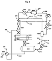
- the load to be treated arrives via line 201 in the exchanger E201, where it is heated by the regenerated liquid desiccant arriving via line 203. Leaving the exchanger E201 through line 202, the load enters the distillation device D201 , which successively overcomes from top to bottom a reboiling zone R201, a stripping zone S201 and a storage tank B201.
- the steam rising from the reboiling zone R201 is brought into countercurrent contact with a liquid phase composed mainly of stripping agent arriving via the conduit 210.
- the temperature in the reboiling zone R201 is generally between 150 ° C and 250 ° C.
- the absolute pressure in the assembly consisting of the distillation device D201, the reboiler R201, the stripping zone S201 and the flask B201 is generally between 0.5 and 2 bar.
- the reboiler R201 In the reboiler R201, most of the water and products lighter than the desiccant absorbed by the latter are vaporized.
- the water-depleted liquid desiccant falls by gravity from the reboiler R201 into the stripping zone S201, where it is brought into counter-current contact with the dehydrated stripping agent arriving in the flask B201 via the conduit 216.
- the regenerated liquid desiccant leaves the flask B201 through the conduit 203, passes through the exchanger E201, where it is cooled by the charge arriving through the conduit 201, and is evacuated from the process by the conduit 204.
- the water, the stripping agent and the other products vaporized in the reboiler R201 leave the distillation device D201 via the line 205, are mixed, if necessary, with the steam arriving from the flask B203 through the line 212, and cooled. in the condenser C201, from which they exit through the conduit 206 to enter the balloon B202.
- the lightest compounds are removed from the process in gaseous form via line 207; the water is removed from the process via line 208 with the other hydrophilic products; the stripping agent and the other hydrophobic products are sent, saturated with water, via the conduit 209 and through the pump P201, partly by the conduit 211 towards the exchanger E202, partly by the conduit 210 towards the zone of distillation D201 where it is brought into counter-current contact with the steam rising from the reboiling zone R201 through the distillation zone D201.
- the first part is partially vaporized in the exchanger E202 and sent through the conduit 217 to the balloon B203.
- the vapor phase generated in the exchanger E202 can be removed from the process. However, it is more advantageous to return it via line 212 upstream of the condenser C201 with the steam leaving the distillation device D201 through line 205.
- the liquid phase leaving the flask B203 via the line 213, leaner in water than the liquid arriving through the line 211, is divided so as to maintain constant the flow of stripping agent in the loop: a fixed part is sent to the 'E203 evaporator via line 215; any excess, due to the absorption by the desiccant of part of the gas stream treated during the dehydration step (not shown in the figure), is evacuated from the process by line 214.
- the vapor phase leaving the evaporator E203 via the duct 216 is sent to the balloon B201.
- Another modification of the process of the invention consists in carrying out the distillation and stripping steps simultaneously as shown in FIG. 3: the charge arrives via the conduit 301, the stripping agent is introduced, previously vaporized or not, directly into the reboiler R301 via the conduit 302, the distillation device D301 and the stripping zone S301 then being combined.
- the regenerated desiccant leaves the reboiler through line 304, while the vapor leaves the distillation device D301 through line 303.
- Another variant of the process of the invention consists in carrying out the stages of distillation, reboiling, stripping and condensation as shown in FIG. 4: the charge, after passing through the exchangers E401 and E402, is introduced through the conduit 401 in the distillation device D401, and falls by gravity into the reboiler R401.
- the vapor phase generated in the reboiler R401 rises the distillation device D401 then leaves the said device via the conduit 402.
- the partially regenerated desiccant is pumped from the reboiler R401, through the pump P401, and via the conduits 403 and 404, to the zone of stripping S401, which surmounts the storage tank B401.
- the regenerated desiccant leaves the flask B401 via the conduit 405, heats the charge in the exchanger E402 and is evacuated from the process by the conduit 415.
- the stripping agent and the stripped water leave the stripping zone S401 by the conduit 406 , are mixed, where appropriate, with the steam arriving from the flask B403 through the conduit 411, then cooled in the condenser C401 and separated in the flask B402, the light compounds of which exit in vapor form through the conduit 407, the water and any other hydrophilic products present are evacuated via line 408, the stripping agent and the other hydrophobic products possibly present are sent via line 409 and through the pump P402 to the exchanger E403, where a vapor phase V1 enriched with water and a liquid phase L1 depleted in water.
- the phases V1 and L1 are sent through the conduit 410 to the balloon B403; the vapor phase V1 leaves therefrom via the pipe 411 and is mixed with the steam leaving the stripping zone S401 through the pipe 406; the liquid phase L1 leaves the flask B403 via the conduit 416, then is divided into an excess part discharged from the process by the conduit 413 and a fixed part sent to the evaporator E404 via the conduit 412, vaporized and introduced into the reservoir balloon B401 via conduit 414.
- Another solution consists in reinjecting the stripping agent and the stripped water leaving S401 by 406 in the reboiler R401, and in condensing and separating them downstream from the distillation device D401, as in the previous diagrams ( Fig 1 to 3).
- the process according to the invention can be applied, for example, to the regeneration of a desiccant from the glycol family, such as monoethylene glycol (MEG), diethylene glycol (DEG), triethylene glycol (TEG) or tetraethylene glycol (T4EG); said desiccant can for example be used to dehydrate a natural gas or a refinery gas.
- a desiccant from the glycol family, such as monoethylene glycol (MEG), diethylene glycol (DEG), triethylene glycol (TEG) or tetraethylene glycol (T4EG)
- said desiccant can for example be used to dehydrate a natural gas or a refinery gas.
- the stripping agent can be, for example, a hydrocarbon or a mixture of hydrocarbons, and can in this case contain a significant proportion of aromatics and of benzene in particular.
- a particularly favorable case is that where the desiccant absorbs in the effluent to dehydrate products of a nature compatible with the stripping agent as defined in the present invention.
- the process is then in excess of stripping agent, which not only dispenses with any make-up but can be a source of profit.
- the load passes into the exchanger E1, with a power of 12.5 kW, from which it leaves via the conduit 2 at a temperature of 46 ° C., enters the exchanger E2, with a power of 259 kW, where it is reheated to the temperature of 146 ° C. by the regenerated TEG leaving the storage tank B1 via the pipe 4.
- the charge is introduced via the pipe 3 into the distillation device D1, which successively overcomes from top to bottom the reboiler R1, with a power of 177 kW, in which the temperature is 204 ° C, a stripping zone S1 and a storage tank B1 in which the partially regenerated TEG is brought into contact with counter-current with the stripping agent arriving in vapor form via line 16.
- the pressure in the distillation device D1 and in the reboiler R1 is 1.1 bar
- the pressure in the stripping zone S1 and in the flask -B1 tank is 1.2 bar.
- TEG regenerated TEG leaves the flask B1 through line 4 at a temperature of 194 ° C, heats in the exchanger E2 the load arriving from the exchanger E1 through line 2, and is evacuated from the process through line 5 at a flow rate of 3330 kg / h at a temperature of 84 ° C.
- Its mass composition is as follows: TEG 98.95% Water 33 ppm Benzene 1.03% Other hydrocarbons 144 ppm
- Water and stripping agent in vapor form leave the distillation device D1 via line 6 at a flow rate of 662 kg / h at the temperature of 114 ° C.
- the mass composition of this flow is as follows: Water 16.63% Benzene 79.39% Other hydrocarbons 3.68% TEG 0.30%
- This flow is then mixed with the steam arriving from the flask B3 through the conduit 12 at a flow rate of 163 kg / h at the temperature of 80 ° C., the mass composition of which is as follows: Water 0.57% Benzene 85.23% Other hydrocarbons 14.20%
- the mixture is cooled in the condenser C1, with a power of 175 kW, to a temperature of 40 ° C, at a pressure of 1 bar and sent through line 7 to the flask B2 from which three flows emerge: - the light hydrocarbons are evacuated from the process via line 8 at a flow rate of 8.7 kg / h, with the following mass composition: Water 3.08% Propanes 14.59% Benzene 42.00% Butanes 9.21% Methane 7.40% Pentanes 5.84% Ethane 15.49% Hexanes 2.39% the aqueous phase is removed from the process by line 9 at a flow rate of 112 kg / h, the mass composition of this flow is as follows: Water 98.05% Benzene 0.19% TEG 1.76% - the stripping agent is sent via line 10 and through pump P1 to exchanger E3, with a power of 34 kW, at a flow rate of 704 kg / h, the mass composition of this flow is as follows : Water
- the stripping agent enters the balloon B3. From there, steam is sent through line 12 upstream of condenser C1.
- the process used in this example made it possible to regenerate the desiccant (TEG) to a residual water content of less than 50 ppm.
- the residual water content of the stripping agent was divided by 8 by simple heating, by vaporizing less than a quarter of the desiccant agent in the exchanger E3, this although water is a product. heavier than the stripping agent which is mainly composed of benzene.
Landscapes
- Chemical & Material Sciences (AREA)
- Chemical Kinetics & Catalysis (AREA)
- Vaporization, Distillation, Condensation, Sublimation, And Cold Traps (AREA)
- Drying Of Gases (AREA)
- Electrical Discharge Machining, Electrochemical Machining, And Combined Machining (AREA)
- Organic Low-Molecular-Weight Compounds And Preparation Thereof (AREA)
Claims (13)
- Verfahren zur Regenerierung eines flüssigen Trocknungsmittels unter Verwendung eines Abstreifmittels, das bei Umgebungstemperatur und -druck flüssig ist und mit Wasser ein Heteroazeotrop bildet, wobei das verfahren die folgenden Schritte umfaßt:(a) einen Schritt des Aufkochens des flüssigen, mit Wasser beladenen Trocknungsmittels;(b) einen Schritt der Destillation des Trocknungsmittels, der wenigstens einen Schritt der Rektifizierung umfaßt;(c) einen Schritt des Abstreifens des während der Schritte (a) und (b) teilweise regenerierten, flüssigen Trocknungsmittels durch das verdampfte Abstreifmittel;(d) einen Schritt der Kondensation des den Schritt der Destillation (b) verlassenden Dampfes, wobei die Kondensation zwei flüssige Phasen erzeugt, einen Hauptteil aus Wasser, der andere Hauptteil aus Abstreifmittel;(e) das Aufheizen der an Abstreifmittel reichen flüssigen Phase aus dem Schritt (d), wobei das Erhitzen eine an Wasser reichere Dampfphase wie die flüssige Phase und eine an Wasser verarmte flüssige Phase erzeugt, und(f) das Zurückschicken der aus dem Schritt (e) stammenden flüssigen Phase zum Schritt (c).
- Verfahren nach Anspruch 1, dadurch gekennzeichnet, daß die während des Schrittes (e) erzeugte Dampfphase stromaufwärts vom Schritt (d) zurückgeschickt wird.
- Verfahren nach irgendeinem der Ansprüche 1 und 2, dadurch gekennzeichnet, daß die an Wasser verarmte, aus dem Schritt (d) stammende flüssige Phase teilweise zum Schritt (b) geschickt wird, wo sie im Gegenstrom mit dem Dampf der Destillation in Kontakt gebracht wird.
- Verfahren nach irgendeinem der Ansprüche 1 bis 3, dadurch gekennzeichnet, daß das dehydratisierte, aus dem Schritt (e) stammende Abstreifmittel verdampft wird, bevor es zum Schritt des Abstreifens (c) geschickt wird.
- Verfahren nach irgendeinem der Ansprüche 1 bis 3, dadurch gekennzeichnet, daß das dehydratisierte, aus dem Schritt (e) stammende Abstreifmittel in flüssiger Form zum Schritt des Abstreifens (c) geschickt und im Verlauf dessen verdampft wird.
- Verfahren nach irgendeinem der Ansprüche 1 bis 5, dadurch gekennzeichnet, daß die Schritte (b) und (c) in verschiedenen Vorrichtungen durchgeführt werden.
- Verfahren nach irgendeinem der Ansprüche 1 bis 5, dadurch gekennzeichnet, daß die Schritte (b) und (c) gleichzeitig in der gleichen Vorrichtung durchgeführt werden, wobei das Abstreifmittel in die Aufkochzone des Schrittes (a) eingeführt wird.
- Verfahren nach Anspruch 7, dadurch gekennzeichnet, daß das Abstreifmittel in die Aufkochzone in flüssiger Form eingeführt wird, wo es verdampft wird.
- Verfahren nach Anspruch 7, dadurch gekennzeichnet, daß das Abstreifmittel verdampft wird, bevor es in die Aufkochzone eingeführt wird.
- Verfahren nach irgendeinem der Ansprüche 1 bis 9, dadurch gekennzeichnet, daß das flüssige Trocknungsmittel ein Glykol ist.
- Verfahren nach Anspruch 10, dadurch gekennzeichnet, daß das flüssige Trocknungsmittel Triethylenglykol ist.
- Verfahren nach irgendeinem der Ansprüche 1 bis 11, dadurch gekennzeichnet, daß das Abstreifmittel eine Mischung von Kohlenwasserstoffen ist.
- Verfahren nach Anspruch 12, dadurch gekennzeichnet, daß das Abstreifmittel hauptsächlich Benzol enthält.
Applications Claiming Priority (2)
| Application Number | Priority Date | Filing Date | Title |
|---|---|---|---|
| FR9214020 | 1992-11-19 | ||
| FR9214020A FR2698017B1 (fr) | 1992-11-19 | 1992-11-19 | Procédé de régénération d'un dessicant liquide. |
Publications (2)
| Publication Number | Publication Date |
|---|---|
| EP0598657A1 EP0598657A1 (de) | 1994-05-25 |
| EP0598657B1 true EP0598657B1 (de) | 1996-06-12 |
Family
ID=9435779
Family Applications (1)
| Application Number | Title | Priority Date | Filing Date |
|---|---|---|---|
| EP93402779A Expired - Lifetime EP0598657B1 (de) | 1992-11-19 | 1993-11-16 | Verfahren zum Regenerieren von flüssigen Trocknungsmitteln |
Country Status (7)
| Country | Link |
|---|---|
| US (1) | US5501776A (de) |
| EP (1) | EP0598657B1 (de) |
| CA (1) | CA2103493C (de) |
| DE (1) | DE69303146T2 (de) |
| DK (1) | DK0598657T3 (de) |
| FR (1) | FR2698017B1 (de) |
| NO (1) | NO300088B1 (de) |
Cited By (1)
| Publication number | Priority date | Publication date | Assignee | Title |
|---|---|---|---|---|
| US11198091B2 (en) | 2018-10-26 | 2021-12-14 | Axens | Process for dehydrating a hydrocarbon-based gas |
Families Citing this family (8)
| Publication number | Priority date | Publication date | Assignee | Title |
|---|---|---|---|---|
| FR2725918B1 (fr) * | 1994-10-24 | 1996-12-20 | Technip Cie | Procede de sechage d'un gaz mettant en oeuvre la distillation d'un agent dessechant liquide |
| AUPS123202A0 (en) * | 2002-03-15 | 2002-04-18 | Australian Arrow Pty Ltd | Vehicle automatic emergency response system |
| US7867365B2 (en) * | 2003-03-28 | 2011-01-11 | Thermal Kinetics Systems, Llc | Ethanol distillation with distillers soluble solids recovery apparatus |
| FR2858247B1 (fr) * | 2003-07-30 | 2005-09-09 | Inst Francais Du Petrole | Procede de traitement de gaz par une solution de glycol filtree |
| US20080041228A1 (en) * | 2006-08-18 | 2008-02-21 | Brian Howard Seibert | Method of dehydration of gases with liquid desiccants |
| WO2008022426A1 (en) * | 2006-08-24 | 2008-02-28 | Brian Howard Seibert | Method of dehydration of gases with liquid desiccants |
| US8491712B2 (en) | 2010-09-13 | 2013-07-23 | General Electric Company | Dehydration systems and methods for removing water from a gas |
| WO2018165458A1 (en) | 2017-03-10 | 2018-09-13 | Compression Leasing Services, Inc. | Deep vacuum regeneration of adsorbent media |
Family Cites Families (19)
| Publication number | Priority date | Publication date | Assignee | Title |
|---|---|---|---|---|
| US1911829A (en) * | 1929-08-20 | 1933-05-30 | Standard Oil Dev Co | Process for producing dehydrated secondary alcohols |
| US2048178A (en) * | 1930-11-21 | 1936-07-21 | Shell Dev | Process for dehydrating organic compounds |
| US2750331A (en) * | 1954-07-28 | 1956-06-12 | Nat Tank Co | Desiccant reconcentrator |
| US3349544A (en) * | 1966-01-28 | 1967-10-31 | Dow Chemical Co | Gas drying process |
| US3471370A (en) * | 1966-04-20 | 1969-10-07 | Atlantic Richfield Co | Method for regenerating glycolamine absorbing solutions |
| US3370636A (en) * | 1967-02-03 | 1968-02-27 | Combustion Eng | Apparatus for reconcentrating liquid desiccant |
| US3397731A (en) * | 1968-02-07 | 1968-08-20 | Maloney Crawford Tank | Method and apparatus for reconcentrating liquid desiccant |
| US3975229A (en) * | 1970-02-12 | 1976-08-17 | Jackson Morden A | Flameless reboiler for reconcentrating liquid desiccant |
| DE2046050A1 (en) * | 1970-09-17 | 1972-03-23 | Maloney-Crawford Tank Corp., Tulsa, OkIa. (V.St.A.) | Fas drying liquid recovery method |
| US4009083A (en) * | 1971-09-02 | 1977-02-22 | The Dow Chemical Company | Regeneration of liquid desiccants and acid gas absorbing liquid desiccants |
| US4014667A (en) * | 1975-06-16 | 1977-03-29 | Phillips Petroleum Company | Antifreeze recovery system |
| US4021311A (en) * | 1975-09-12 | 1977-05-03 | Halcon International, Inc. | Recovery of alkylene glycols by azeotropic distillation with 1,2,3-trimethyl benzene |
| DE2649967B1 (de) * | 1976-10-30 | 1978-02-09 | Davy Powergas Gmbh | Verfahren zur rekonzentrierung eines wasserhaltigen glykols |
| DE2728745B1 (de) * | 1977-06-25 | 1978-10-26 | Davy Powergas Gmbh | Verfahren zur Rekonzentrierung von feuchtem Glykol |
| FR2490629A1 (fr) * | 1980-09-01 | 1982-03-26 | Inst Francais Du Petrole | Procede de production d'alcools deshydrates utilisables comme composant d'un carburant pour moteur |
| DE3038497C2 (de) * | 1980-10-11 | 1983-11-10 | Bayer Ag, 5090 Leverkusen | Verfahren und Vorrichtung zur Trennung von ein Azeotrop bildenden Gemischen |
| US4460383A (en) * | 1982-12-20 | 1984-07-17 | Black, Sivalls & Bryson | Method and apparatus for reconcentrating liquid absorbent |
| JPS59166205A (ja) * | 1983-03-10 | 1984-09-19 | Kao Corp | 有機溶媒から水を除去する方法 |
| US5035776A (en) * | 1990-03-29 | 1991-07-30 | University Of Massachusetts | Low energy extractive distillation process for producing anhydrous ethanol |
-
1992
- 1992-11-19 FR FR9214020A patent/FR2698017B1/fr not_active Expired - Fee Related
-
1993
- 1993-11-16 EP EP93402779A patent/EP0598657B1/de not_active Expired - Lifetime
- 1993-11-16 DE DE69303146T patent/DE69303146T2/de not_active Expired - Fee Related
- 1993-11-16 DK DK93402779.8T patent/DK0598657T3/da active
- 1993-11-17 NO NO934161A patent/NO300088B1/no unknown
- 1993-11-19 CA CA002103493A patent/CA2103493C/fr not_active Expired - Fee Related
- 1993-11-19 US US08/154,406 patent/US5501776A/en not_active Expired - Lifetime
Cited By (1)
| Publication number | Priority date | Publication date | Assignee | Title |
|---|---|---|---|---|
| US11198091B2 (en) | 2018-10-26 | 2021-12-14 | Axens | Process for dehydrating a hydrocarbon-based gas |
Also Published As
| Publication number | Publication date |
|---|---|
| NO300088B1 (no) | 1997-04-07 |
| FR2698017A1 (fr) | 1994-05-20 |
| NO934161D0 (no) | 1993-11-17 |
| US5501776A (en) | 1996-03-26 |
| FR2698017B1 (fr) | 1995-03-10 |
| NO934161L (no) | 1994-05-20 |
| CA2103493A1 (fr) | 1994-05-20 |
| DE69303146D1 (de) | 1996-07-18 |
| DE69303146T2 (de) | 1996-10-10 |
| CA2103493C (fr) | 2004-06-29 |
| EP0598657A1 (de) | 1994-05-25 |
| DK0598657T3 (da) | 1996-10-28 |
Similar Documents
| Publication | Publication Date | Title |
|---|---|---|
| EP0770667B1 (de) | Verfahren zur Trocknung von Gasen mittels Glycol mit anschliessender Raffinierung von gasförmigen Abflüssen | |
| EP0783031B1 (de) | Verfahren zur Entfernung von Wasser, Saüren und Benzin aus Erdgas, unter Verwendung eines Lösungsmittelgemisches | |
| EP1035904B1 (de) | Verfahren zur entwässerung eines feuchten gases mittels einer entwässerungsflüssigkeit, mit tiefregeneration der entwässerungsflüssigkeit | |
| CA1135518A (fr) | Procede perfectionne de production de froid et/ou de chaleur au moyen d'un cycle a absorption | |
| CA2357863C (fr) | Procede de pretraitement d'un gaz naturel contenant des gaz acides | |
| EP0796134B1 (de) | Verfahren zum behandeln von erdgas, das wasser und kondensierbare kohlenwasserstoffe enthält | |
| FR2814379A1 (fr) | Procede de desacidification d'un gaz par absorption dans un solvant avec un controle de la temperature | |
| EP0598657B1 (de) | Verfahren zum Regenerieren von flüssigen Trocknungsmitteln | |
| EP0768502A1 (de) | Verfahren und Vorrichtung zur Verflüssigung und Behandlung von Erdgas | |
| EP1072672B1 (de) | Verfahren und Vorrichtung zur Reinigung von Gasen | |
| FR2760653A1 (fr) | Procede de desacidification avec production de gaz acides en phase liquide | |
| EP0528709B2 (de) | Verfahren zum Zerlegen eines Gasgemisches mittels Absorption | |
| EP0768106B1 (de) | Verfahren zur Fraktionierung eines mehrere trennbare Komponenten enthaltenden Fluids wie z.B. Erdgas | |
| WO1995004116A1 (fr) | Procede de stabilisation des petroles bruts a la sortie du puits d'extraction et son dispositif de mise en ×uvre | |
| CA2214968C (fr) | Procede de deshydratation et de degazolinage d'un gaz, comportant un etage de refroidissement preliminaire | |
| EP3252408B1 (de) | Verfahren zur reinigung von erdgas und zur verflüssigung von kohlendioxid | |
| FR2725918A1 (fr) | Procede de sechage d'un gaz mettant en oeuvre la distillation d'un agent dessechant liquide | |
| CA1137768A (fr) | Etape de desorption des pompes a chaleur et machines frigorifiques a absorption | |
| BE438425A (de) | ||
| BE592154A (de) | ||
| BE509711A (de) | ||
| CH450390A (fr) | Procédé de fabrication du styrène |
Legal Events
| Date | Code | Title | Description |
|---|---|---|---|
| PUAI | Public reference made under article 153(3) epc to a published international application that has entered the european phase |
Free format text: ORIGINAL CODE: 0009012 |
|
| AK | Designated contracting states |
Kind code of ref document: A1 Designated state(s): DE DK GB IT NL |
|
| 17P | Request for examination filed |
Effective date: 19941125 |
|
| 17Q | First examination report despatched |
Effective date: 19950818 |
|
| GRAH | Despatch of communication of intention to grant a patent |
Free format text: ORIGINAL CODE: EPIDOS IGRA |
|
| ITF | It: translation for a ep patent filed |
Owner name: DE DOMINICIS & MAYER S.R.L. |
|
| GRAH | Despatch of communication of intention to grant a patent |
Free format text: ORIGINAL CODE: EPIDOS IGRA |
|
| GRAA | (expected) grant |
Free format text: ORIGINAL CODE: 0009210 |
|
| AK | Designated contracting states |
Kind code of ref document: B1 Designated state(s): DE DK GB IT NL |
|
| REF | Corresponds to: |
Ref document number: 69303146 Country of ref document: DE Date of ref document: 19960718 |
|
| GBT | Gb: translation of ep patent filed (gb section 77(6)(a)/1977) |
Effective date: 19960723 |
|
| REG | Reference to a national code |
Ref country code: DK Ref legal event code: T3 |
|
| PLBE | No opposition filed within time limit |
Free format text: ORIGINAL CODE: 0009261 |
|
| STAA | Information on the status of an ep patent application or granted ep patent |
Free format text: STATUS: NO OPPOSITION FILED WITHIN TIME LIMIT |
|
| 26N | No opposition filed | ||
| REG | Reference to a national code |
Ref country code: GB Ref legal event code: IF02 |
|
| PGFP | Annual fee paid to national office [announced via postgrant information from national office to epo] |
Ref country code: NL Payment date: 20071128 Year of fee payment: 15 Ref country code: DK Payment date: 20071127 Year of fee payment: 15 Ref country code: DE Payment date: 20071122 Year of fee payment: 15 |
|
| PGFP | Annual fee paid to national office [announced via postgrant information from national office to epo] |
Ref country code: IT Payment date: 20071121 Year of fee payment: 15 |
|
| PGFP | Annual fee paid to national office [announced via postgrant information from national office to epo] |
Ref country code: GB Payment date: 20071122 Year of fee payment: 15 |
|
| REG | Reference to a national code |
Ref country code: DK Ref legal event code: EBP |
|
| GBPC | Gb: european patent ceased through non-payment of renewal fee |
Effective date: 20081116 |
|
| PG25 | Lapsed in a contracting state [announced via postgrant information from national office to epo] |
Ref country code: NL Free format text: LAPSE BECAUSE OF NON-PAYMENT OF DUE FEES Effective date: 20090601 |
|
| NLV4 | Nl: lapsed or anulled due to non-payment of the annual fee |
Effective date: 20090601 |
|
| PG25 | Lapsed in a contracting state [announced via postgrant information from national office to epo] |
Ref country code: IT Free format text: LAPSE BECAUSE OF NON-PAYMENT OF DUE FEES Effective date: 20081116 |
|
| PG25 | Lapsed in a contracting state [announced via postgrant information from national office to epo] |
Ref country code: DK Free format text: LAPSE BECAUSE OF NON-PAYMENT OF DUE FEES Effective date: 20081130 Ref country code: DE Free format text: LAPSE BECAUSE OF NON-PAYMENT OF DUE FEES Effective date: 20090603 |
|
| PG25 | Lapsed in a contracting state [announced via postgrant information from national office to epo] |
Ref country code: GB Free format text: LAPSE BECAUSE OF NON-PAYMENT OF DUE FEES Effective date: 20081116 |