EP0598481A1 - Pressure control apparatus for an ink jet pen - Google Patents
Pressure control apparatus for an ink jet pen Download PDFInfo
- Publication number
- EP0598481A1 EP0598481A1 EP93307809A EP93307809A EP0598481A1 EP 0598481 A1 EP0598481 A1 EP 0598481A1 EP 93307809 A EP93307809 A EP 93307809A EP 93307809 A EP93307809 A EP 93307809A EP 0598481 A1 EP0598481 A1 EP 0598481A1
- Authority
- EP
- European Patent Office
- Prior art keywords
- ink
- orifice
- pen
- reservoir
- gap
- Prior art date
- Legal status (The legal status is an assumption and is not a legal conclusion. Google has not performed a legal analysis and makes no representation as to the accuracy of the status listed.)
- Granted
Links
- 239000007788 liquid Substances 0.000 claims abstract description 16
- 239000012530 fluid Substances 0.000 claims description 19
- 238000004891 communication Methods 0.000 claims description 7
- 230000000717 retained effect Effects 0.000 claims description 2
- 238000000034 method Methods 0.000 claims 1
- 239000012080 ambient air Substances 0.000 abstract description 9
- 230000007246 mechanism Effects 0.000 description 6
- 239000002657 fibrous material Substances 0.000 description 3
- 230000001105 regulatory effect Effects 0.000 description 3
- 239000003570 air Substances 0.000 description 2
- 230000008859 change Effects 0.000 description 2
- 238000001035 drying Methods 0.000 description 2
- 230000007613 environmental effect Effects 0.000 description 2
- 239000000463 material Substances 0.000 description 2
- 239000011148 porous material Substances 0.000 description 2
- 206010013642 Drooling Diseases 0.000 description 1
- 208000008630 Sialorrhea Diseases 0.000 description 1
- 230000004913 activation Effects 0.000 description 1
- 238000007792 addition Methods 0.000 description 1
- 238000013459 approach Methods 0.000 description 1
- 230000004888 barrier function Effects 0.000 description 1
- 239000011324 bead Substances 0.000 description 1
- 230000001276 controlling effect Effects 0.000 description 1
- 230000000779 depleting effect Effects 0.000 description 1
- 238000009792 diffusion process Methods 0.000 description 1
- 238000000605 extraction Methods 0.000 description 1
- 230000006872 improvement Effects 0.000 description 1
- 238000004519 manufacturing process Methods 0.000 description 1
- 230000005499 meniscus Effects 0.000 description 1
- 238000012986 modification Methods 0.000 description 1
- 230000004048 modification Effects 0.000 description 1
- 229920002492 poly(sulfone) Polymers 0.000 description 1
- 230000002035 prolonged effect Effects 0.000 description 1
- 230000004044 response Effects 0.000 description 1
- 238000004513 sizing Methods 0.000 description 1
- 229910001220 stainless steel Inorganic materials 0.000 description 1
- 239000010935 stainless steel Substances 0.000 description 1
- 238000006467 substitution reaction Methods 0.000 description 1
- 239000010409 thin film Substances 0.000 description 1
- 238000009834 vaporization Methods 0.000 description 1
- 230000008016 vaporization Effects 0.000 description 1
- XLYOFNOQVPJJNP-UHFFFAOYSA-N water Substances O XLYOFNOQVPJJNP-UHFFFAOYSA-N 0.000 description 1
Images


Classifications
-
- B—PERFORMING OPERATIONS; TRANSPORTING
- B41—PRINTING; LINING MACHINES; TYPEWRITERS; STAMPS
- B41J—TYPEWRITERS; SELECTIVE PRINTING MECHANISMS, i.e. MECHANISMS PRINTING OTHERWISE THAN FROM A FORME; CORRECTION OF TYPOGRAPHICAL ERRORS
- B41J2/00—Typewriters or selective printing mechanisms characterised by the printing or marking process for which they are designed
- B41J2/005—Typewriters or selective printing mechanisms characterised by the printing or marking process for which they are designed characterised by bringing liquid or particles selectively into contact with a printing material
- B41J2/01—Ink jet
- B41J2/17—Ink jet characterised by ink handling
- B41J2/175—Ink supply systems ; Circuit parts therefor
- B41J2/17503—Ink cartridges
- B41J2/17556—Means for regulating the pressure in the cartridge
-
- B—PERFORMING OPERATIONS; TRANSPORTING
- B41—PRINTING; LINING MACHINES; TYPEWRITERS; STAMPS
- B41J—TYPEWRITERS; SELECTIVE PRINTING MECHANISMS, i.e. MECHANISMS PRINTING OTHERWISE THAN FROM A FORME; CORRECTION OF TYPOGRAPHICAL ERRORS
- B41J2/00—Typewriters or selective printing mechanisms characterised by the printing or marking process for which they are designed
- B41J2/005—Typewriters or selective printing mechanisms characterised by the printing or marking process for which they are designed characterised by bringing liquid or particles selectively into contact with a printing material
- B41J2/01—Ink jet
- B41J2/17—Ink jet characterised by ink handling
- B41J2/175—Ink supply systems ; Circuit parts therefor
- B41J2/17503—Ink cartridges
- B41J2/17506—Refilling of the cartridge
-
- B—PERFORMING OPERATIONS; TRANSPORTING
- B41—PRINTING; LINING MACHINES; TYPEWRITERS; STAMPS
- B41J—TYPEWRITERS; SELECTIVE PRINTING MECHANISMS, i.e. MECHANISMS PRINTING OTHERWISE THAN FROM A FORME; CORRECTION OF TYPOGRAPHICAL ERRORS
- B41J2/00—Typewriters or selective printing mechanisms characterised by the printing or marking process for which they are designed
- B41J2/005—Typewriters or selective printing mechanisms characterised by the printing or marking process for which they are designed characterised by bringing liquid or particles selectively into contact with a printing material
- B41J2/01—Ink jet
- B41J2/17—Ink jet characterised by ink handling
- B41J2/175—Ink supply systems ; Circuit parts therefor
- B41J2/17503—Ink cartridges
- B41J2/17513—Inner structure
-
- B—PERFORMING OPERATIONS; TRANSPORTING
- B41—PRINTING; LINING MACHINES; TYPEWRITERS; STAMPS
- B41J—TYPEWRITERS; SELECTIVE PRINTING MECHANISMS, i.e. MECHANISMS PRINTING OTHERWISE THAN FROM A FORME; CORRECTION OF TYPOGRAPHICAL ERRORS
- B41J2/00—Typewriters or selective printing mechanisms characterised by the printing or marking process for which they are designed
- B41J2/005—Typewriters or selective printing mechanisms characterised by the printing or marking process for which they are designed characterised by bringing liquid or particles selectively into contact with a printing material
- B41J2/01—Ink jet
- B41J2/17—Ink jet characterised by ink handling
- B41J2/175—Ink supply systems ; Circuit parts therefor
- B41J2/17503—Ink cartridges
- B41J2/17553—Outer structure
Definitions
- the present invention relates to ink pens for ink-jet printers, and more particularly, to an apparatus for controlling the pressure within the reservoir of an ink pen.
- Ink-jet printers have become established as reliable and efficient printing devices.
- an ink-jet printer utilizes a print head which is moved relative to a printing surface.
- a control system activates the moving print head at the appropriate locations causing the print head to eject, or jet, ink drops onto the printing surface to form desired images and characters.
- Such printers typically include an ink pen which serves as a reservoir for storing ink and provides a means of supplying ink, as needed, to the print head.
- a print head using either system typically includes a plurality of orifices, each orifice having an associated chamber.
- ink is supplied via an inlet to the chamber.
- the ink is forced, or jetted, from the chamber through the orifice and onto the printing surface.
- thermal bubble type print heads the ink in the chamber is heated or vaporized, typically by a thin film resistor. The rapid expansion which results from vaporization of the ink forces a quantity of ink from the chamber through the orifice.
- piezoelectric type print heads a piezoelectric element creates a pressure wave within the chamber which ejects a quantity of ink through the orifice.
- both thermal bubble and piezoelectric print heads provide a reliable and efficient means of jetting ink from an orifice
- both types of print heads generally have no mechanism to prevent the free flow of ink through the orifice when the print head is not activated. If this occurs, ink may leak, or drool, uncontrollably onto the printing surface to produce an undesirable ink spot. In addition, leaking ink may build up on the print head and impair the proper operation of the print head.
- ink-jet printers supply ink from the ink pen to the print head at a slight underpressure or back pressure.
- a positive back pressure is used to refer to a pressure within an ink pen that is lower than the ambient pressure surrounding the print head orifice.
- the back pressure must be maintained within a desired operating range. That is, the back pressure must be large enough to prevent the unwanted free flow of ink through the orifice. At the same time, the back pressure must be small enough that the print head, when activated, can overcome the back pressure and eject the ink in a consistent and predictable manner. To meet these constraints and provide optimum operation of the ink-jet printer, a fairly constant and predictable back pressure should be maintained.
- the back pressure of an ink pen is affected by changes in either the ambient pressure or the internal pressure. For example, if an ink pen is subject to an increase in altitude, such as during transport aboard an aircraft, the ambient pressure may decrease substantially. Unless the back pressure of the ink pen increases accordingly, the ambient pressure level may drop below that of the back pressure and ink will likely leak from the print head. In addition, as ink is depleted from the ink pen reservoir the back pressure within the ink pen will tend to increase. Without some mechanism for compensating for this, the back pressure may exceed the operating range of the print head and the ink pen will become inoperative. Temperature variations may cause the ink and air within the ink pen to contract or expand, thereby affecting the back pressure. All of these factors must be accounted for in order to ensure consistent trouble-free operation of the ink-jet printer.
- the reservoir may be of a flexible material which can expand or contract.
- the reservoir may have sleeve and piston configuration or utilize an expandable bladder as an internal accumulator.
- the volume of ink within the reservoir varies due to depletion, thermal variations, or the like, the volume of the reservoir also varies.
- variable volume reservoirs use a resilient member, such as a spring, to constantly urge the reservoir toward an increased volume. In this manner, the desired back pressure is created.
- variable volume reservoirs inherently have maximum and minimum limitations on the size of the reservoir, they are typically least effective when the ink pen is either nearly full or nearly empty. For example, if a new ink pen with a variable volume reservoir is filled to capacity with ink, the reservoir is unable to further expand in response to back pressure changes. As a result, if the fluid volume within the reservoir expands due to a change in back pressure, a quantity of ink may be forced out through the print head. To compensate for this many new pens are not completely filled with ink. Even more significant, variable volume reservoirs typically have a minimum volume which is greater than zero. As the pen nears depletion and the reservoir shrinks to this minimum volume, further ink depletion raises the back pressure above the operating range of the print head. As a result, a quantity of unusable ink will remain in each discarded pen.
- a bubble generator is an orifice formed in the ink reservoir of an ink pen to allow fluid communication between the interior of the reservoir and the ambient atmosphere.
- the orifice is sized such that the capillarity of the ink normally retains a small quantity of ink in the orifice as a liquid seal.
- the geometry of the orifice is such that when the back pressure approaches the limit of the operating range of the print head the back pressure overcomes the capillarity of the ink and the liquid seal is broken. Ambient air then "bubbles" into the reservoir to reduce the back pressure. Ideally, when the back pressure drops, ink from the reservoir reenters the orifice and reinstates the liquid seal.
- the seal breaks and the orifice is not submerged, there is no ink to reinstate the seal and the back pressure may be lost.
- the ink level drops or the pen is oriented in such a manner that the orifice is above the ink level within the reservoir, the liquid seal may weaken and fail over time. This would permit the free flow of ambient air into the reservoir, eliminate the back pressure, and allow the ink pen to drool.
- an object of the present invention to provide an ink pen having a mechanism for maintaining a back pressure within the operating range of the print head.
- An ink pen in accordance with one aspect of the present invention has a reservoir for holding a supply of ink.
- the reservoir is provided with an orifice allowing fluid communication between the reservoir and a make up fluid, such as ambient atmosphere.
- a capillary member is positioned to retain a quantity of ink adjacent the orifice regardless of the pen orientation or ink level within the reservoir. The retained quantity of ink provides a liquid seal that seals the orifice and yet allows bubbles to pass through the seal to regulate the pressure within the reservoir.
- Figure 1 is a partially exploded, bottom, perspective view of an ink pen in accordance with one embodiment of the present invention.
- Figure 2 is bottom view of the ink pen of Figure 1.
- Figure 3 is a cross sectional view taken along line 3-3 in Figure 2.
- Figure 4 is a bottom view of the bubble generator and capillary member of the embodiment illustrated in Figure 1.
- Figure 5 is a side, cross sectional view of an alternative embodiment of a bubble generator and capillary member in accordance with the present invention.
- Figure 6 is a side view of the embodiment illustrated in Figure 5.
- FIG. 1 An ink pen in accordance with a preferred embodiment of the present invention is illustrated in Figure 1 as reference numeral 10.
- the ink pen 10 has a reservoir 12 for storing a supply of ink 14.
- the reservoir is in fluid communication with a print head 16 which ejects ink drops onto a printing surface to form characters and images.
- the ink within the reservoir is subject to an initial back pressure to prevent the ink from drooling through the print head.
- the reservoir 12 is provided with a bubble generator 18 which allows fluid communication between the interior of the reservoir and a make up fluid, such as, the ambient atmosphere.
- a make up fluid such as, the ambient atmosphere.
- the bubble generator is sealed with a quantity of ink.
- the back pressure overcomes the capillary forces of the liquid seal and allows the make up fluid, ambient air in the illustrated embodiments, to bubble into the reservoir to reduce the back pressure.
- the liquid seal reforms to prevent further ingress of the make up fluid.
- the bubble generator 18 consists of a tubular boss 22 and a sphere 24 mounted concentrically within the boss.
- the outside diameter of the sphere 24 is smaller than the inside diameter of the boss 22 to define an annular orifice 20 (seen in Figure 4).
- the sphere is maintained within the boss by a number of raised crush ribs 26 formed around the interior of the boss. In this manner the sphere 24 can be easily press fit into the boss 22 and firmly maintained in position by the crush ribs 26. Additional raised ribs 28 are also provided to help maintain the sphere in position away from the inside wall of the boss.
- the sphere 24 serves as a capillary member to maintain a quantity of ink within the boss 22.
- a quantity of ink is trapped within the boss. Due to the curved surface of the sphere, the gap between the exterior surface of the sphere and the inner wall of the boss is smallest at the orifice and increases as the distance from the orifice increases.
- This geometry coupled with the capillarity of the ink, constantly urges the trapped quantity of ink toward the orifice--the smallest portion of the gap--to provide a robust seal.
- the bubble generator is provided with an inlet labyrinth 30 which serves as a vapor barrier.
- the inlet labyrinth is a path through which the ambient air must travel before contacting the trapped ink.
- the proximal end 31 of the labyrinth opens to the boss and the distal end 33 opens to ambient air.
- the length of the labyrinth is sealed from both the ambient and the reservoir.
- the humidity within the labyrinth varies along its length from approximately 100% at the proximal end 31 to approximately ambient at the distal end 33. This humidity gradient serves to shield the trapped ink from direct contact with ambient air and prevent the trapped ink from drying or solidifying.
- the inlet labyrinth is a path having a semi-circular cross section.
- the ratio of the cross sectional area to length of the inlet labyrinth should be such that the volume of air in the inlet labyrinth effectively blocks convective mass transfer.
- Diffusive vapor losses are driven by the partial pressure gradients through the inlet labyrinth. As indicated by Fick's Laws of Diffusion, these losses are proportional to the cross sectional area of the inlet labyrinth and inversely proportional to the length of the inlet labyrinth.
- the appropriate dimensions of an inlet labyrinth for any particular embodiment can be empirically determined by one skilled in the art.
- the inlet labyrinth in the illustrated embodiment is a trough 32 molded directly into the external surface of the reservoir 12.
- a cover 34 is attached to the reservoir to seal the trough 32 between its ends.
- a hole 36 through the cover at the distal end 33 of the trough 32 provides fluid communication between the trough and the ambient atmosphere.
- the circuitous configuration of the trough conserves space and reduces the size of the cover.
- the inlet labyrinth 30 also serves as an overflow receptacle. If the pen is subject to an environmental change, such as a temperature or altitude variation, which causes the fluid volume within the reservoir to expand beyond the capacity of the reservoir, the excess ink can exit the reservoir via the bubble generator and enter the inlet labyrinth 30. Subsequently, when the environmental conditions return to normal, or ink is depleted from the reservoir, the excess ink can reenter the reservoir.
- an environmental change such as a temperature or altitude variation
- the largest cross-sectional dimension of the labyrinth is small enough to allow the ink to form a complete meniscus across the cross section at any location along the labyrinth. Otherwise, small amounts or beads of ink may become stranded in the labyrinth.
- the maximum cross-sectional dimension of the labyrinth is approximately 0.89 mm.
- the effectiveness of the illustrated ink pen depends on the appropriate sizing of the orifice 20, the boss 22, and the sphere 24 to ensure that the liquid seal gives way below the maximum allowable back pressure and is reinstated above the minimum allowable back pressure.
- the exact dimensions of the various elements of the ink pen will depend on a number of factors, such as the surface energies of the materials, the density and surface tension of the ink, the desired range of back pressures, and the shape of the orifice. Once these factors are known, the proper dimensions can be readily calculated or empirically determined by one skilled in the art.
- the desired range of back pressures is from 10 cm to 16 cm water column and the ink used has a density of approximately 1 g/cm3 and a surface tension of approximately 60.2 dynes/cm.
- a stainless steel sphere having a diameter of approximately 3.18 mm and a polysulfone boss having an inside diameter of between 3.34 mm and 3.39 mm have been found to be satisfactory.
- each particular embodiment of the invention may require different dimensions according to its particular parameters.
- a bubble generator in accordance with an alternative embodiment of the invention, illustrated in Figures 5 and 6, has a base plate 40 which is attached to the inside of an ink pen reservoir 12.
- the base plate 40 is provided with an arched trough 42 and a recess 46.
- a cover plate 44 fits within the recess 46 to cover the trough 42.
- the cover plate 44 has an orifice 48 directly over the peak of the arched trough.
- One end of the trough is open to the ink within the interior of the reservoir and the other end is vented via opening 50 to the ambient atmosphere.
- the ink is drawn, by capillary forces, into the trough to form a liquid seal under the orifice 48.
- the ink pen Regardless of the orientation of the ink pen, a quantity of ink is trapped within the trough by capillary forces.
- the cross sectional area of the trough is at a minimum at the peak of the arch adjacent the orifice.
- This geometry in combination with capillarity of the ink, urges the trapped ink toward the peak of the arch and, hence, the orifice to maintain a strong and robust seal.
- the trough is sized such that when the back pressure exceeds the working range of the print head, the ambient air pushes the liquid seal up the trough, and allows ambient air to bubble through the orifice into the reservoir to lower the back pressure. As the back pressure returns to the desired range, the capillarity of the ink causes it to move into the trough to reseal the orifice.
- curved capillary members such as a sphere or an arched trough, are used to urge a quantity of ink toward an orifice.
- the capillary member need not be curved.
- a cylinder concentrically mounted within a boss or a flat trough could also serve to trap a quantity of ink adjacent an orifice.
- a fibrous or porous material 53 forms an ink path between the bubble generator and the capillary reservoir 57.
- the purpose of the fibrous or porous material is to prevent the bubble generator make up fluid, entering through orifii 52 and 54 from escaping into the capillary reservoir 57 and depleting the supply of ink in the capillary reservoir 57.
- Orifice 54 is sized such that the capillary forces in the orifice 54 are stronger than those in the capillary reservoir 57 and draw liquid from the reservoir, through the fibrous material to replenish the seal.
- the appropriate sizes for the orifii and capillary reservoir can be determined by one skilled in the art.
Landscapes
- Ink Jet (AREA)
Abstract
Description
- The present invention relates to ink pens for ink-jet printers, and more particularly, to an apparatus for controlling the pressure within the reservoir of an ink pen.
- Ink-jet printers have become established as reliable and efficient printing devices. Typically, an ink-jet printer, utilizes a print head which is moved relative to a printing surface. A control system activates the moving print head at the appropriate locations causing the print head to eject, or jet, ink drops onto the printing surface to form desired images and characters. Such printers typically include an ink pen which serves as a reservoir for storing ink and provides a means of supplying ink, as needed, to the print head.
- There are two commonly used systems for ejecting ink from a print head. The first is a thermal bubble system and the second is a piezoelectric system. A print head using either system typically includes a plurality of orifices, each orifice having an associated chamber. In operation, ink is supplied via an inlet to the chamber. Upon activation, the ink is forced, or jetted, from the chamber through the orifice and onto the printing surface. In thermal bubble type print heads, the ink in the chamber is heated or vaporized, typically by a thin film resistor. The rapid expansion which results from vaporization of the ink forces a quantity of ink from the chamber through the orifice. In piezoelectric type print heads, a piezoelectric element creates a pressure wave within the chamber which ejects a quantity of ink through the orifice.
- Although both thermal bubble and piezoelectric print heads provide a reliable and efficient means of jetting ink from an orifice, both types of print heads generally have no mechanism to prevent the free flow of ink through the orifice when the print head is not activated. If this occurs, ink may leak, or drool, uncontrollably onto the printing surface to produce an undesirable ink spot. In addition, leaking ink may build up on the print head and impair the proper operation of the print head.
- To alleviate these problems, many ink-jet printers supply ink from the ink pen to the print head at a slight underpressure or back pressure. As used herein a positive back pressure is used to refer to a pressure within an ink pen that is lower than the ambient pressure surrounding the print head orifice.
- To be effective, the back pressure must be maintained within a desired operating range. That is, the back pressure must be large enough to prevent the unwanted free flow of ink through the orifice. At the same time, the back pressure must be small enough that the print head, when activated, can overcome the back pressure and eject the ink in a consistent and predictable manner. To meet these constraints and provide optimum operation of the ink-jet printer, a fairly constant and predictable back pressure should be maintained.
- The back pressure of an ink pen is affected by changes in either the ambient pressure or the internal pressure. For example, if an ink pen is subject to an increase in altitude, such as during transport aboard an aircraft, the ambient pressure may decrease substantially. Unless the back pressure of the ink pen increases accordingly, the ambient pressure level may drop below that of the back pressure and ink will likely leak from the print head. In addition, as ink is depleted from the ink pen reservoir the back pressure within the ink pen will tend to increase. Without some mechanism for compensating for this, the back pressure may exceed the operating range of the print head and the ink pen will become inoperative. Temperature variations may cause the ink and air within the ink pen to contract or expand, thereby affecting the back pressure. All of these factors must be accounted for in order to ensure consistent trouble-free operation of the ink-jet printer.
- One type of ink pen uses a variable volume reservoir to solve these problems. For example, the reservoir may be of a flexible material which can expand or contract. Alternatively, the reservoir may have sleeve and piston configuration or utilize an expandable bladder as an internal accumulator. In this type of ink pen, as the volume of ink within the reservoir varies due to depletion, thermal variations, or the like, the volume of the reservoir also varies. Although a significant improvement over previous ink pens, such devices suffer from certain drawbacks.
- For example, such devices do not necessarily provide a constant back pressure. Rather, a reservoir with a freely variable volume will tend to maintain an internal reservoir pressure which is equal to the ambient pressure, that is, zero back pressure. To overcome this problem, many variable volume reservoirs use a resilient member, such as a spring, to constantly urge the reservoir toward an increased volume. In this manner, the desired back pressure is created.
- Because variable volume reservoirs inherently have maximum and minimum limitations on the size of the reservoir, they are typically least effective when the ink pen is either nearly full or nearly empty. For example, if a new ink pen with a variable volume reservoir is filled to capacity with ink, the reservoir is unable to further expand in response to back pressure changes. As a result, if the fluid volume within the reservoir expands due to a change in back pressure, a quantity of ink may be forced out through the print head. To compensate for this many new pens are not completely filled with ink. Even more significant, variable volume reservoirs typically have a minimum volume which is greater than zero. As the pen nears depletion and the reservoir shrinks to this minimum volume, further ink depletion raises the back pressure above the operating range of the print head. As a result, a quantity of unusable ink will remain in each discarded pen.
- To reduce this problem, some ink pens incorporate a "bubble generator." A bubble generator is an orifice formed in the ink reservoir of an ink pen to allow fluid communication between the interior of the reservoir and the ambient atmosphere. The orifice is sized such that the capillarity of the ink normally retains a small quantity of ink in the orifice as a liquid seal. The geometry of the orifice is such that when the back pressure approaches the limit of the operating range of the print head the back pressure overcomes the capillarity of the ink and the liquid seal is broken. Ambient air then "bubbles" into the reservoir to reduce the back pressure. Ideally, when the back pressure drops, ink from the reservoir reenters the orifice and reinstates the liquid seal.
- However, if the seal breaks and the orifice is not submerged, there is no ink to reinstate the seal and the back pressure may be lost. In addition, if the ink level drops or the pen is oriented in such a manner that the orifice is above the ink level within the reservoir, the liquid seal may weaken and fail over time. This would permit the free flow of ambient air into the reservoir, eliminate the back pressure, and allow the ink pen to drool.
- Accordingly, it is an object of the present invention to provide an ink pen having a mechanism for maintaining a back pressure within the operating range of the print head.
- It is a further object of the invention to provide a mechanism for regulating the pressure in an ink pen that allows for the efficient extraction of ink from the pen and minimizes the amount of unusable ink which is discarded with an ink pen that stops printing because the back pressure exceeded the operating range.
- It is another object of the invention to provide a mechanism for regulating the pressure in an ink pen that operates reliably and consistently regardless of pen orientation.
- It is a further object of the invention to provide a pressure regulating mechanism for an ink pen that is easy and inexpensive to manufacture and has few complicated parts.
- An ink pen in accordance with one aspect of the present invention has a reservoir for holding a supply of ink. The reservoir is provided with an orifice allowing fluid communication between the reservoir and a make up fluid, such as ambient atmosphere. A capillary member is positioned to retain a quantity of ink adjacent the orifice regardless of the pen orientation or ink level within the reservoir. The retained quantity of ink provides a liquid seal that seals the orifice and yet allows bubbles to pass through the seal to regulate the pressure within the reservoir.
- Other objects and aspects of the invention will become apparent to those skilled in the art from the detailed description of the invention which is presented by way of example and not as a limitation of the present invention.
- Figure 1 is a partially exploded, bottom, perspective view of an ink pen in accordance with one embodiment of the present invention.
- Figure 2 is bottom view of the ink pen of Figure 1.
- Figure 3 is a cross sectional view taken along line 3-3 in Figure 2.
- Figure 4 is a bottom view of the bubble generator and capillary member of the embodiment illustrated in Figure 1.
- Figure 5 is a side, cross sectional view of an alternative embodiment of a bubble generator and capillary member in accordance with the present invention.
- Figure 6 is a side view of the embodiment illustrated in Figure 5.
- An ink pen in accordance with a preferred embodiment of the present invention is illustrated in Figure 1 as
reference numeral 10. Theink pen 10 has areservoir 12 for storing a supply ofink 14. The reservoir is in fluid communication with aprint head 16 which ejects ink drops onto a printing surface to form characters and images. The ink within the reservoir is subject to an initial back pressure to prevent the ink from drooling through the print head. - To maintain the back pressure within a desired range, the
reservoir 12 is provided with abubble generator 18 which allows fluid communication between the interior of the reservoir and a make up fluid, such as, the ambient atmosphere. When the back pressure is within the desired range the bubble generator is sealed with a quantity of ink. However, when the back pressure exceeds the desired range, the back pressure overcomes the capillary forces of the liquid seal and allows the make up fluid, ambient air in the illustrated embodiments, to bubble into the reservoir to reduce the back pressure. When the back pressure returns to the appropriate level, the liquid seal reforms to prevent further ingress of the make up fluid. - As illustrated in Figure 3, the
bubble generator 18 consists of atubular boss 22 and asphere 24 mounted concentrically within the boss. The outside diameter of thesphere 24 is smaller than the inside diameter of theboss 22 to define an annular orifice 20 (seen in Figure 4). In the illustrated embodiment, the sphere is maintained within the boss by a number of raisedcrush ribs 26 formed around the interior of the boss. In this manner thesphere 24 can be easily press fit into theboss 22 and firmly maintained in position by thecrush ribs 26. Additional raisedribs 28 are also provided to help maintain the sphere in position away from the inside wall of the boss. In an alternative, and preferred embodiment, there are six raised ribs and no crush ribs. The raised ribs are sized to provide the necessary interference for a press fit to maintain the sphere within the boss and provide the necessary clearance from the inside wall of the boss. - The
sphere 24 serves as a capillary member to maintain a quantity of ink within theboss 22. As a result, even when the pen is oriented such that the boss is not submerged in the reservoir ink, a quantity of ink is trapped within the boss. Due to the curved surface of the sphere, the gap between the exterior surface of the sphere and the inner wall of the boss is smallest at the orifice and increases as the distance from the orifice increases. This geometry, coupled with the capillarity of the ink, constantly urges the trapped quantity of ink toward the orifice--the smallest portion of the gap--to provide a robust seal. - To prevent the trapped quantity of ink from drying or solidifying as a result of prolonged exposure to the atmosphere, the bubble generator is provided with an
inlet labyrinth 30 which serves as a vapor barrier. The inlet labyrinth, best seen in Figures 1 and 2, is a path through which the ambient air must travel before contacting the trapped ink. Theproximal end 31 of the labyrinth opens to the boss and thedistal end 33 opens to ambient air. The length of the labyrinth is sealed from both the ambient and the reservoir. As a result, the humidity within the labyrinth varies along its length from approximately 100% at theproximal end 31 to approximately ambient at thedistal end 33. This humidity gradient serves to shield the trapped ink from direct contact with ambient air and prevent the trapped ink from drying or solidifying. - The inlet labyrinth is a path having a semi-circular cross section. The ratio of the cross sectional area to length of the inlet labyrinth should be such that the volume of air in the inlet labyrinth effectively blocks convective mass transfer. Diffusive vapor losses are driven by the partial pressure gradients through the inlet labyrinth. As indicated by Fick's Laws of Diffusion, these losses are proportional to the cross sectional area of the inlet labyrinth and inversely proportional to the length of the inlet labyrinth. The appropriate dimensions of an inlet labyrinth for any particular embodiment can be empirically determined by one skilled in the art.
- As seen in Figures 2, and 3, the inlet labyrinth in the illustrated embodiment, is a
trough 32 molded directly into the external surface of thereservoir 12. Acover 34 is attached to the reservoir to seal thetrough 32 between its ends. Ahole 36 through the cover at thedistal end 33 of thetrough 32 provides fluid communication between the trough and the ambient atmosphere. The circuitous configuration of the trough conserves space and reduces the size of the cover. - The
inlet labyrinth 30 also serves as an overflow receptacle. If the pen is subject to an environmental change, such as a temperature or altitude variation, which causes the fluid volume within the reservoir to expand beyond the capacity of the reservoir, the excess ink can exit the reservoir via the bubble generator and enter theinlet labyrinth 30. Subsequently, when the environmental conditions return to normal, or ink is depleted from the reservoir, the excess ink can reenter the reservoir. - To ensure that excess ink in the labyrinth will completely reenter the reservoir, it is preferable that the largest cross-sectional dimension of the labyrinth is small enough to allow the ink to form a complete meniscus across the cross section at any location along the labyrinth. Otherwise, small amounts or beads of ink may become stranded in the labyrinth. In the illustrated embodiment, the maximum cross-sectional dimension of the labyrinth is approximately 0.89 mm.
- The effectiveness of the illustrated ink pen depends on the appropriate sizing of the
orifice 20, theboss 22, and thesphere 24 to ensure that the liquid seal gives way below the maximum allowable back pressure and is reinstated above the minimum allowable back pressure. The exact dimensions of the various elements of the ink pen will depend on a number of factors, such as the surface energies of the materials, the density and surface tension of the ink, the desired range of back pressures, and the shape of the orifice. Once these factors are known, the proper dimensions can be readily calculated or empirically determined by one skilled in the art. - In the illustrated embodiment, the desired range of back pressures is from 10 cm to 16 cm water column and the ink used has a density of approximately 1 g/cm³ and a surface tension of approximately 60.2 dynes/cm. A stainless steel sphere having a diameter of approximately 3.18 mm and a polysulfone boss having an inside diameter of between 3.34 mm and 3.39 mm have been found to be satisfactory. Of course, each particular embodiment of the invention may require different dimensions according to its particular parameters.
- A bubble generator in accordance with an alternative embodiment of the invention, illustrated in Figures 5 and 6, has a
base plate 40 which is attached to the inside of anink pen reservoir 12. Thebase plate 40 is provided with anarched trough 42 and arecess 46. Acover plate 44 fits within therecess 46 to cover thetrough 42. Thecover plate 44 has anorifice 48 directly over the peak of the arched trough. One end of the trough is open to the ink within the interior of the reservoir and the other end is vented via opening 50 to the ambient atmosphere. As a result, the ink is drawn, by capillary forces, into the trough to form a liquid seal under theorifice 48. - Regardless of the orientation of the ink pen, a quantity of ink is trapped within the trough by capillary forces. As a result of the arched shape of the trough, the cross sectional area of the trough is at a minimum at the peak of the arch adjacent the orifice. This geometry, in combination with capillarity of the ink, urges the trapped ink toward the peak of the arch and, hence, the orifice to maintain a strong and robust seal. The trough is sized such that when the back pressure exceeds the working range of the print head, the ambient air pushes the liquid seal up the trough, and allows ambient air to bubble through the orifice into the reservoir to lower the back pressure. As the back pressure returns to the desired range, the capillarity of the ink causes it to move into the trough to reseal the orifice.
- In the illustrated embodiments, curved capillary members, such as a sphere or an arched trough, are used to urge a quantity of ink toward an orifice. However, in other embodiments the capillary member need not be curved. For example, a cylinder concentrically mounted within a boss or a flat trough could also serve to trap a quantity of ink adjacent an orifice.
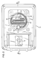
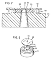
- In yet another embodiment, shown in Figures 7 and 8, a fibrous or
porous material 53 forms an ink path between the bubble generator and thecapillary reservoir 57. The purpose of the fibrous or porous material is to prevent the bubble generator make up fluid, entering throughorifii capillary reservoir 57 and depleting the supply of ink in thecapillary reservoir 57.Orifice 54 is sized such that the capillary forces in theorifice 54 are stronger than those in thecapillary reservoir 57 and draw liquid from the reservoir, through the fibrous material to replenish the seal. The appropriate sizes for the orifii and capillary reservoir can be determined by one skilled in the art. - This detailed description is set forth only for purposes of illustrating examples of the present invention and should not be considered to limit the scope thereof in any way. Clearly, numerous additions, substitutions, and other modifications can be made to the invention without departing from the scope of the invention which is defined in the appended claims and equivalents thereof.
Claims (10)
- A pen for an ink-jet printer comprising:
a reservoir (12) for holding ink (14) and having an orifice (20) formed therein to allow fluid communication between the interior of said reservoir and a volume of make up fluid;
a capillary member (24) positioned adjacent said orifice, said capillary member being structured to retain a quantity of liquid adjacent said orifice, whereby a portion of said quantity of liquid is drawn into said orifice to seal the orifice. - The pen of claim 1 further comprising a means (30) for preventing exposure of said quantity of liquid to ambient humidity.
- The pen of claim 1 further comprising a chamber (30) for holding a volume of make up fluid, said chamber being in fluid communication with the orifice and with ambient atmosphere.
- The pen of claim 1 further comprising an inlet labyrinth (30) having a proximal end adjacent said orifice (20), a mid portion, and a distal end open to ambient, said mid portion being dimensioned to create a humidity gradient between the proximal and distal ends.
- The pen of claim 1 wherein the capillary member (24) is positioned to define a gap between the capillary member and the reservoir, wherein said gap is sized such that the capillarity of the ink retains a quantity of ink within said gap.
- The pen of claim 5 wherein the size of the gap varies in relation to the distance from the orifice (20) such that capillary forces urge the retained quantity of ink toward the orifice.
- The pen of claims 1 or 6 wherein the capillary member is a plate (42).
- The pen of claim 7 wherein the plate (42) has a curved surface.
- The pen of claims 1 or 6 wherein the capillary member is a sphere (24).
- A method of forming a pressure sensitive seal at an orifice in an ink reservoir of an ink pen comprising the steps of:
forming a gap adjacent said orifice; and
submerging the gap in a fluid, said gap being sized such that when submerged, a quantity of fluid becomes trapped in the gap;
guiding the trapped quantity of fluid into the orifice to form a pressure sensitive seal.
Applications Claiming Priority (2)
| Application Number | Priority Date | Filing Date | Title |
|---|---|---|---|
| US957534 | 1992-10-05 | ||
| US07/957,534 US5526030A (en) | 1992-10-05 | 1992-10-05 | Pressure control apparatus for an ink pen |
Publications (2)
| Publication Number | Publication Date |
|---|---|
| EP0598481A1 true EP0598481A1 (en) | 1994-05-25 |
| EP0598481B1 EP0598481B1 (en) | 1996-12-04 |
Family
ID=25499722
Family Applications (1)
| Application Number | Title | Priority Date | Filing Date |
|---|---|---|---|
| EP93307809A Expired - Lifetime EP0598481B1 (en) | 1992-10-05 | 1993-09-30 | Pressure control apparatus for an ink jet pen |
Country Status (5)
| Country | Link |
|---|---|
| US (1) | US5526030A (en) |
| EP (1) | EP0598481B1 (en) |
| JP (1) | JP3406027B2 (en) |
| DE (1) | DE69306366T2 (en) |
| HK (1) | HK91697A (en) |
Cited By (14)
| Publication number | Priority date | Publication date | Assignee | Title |
|---|---|---|---|---|
| DE19534578A1 (en) * | 1994-09-16 | 1996-03-28 | Seiko Epson Corp | Ink tank cartridge for ink jet printer |
| DE19534613A1 (en) * | 1994-09-16 | 1996-03-28 | Seiko Epson Corp | Ink jet printers, ink cartridges for ink jet printers, and ink delivery system and method |
| FR2731652A1 (en) * | 1995-03-13 | 1996-09-20 | Seiko Epson Corp | INK JET PRINT UNIT STORAGE BOX |
| EP0803365A2 (en) * | 1996-04-26 | 1997-10-29 | Pelikan Produktions Ag | An ink cartridge for a printer |
| US6145974A (en) * | 1983-10-13 | 2000-11-14 | Seiko Epson Corporation | Ink-supplied printer head and ink container |
| EP1084848A1 (en) | 1999-09-14 | 2001-03-21 | Firma Artech GmbH, design + production in plastic | Assembly for forming a ventilation opening |
| US6247803B1 (en) | 1983-10-13 | 2001-06-19 | Seiko Epson Corporation | Ink jet recording apparatus and method for replenishing ink in the tank cartridge |
| US6276785B1 (en) | 1983-10-13 | 2001-08-21 | Seiko Epson Corporation | Ink-supplied printer head and ink container |
| DE19549524B4 (en) * | 1994-09-16 | 2004-11-25 | Seiko Epson Corp. | Ink tank cartridge for ink jet printer - has ink supply port extending through wall of second chamber to supply ink to exterior of cartridge and funnel shaped packing member related to inlet port |
| US6854835B2 (en) | 1994-09-16 | 2005-02-15 | Seiko Epson Corporation | Ink cartridge for ink jet printer and method of charging ink into said cartridge |
| WO2005077659A1 (en) * | 2004-01-19 | 2005-08-25 | Ninestar Image Co. Ltd. | Ink cartridge for an ink-jet printer |
| DE19549529B4 (en) * | 1994-09-16 | 2005-12-01 | Seiko Epson Corp. | Ink tank cartridge for ink jet printer - has ink supply port extending through wall of second chamber to supply ink to exterior of cartridge and funnel shaped packing member related to inlet port |
| DE19549778B4 (en) * | 1994-09-16 | 2006-03-09 | Seiko Epson Corp. | Ink tank cartridge for ink jet printer - has ink supply port extending through wall of second chamber to supply ink to exterior of cartridge and funnel shaped packing member related to inlet port |
| WO2007050172A1 (en) * | 2005-10-28 | 2007-05-03 | Hewlett-Packard Development Company, L.P. | Fluid delivery system for printing device |
Families Citing this family (48)
| Publication number | Priority date | Publication date | Assignee | Title |
|---|---|---|---|---|
| US6474798B1 (en) | 1984-10-11 | 2002-11-05 | Seiko Epson Corporation | Ink supplied printer head and ink container |
| US5600358A (en) * | 1993-06-30 | 1997-02-04 | Hewlett-Packard Company | Ink pen having a hydrophobic barrier for controlling ink leakage |
| US6280024B1 (en) | 1993-11-05 | 2001-08-28 | Seiko Epson Corporation | Ink cartridge for printer |
| USD379637S (en) * | 1995-02-23 | 1997-06-03 | Seiko Epson Corporation | Print head of ink jet printer |
| USD387379S (en) * | 1996-03-29 | 1997-12-09 | Canon Kabushiki Kaisha | Ink tank for printer |
| USD387087S (en) * | 1996-03-29 | 1997-12-02 | Canon Kabushiki Kaisha | Ink tank for printer |
| US5933175A (en) * | 1996-08-05 | 1999-08-03 | Hewlett-Packard Company | Bottom fill inkjet cartridge through bubble generator |
| USD424103S (en) * | 1999-02-18 | 2000-05-02 | Hewlett-Packard Company | Inkjet printhead |
| US5988803A (en) * | 1997-12-12 | 1999-11-23 | Lexmark International, Inc. | Ink leakage control arrangement for an ink cartridge |
| US6158848A (en) * | 1997-12-31 | 2000-12-12 | Liu; Win-Yin | Refilling device for ink cartridge of a jet printer |
| US6019459A (en) * | 1998-09-10 | 2000-02-01 | Hewlett-Packard Company | Dual capillarity ink accumulator for ink-jet |
| CN1089296C (en) * | 1998-10-30 | 2002-08-21 | 财团法人工业技术研究院 | Pressure controller |
| TW492001B (en) * | 1998-12-21 | 2002-06-21 | Ind Tech Res Inst | Double focused optical read/write head |
| CN1096359C (en) * | 1999-03-26 | 2002-12-18 | 财团法人工业技术研究院 | Ink pressure cotnrol device for ink jet box |
| USD430897S (en) * | 1999-06-11 | 2000-09-12 | Lexmark International, Inc. | Ink cartridge for printer |
| US6540341B2 (en) | 2000-01-29 | 2003-04-01 | Industrial Technology Research Institute | Pressure controller for an ink cartridge |
| US6523945B2 (en) | 2000-12-06 | 2003-02-25 | Lexmark International, Inc | Bubble generator for an ink jet print cartridge |
| US6428153B1 (en) | 2001-02-01 | 2002-08-06 | Industrial Technology Research Institute | Ink pressure adjustment device for inkjet pen |
| US6394593B1 (en) | 2001-05-30 | 2002-05-28 | Lexmark International, Inc | Vent system for ink jet pen having internal pressure regulator |
| TW528685B (en) | 2001-08-24 | 2003-04-21 | Microjet Technology Co Ltd | Pressure regulating method for ink cartridge and the device thereof |
| EP1291184A1 (en) | 2001-09-06 | 2003-03-12 | International United Technology Co., Ltd. | Ink cartridge with a pressure adjusting device |
| CA2434639A1 (en) * | 2001-11-12 | 2003-05-22 | Seiko Epson Corporation | Ink cartridge |
| EP1327524A1 (en) | 2002-01-10 | 2003-07-16 | International United Technology Co., Ltd. | Ink reservoir with a pressure adjusting device |
| TW579334B (en) * | 2002-07-18 | 2004-03-11 | Nanodynamics Inc | Pressure control device for an ink-inject pen |
| US6783219B2 (en) * | 2002-11-27 | 2004-08-31 | Monitek Electronics Limited | Ink cartridge |
| US7325912B2 (en) * | 2004-10-06 | 2008-02-05 | Hewlett-Packard Development Company, L.P. | Breachable seal |
| US7614710B2 (en) * | 2004-10-29 | 2009-11-10 | Hewlett-Packard Development Company, L.P. | Vent seal |
| US7350908B2 (en) * | 2005-02-24 | 2008-04-01 | Ashley E Childs | Fluid dispenser including an improved pressure regulator |
| US7255431B2 (en) * | 2005-03-30 | 2007-08-14 | Monitek Electronics Limited | Ink cartridge |
| US7325909B2 (en) | 2005-04-28 | 2008-02-05 | Kenneth Yuen | Automatic ink refill system and methods |
| US7455399B2 (en) * | 2006-02-23 | 2008-11-25 | Hewlett-Packard Development Company, L.P. | Inkjet printhead primer for a printing device |
| US7857441B2 (en) * | 2006-12-18 | 2010-12-28 | Silverbrook Research Pty Ltd | Ink pressure regulator |
| WO2008006139A1 (en) * | 2006-07-10 | 2008-01-17 | Silverbrook Research Pty Ltd | Ink pressure regulator with bubble point pressure regulation |
| US7703901B2 (en) * | 2006-12-18 | 2010-04-27 | Silverbrook Research Pty Ltd | Printhead ink supply system comprising ink pressure regulator |
| US7703900B2 (en) * | 2006-12-18 | 2010-04-27 | Silverbrook Research Pty Ltd | Ink pressure regulator using air bubbles drawn into ink |
| US7794038B2 (en) | 2006-12-18 | 2010-09-14 | Silverbrook Research Pty Ltd | Ink pressure regulator with regulator channel fluidically isolated from ink reservoir |
| US7722170B2 (en) * | 2006-12-18 | 2010-05-25 | Silverbrook Research Pty Ltd | Ink pressure regulator using air bubbles drawn into headspace |
| US20080186369A1 (en) * | 2007-02-02 | 2008-08-07 | Lyles Benjamin A | Remanufactured ink cartridges and methods of making the same |
| US7841684B2 (en) * | 2007-10-16 | 2010-11-30 | Silverbrook Research Pty Ltd | Ink pressure regulator with improved liquid retention in regulator channel |
| EP2200833B1 (en) * | 2007-10-16 | 2012-10-10 | Zamtec Limited | Ink pressure regulator with improved liquid retention in regulator channel |
| WO2012134486A1 (en) * | 2011-03-31 | 2012-10-04 | Hewlett-Packard Development Company, L.P. | Fluidic devices, bubble generators and fluid control methods |
| US8849162B2 (en) | 2011-12-30 | 2014-09-30 | Lexmark International, Inc. | Toner cartridge with pressure equalization system |
| US8768223B2 (en) | 2011-12-30 | 2014-07-01 | Lexmark International, Inc. | Imaging apparatus assembly with pressure equalization |
| US8774685B1 (en) * | 2013-06-14 | 2014-07-08 | Lexmark International, Inc. | Venting system for a toner cartridge for use with an image forming device |
| US9128412B2 (en) | 2013-06-14 | 2015-09-08 | Lexmark International, Inc. | Venting system for a toner cartridge for use with an image forming device |
| JP6685697B2 (en) | 2015-10-30 | 2020-04-22 | キヤノン株式会社 | Ink tank and inkjet recording device |
| JP2017081124A (en) * | 2015-10-30 | 2017-05-18 | キヤノン株式会社 | Ink tank and inkjet recording device |
| JP6900538B2 (en) * | 2015-10-30 | 2021-07-07 | キヤノン株式会社 | Ink tank and inkjet recording device |
Citations (2)
| Publication number | Priority date | Publication date | Assignee | Title |
|---|---|---|---|---|
| EP0509686A2 (en) * | 1991-04-17 | 1992-10-21 | Hewlett-Packard Company | Valve for ink-jet pen |
| EP0529880A2 (en) * | 1991-08-29 | 1993-03-03 | Hewlett-Packard Company | Orientation sensitive valve for ink-jet pen |
Family Cites Families (31)
| Publication number | Priority date | Publication date | Assignee | Title |
|---|---|---|---|---|
| US2587949A (en) * | 1947-03-03 | 1952-03-04 | Parker Pen Co | Fountain pen |
| DE1252424B (en) * | 1963-12-17 | |||
| US3438058A (en) * | 1967-08-18 | 1969-04-08 | Foxboro Co | Box pen inking system |
| US3452361A (en) * | 1967-12-22 | 1969-06-24 | Leeds & Northrup Co | Ink supply for capillary pen |
| DE2460573A1 (en) * | 1974-12-20 | 1976-07-01 | Siemens Ag | DEVICE FOR INKJET PEN FOR SUPPLYING PIEZOELECTRICALLY OPERATED WRITING NOZZLES WITH WRITING LIQUID |
| US4207012A (en) * | 1975-09-25 | 1980-06-10 | Koh-I-Noor Rapidograph, Inc. | Ink compensating chamber for scriber |
| DE2804927A1 (en) * | 1978-02-06 | 1979-08-09 | Rotring Werke Riepe Kg | WRITING LIQUID CARTRIDGE OR TANK |
| US4272773A (en) * | 1979-05-24 | 1981-06-09 | Gould Inc. | Ink supply and filter for ink jet printing systems |
| GB2063175B (en) * | 1979-11-06 | 1984-02-15 | Shinshu Seiki Kk | Ink jet printer |
| DE3010944C2 (en) * | 1980-03-21 | 1985-08-08 | Rotring-Werke Riepe Kg, 2000 Hamburg | Writing implement |
| US4342042A (en) * | 1980-12-19 | 1982-07-27 | Pitney Bowes Inc. | Ink supply system for an array of ink jet heads |
| JPS58131071A (en) * | 1982-01-25 | 1983-08-04 | Konishiroku Photo Ind Co Ltd | Ink jet recorder |
| US4412232A (en) * | 1982-04-15 | 1983-10-25 | Ncr Corporation | Ink jet printer |
| GB2131745B (en) * | 1982-10-14 | 1986-06-25 | Epson Corp | Ink jet head assembly |
| US4509062A (en) * | 1982-11-23 | 1985-04-02 | Hewlett-Packard Company | Ink reservoir with essentially constant negative back pressure |
| US4785314A (en) * | 1984-03-14 | 1988-11-15 | Canon Kabushiki Kaisha | Internally pressure-regulated ink supply |
| JPS60204366A (en) * | 1984-03-30 | 1985-10-15 | Canon Inc | Ink jet recording head and preservation thereof |
| JPS6145191U (en) * | 1984-08-29 | 1986-03-25 | パイロツトインキ株式会社 | writing implements |
| US4677447A (en) * | 1986-03-20 | 1987-06-30 | Hewlett-Packard Company | Ink jet printhead having a preloaded check valve |
| US4771295B1 (en) * | 1986-07-01 | 1995-08-01 | Hewlett Packard Co | Thermal ink jet pen body construction having improved ink storage and feed capability |
| US4714937A (en) * | 1986-10-02 | 1987-12-22 | Hewlett-Packard Company | Ink delivery system |
| US4709245A (en) * | 1986-12-22 | 1987-11-24 | Eastman Kodak Company | Ink jet printer for cooperatively printing with a plurality of insertable print/cartridges |
| US4709247A (en) * | 1986-12-22 | 1987-11-24 | Eastman Kodak Company | High resolution, print/cartridge ink, jet printer |
| US4806032A (en) * | 1987-05-11 | 1989-02-21 | Hewlett-Packard Company | Conical vent containing capillary bore |
| US4920362A (en) * | 1988-12-16 | 1990-04-24 | Hewlett-Packard Company | Volumetrically efficient ink jet pen capable of extreme altitude and temperature excursions |
| US4794409A (en) * | 1987-12-03 | 1988-12-27 | Hewlett-Packard Company | Ink jet pen having improved ink storage and distribution capabilities |
| US4992802A (en) * | 1988-12-22 | 1991-02-12 | Hewlett-Packard Company | Method and apparatus for extending the environmental operating range of an ink jet print cartridge |
| US4931812A (en) * | 1989-07-18 | 1990-06-05 | Hewlett-Packard Company | Flow control system for ink cartridges |
| US5047790A (en) * | 1990-01-12 | 1991-09-10 | Hewlett-Packard Company | Controlled capillary ink containment for ink-jet pens |
| US5040002A (en) * | 1990-03-16 | 1991-08-13 | Hewlett-Packard Company | Regulator for ink-jet pens |
| US5153612A (en) * | 1991-01-03 | 1992-10-06 | Hewlett-Packard Company | Ink delivery system for an ink-jet pen |
-
1992
- 1992-10-05 US US07/957,534 patent/US5526030A/en not_active Expired - Lifetime
-
1993
- 1993-09-30 EP EP93307809A patent/EP0598481B1/en not_active Expired - Lifetime
- 1993-09-30 DE DE69306366T patent/DE69306366T2/en not_active Expired - Lifetime
- 1993-10-05 JP JP24957893A patent/JP3406027B2/en not_active Expired - Lifetime
-
1997
- 1997-06-26 HK HK91697A patent/HK91697A/en not_active IP Right Cessation
Patent Citations (2)
| Publication number | Priority date | Publication date | Assignee | Title |
|---|---|---|---|---|
| EP0509686A2 (en) * | 1991-04-17 | 1992-10-21 | Hewlett-Packard Company | Valve for ink-jet pen |
| EP0529880A2 (en) * | 1991-08-29 | 1993-03-03 | Hewlett-Packard Company | Orientation sensitive valve for ink-jet pen |
Cited By (26)
| Publication number | Priority date | Publication date | Assignee | Title |
|---|---|---|---|---|
| US6247803B1 (en) | 1983-10-13 | 2001-06-19 | Seiko Epson Corporation | Ink jet recording apparatus and method for replenishing ink in the tank cartridge |
| US6145974A (en) * | 1983-10-13 | 2000-11-14 | Seiko Epson Corporation | Ink-supplied printer head and ink container |
| US6276785B1 (en) | 1983-10-13 | 2001-08-21 | Seiko Epson Corporation | Ink-supplied printer head and ink container |
| DE19534578A1 (en) * | 1994-09-16 | 1996-03-28 | Seiko Epson Corp | Ink tank cartridge for ink jet printer |
| DE19549524B4 (en) * | 1994-09-16 | 2004-11-25 | Seiko Epson Corp. | Ink tank cartridge for ink jet printer - has ink supply port extending through wall of second chamber to supply ink to exterior of cartridge and funnel shaped packing member related to inlet port |
| NL1001207C2 (en) * | 1994-09-16 | 1997-08-12 | Seiko Epson Corp | Ink tank cartridge for an inkjet type recording device. |
| US6854835B2 (en) | 1994-09-16 | 2005-02-15 | Seiko Epson Corporation | Ink cartridge for ink jet printer and method of charging ink into said cartridge |
| DE19549778B4 (en) * | 1994-09-16 | 2006-03-09 | Seiko Epson Corp. | Ink tank cartridge for ink jet printer - has ink supply port extending through wall of second chamber to supply ink to exterior of cartridge and funnel shaped packing member related to inlet port |
| FR2726504A1 (en) * | 1994-09-16 | 1996-05-10 | Seiko Epson Corp | INK CARTRIDGE FOR INK JET APPARATUS, AND INK TRANSMISSION SYSTEM AND METHOD |
| ES2123398A1 (en) * | 1994-09-16 | 1999-01-01 | Seiko Epson Corp | Fluid tight joints in ink jet printers. |
| DE19534578C2 (en) * | 1994-09-16 | 2000-01-20 | Seiko Epson Corp | Ink cartridge |
| DE19534613C2 (en) * | 1994-09-16 | 2000-05-18 | Seiko Epson Corp | Ink cartridge for an inkjet printer |
| DE19534613A1 (en) * | 1994-09-16 | 1996-03-28 | Seiko Epson Corp | Ink jet printers, ink cartridges for ink jet printers, and ink delivery system and method |
| DE19549529B4 (en) * | 1994-09-16 | 2005-12-01 | Seiko Epson Corp. | Ink tank cartridge for ink jet printer - has ink supply port extending through wall of second chamber to supply ink to exterior of cartridge and funnel shaped packing member related to inlet port |
| DE19609879A1 (en) * | 1995-03-13 | 1996-10-02 | Seiko Epson Corp | Storage container for inkjet printing unit |
| US5805181A (en) * | 1995-03-13 | 1998-09-08 | Seiko Epson Corporation | Storage case for storing an ink jet printing unit, the ink jet printing unit including an ink jet recording head and cartridge |
| FR2731652A1 (en) * | 1995-03-13 | 1996-09-20 | Seiko Epson Corp | INK JET PRINT UNIT STORAGE BOX |
| DE19609879B4 (en) * | 1995-03-13 | 2004-08-05 | Seiko Epson Corp. | Storage container for storing an inkjet printing unit |
| EP0803365A2 (en) * | 1996-04-26 | 1997-10-29 | Pelikan Produktions Ag | An ink cartridge for a printer |
| EP0803365A3 (en) * | 1996-04-26 | 1998-07-08 | Pelikan Produktions Ag | An ink cartridge for a printer |
| US6789885B1 (en) | 1999-09-14 | 2004-09-14 | Artech Gmbh Design + Production In Plastic | Configuration for forming a ventilation aperture |
| DE19943949C2 (en) * | 1999-09-14 | 2003-07-17 | Artech Gmbh Design & Prod | Aeration device in an ink tank |
| EP1084848A1 (en) | 1999-09-14 | 2001-03-21 | Firma Artech GmbH, design + production in plastic | Assembly for forming a ventilation opening |
| WO2005077659A1 (en) * | 2004-01-19 | 2005-08-25 | Ninestar Image Co. Ltd. | Ink cartridge for an ink-jet printer |
| WO2007050172A1 (en) * | 2005-10-28 | 2007-05-03 | Hewlett-Packard Development Company, L.P. | Fluid delivery system for printing device |
| US7506971B2 (en) | 2005-10-28 | 2009-03-24 | Hewlett-Packard Development Company, L.P. | Fluid delivery system for printing device |
Also Published As
| Publication number | Publication date |
|---|---|
| HK91697A (en) | 1997-08-01 |
| DE69306366D1 (en) | 1997-01-16 |
| US5526030A (en) | 1996-06-11 |
| JP3406027B2 (en) | 2003-05-12 |
| DE69306366T2 (en) | 1997-03-27 |
| JPH06210866A (en) | 1994-08-02 |
| EP0598481B1 (en) | 1996-12-04 |
Similar Documents
| Publication | Publication Date | Title |
|---|---|---|
| EP0598481B1 (en) | Pressure control apparatus for an ink jet pen | |
| EP0684136B1 (en) | An ink container | |
| EP0631875B1 (en) | Ink pen having a hydrophobic barrier for controlling ink leakage | |
| US5486855A (en) | Apparatus for supplying ink to an ink jet printer | |
| JP2625127B2 (en) | Ink supply system | |
| EP0674998B1 (en) | Ink jet printer cartridge refilling method and apparatus | |
| US5936650A (en) | Ink delivery system for ink-jet pens | |
| JP2945176B2 (en) | Accumulator for inkjet pen | |
| US3967286A (en) | Ink supply arrangement for ink jet printers | |
| US5537134A (en) | Refill method for ink-jet print cartridge | |
| US5841454A (en) | Ink-jet pen gas separator and purge system | |
| US5959649A (en) | Ink supply system for a thermal ink-jet printer | |
| JPS6160773B2 (en) | ||
| US5774142A (en) | Use of a secondary spittoon for wasted ink containment | |
| KR20000053434A (en) | Volumetrically efficient printer ink supply combining foam and free ink storage | |
| KR20040094618A (en) | Regulation of Back Pressure within an Ink Reservoir | |
| EP0709205B1 (en) | Method and apparatus for refilling a print cartridge | |
| JP3244941B2 (en) | Ink tank | |
| US7029102B2 (en) | Ink delivery regulation apparatus and method of use | |
| US7097289B2 (en) | Ink delivery apparatus with pressure tuned rolling piston and method of use | |
| US7033010B2 (en) | Ink delivery apparatus with collapsible ink chamber and method of use | |
| JPH0679543U (en) | ink cartridge |
Legal Events
| Date | Code | Title | Description |
|---|---|---|---|
| PUAI | Public reference made under article 153(3) epc to a published international application that has entered the european phase |
Free format text: ORIGINAL CODE: 0009012 |
|
| AK | Designated contracting states |
Kind code of ref document: A1 Designated state(s): DE FR GB IT |
|
| 17P | Request for examination filed |
Effective date: 19941031 |
|
| GRAG | Despatch of communication of intention to grant |
Free format text: ORIGINAL CODE: EPIDOS AGRA |
|
| 17Q | First examination report despatched |
Effective date: 19960308 |
|
| GRAH | Despatch of communication of intention to grant a patent |
Free format text: ORIGINAL CODE: EPIDOS IGRA |
|
| GRAH | Despatch of communication of intention to grant a patent |
Free format text: ORIGINAL CODE: EPIDOS IGRA |
|
| GRAA | (expected) grant |
Free format text: ORIGINAL CODE: 0009210 |
|
| AK | Designated contracting states |
Kind code of ref document: B1 Designated state(s): DE FR GB IT |
|
| REF | Corresponds to: |
Ref document number: 69306366 Country of ref document: DE Date of ref document: 19970116 |
|
| ITF | It: translation for a ep patent filed | ||
| ET | Fr: translation filed | ||
| PLBE | No opposition filed within time limit |
Free format text: ORIGINAL CODE: 0009261 |
|
| STAA | Information on the status of an ep patent application or granted ep patent |
Free format text: STATUS: NO OPPOSITION FILED WITHIN TIME LIMIT |
|
| 26N | No opposition filed | ||
| REG | Reference to a national code |
Ref country code: GB Ref legal event code: 732E |
|
| REG | Reference to a national code |
Ref country code: FR Ref legal event code: TP |
|
| REG | Reference to a national code |
Ref country code: GB Ref legal event code: IF02 |
|
| REG | Reference to a national code |
Ref country code: GB Ref legal event code: 732E Free format text: REGISTERED BETWEEN 20120329 AND 20120404 |
|
| PGFP | Annual fee paid to national office [announced via postgrant information from national office to epo] |
Ref country code: GB Payment date: 20120925 Year of fee payment: 20 |
|
| PGFP | Annual fee paid to national office [announced via postgrant information from national office to epo] |
Ref country code: IT Payment date: 20120924 Year of fee payment: 20 Ref country code: FR Payment date: 20121001 Year of fee payment: 20 |
|
| PGFP | Annual fee paid to national office [announced via postgrant information from national office to epo] |
Ref country code: DE Payment date: 20120927 Year of fee payment: 20 |
|
| REG | Reference to a national code |
Ref country code: DE Ref legal event code: R071 Ref document number: 69306366 Country of ref document: DE |
|
| REG | Reference to a national code |
Ref country code: GB Ref legal event code: PE20 Expiry date: 20130929 |
|
| PG25 | Lapsed in a contracting state [announced via postgrant information from national office to epo] |
Ref country code: GB Free format text: LAPSE BECAUSE OF EXPIRATION OF PROTECTION Effective date: 20130929 |
|
| PG25 | Lapsed in a contracting state [announced via postgrant information from national office to epo] |
Ref country code: DE Free format text: LAPSE BECAUSE OF EXPIRATION OF PROTECTION Effective date: 20131001 |