EP0597781A1 - Breitschlitzdüse zur Film-, Folien- oder Plattenextrusion - Google Patents
Breitschlitzdüse zur Film-, Folien- oder Plattenextrusion Download PDFInfo
- Publication number
- EP0597781A1 EP0597781A1 EP93420446A EP93420446A EP0597781A1 EP 0597781 A1 EP0597781 A1 EP 0597781A1 EP 93420446 A EP93420446 A EP 93420446A EP 93420446 A EP93420446 A EP 93420446A EP 0597781 A1 EP0597781 A1 EP 0597781A1
- Authority
- EP
- European Patent Office
- Prior art keywords
- distribution
- slot
- rule
- stage
- screws
- Prior art date
- Legal status (The legal status is an assumption and is not a legal conclusion. Google has not performed a legal analysis and makes no representation as to the accuracy of the status listed.)
- Granted
Links
Images


Classifications
-
- B—PERFORMING OPERATIONS; TRANSPORTING
- B29—WORKING OF PLASTICS; WORKING OF SUBSTANCES IN A PLASTIC STATE IN GENERAL
- B29C—SHAPING OR JOINING OF PLASTICS; SHAPING OF MATERIAL IN A PLASTIC STATE, NOT OTHERWISE PROVIDED FOR; AFTER-TREATMENT OF THE SHAPED PRODUCTS, e.g. REPAIRING
- B29C48/00—Extrusion moulding, i.e. expressing the moulding material through a die or nozzle which imparts the desired form; Apparatus therefor
- B29C48/25—Component parts, details or accessories; Auxiliary operations
- B29C48/30—Extrusion nozzles or dies
- B29C48/305—Extrusion nozzles or dies having a wide opening, e.g. for forming sheets
-
- B—PERFORMING OPERATIONS; TRANSPORTING
- B29—WORKING OF PLASTICS; WORKING OF SUBSTANCES IN A PLASTIC STATE IN GENERAL
- B29C—SHAPING OR JOINING OF PLASTICS; SHAPING OF MATERIAL IN A PLASTIC STATE, NOT OTHERWISE PROVIDED FOR; AFTER-TREATMENT OF THE SHAPED PRODUCTS, e.g. REPAIRING
- B29C48/00—Extrusion moulding, i.e. expressing the moulding material through a die or nozzle which imparts the desired form; Apparatus therefor
- B29C48/03—Extrusion moulding, i.e. expressing the moulding material through a die or nozzle which imparts the desired form; Apparatus therefor characterised by the shape of the extruded material at extrusion
- B29C48/07—Flat, e.g. panels
- B29C48/08—Flat, e.g. panels flexible, e.g. films
Definitions
- the molten synthetic material coming from at least one extruder, is led by a channel to the die body where flow channels distribute it over the width of the extrusion slot and so that the material flow is identical at all points of this slot.
- the film, sheet or plate, leaving the die is immediately plated on a cooling cylinder which ensures its rapid solidification.
- the extrusion slot is delimited between two lips, at least one of which is formed on an attached bar and fixed against the body by transverse screws.
- the number of these screws is as high as possible to resist the extrusion pressure, it will be noted that the maximum admissible pressure in the extruder is limited, so that the force exerted on the screws is compatible with their breaking strengths and at least deform them only elastically.
- these means consist, on the one hand, of one of the lips of the flat die, a lip which is arranged to be flexible, that is to say to be able to deform locally, in one direction or in the other, and, on the other hand, by adjusting screws or equivalent means which, linked to the end of the lip, elongate or retract, either by manual control, or, more often, by means automatic control.
- the means for controlling the deformations of the flexible lip are controlled by a computer reacting to variations in signals emitted by a device permanently measuring the thickness of the film leaving the flat die and this over the entire width of this film. If such means effectively allow a permanent adjustment of the air gap of the flat die and make it possible to obtain a film of regular thickness, they are very expensive and intervene in such a high proportion relative to the total cost of the installation that film producers can only acquire installations providing high hourly rates, the only ones capable of amortizing this additional investment.
- JP-A-63 256 418 discloses a flat die comprising, on the one hand, a feed element constituted by a monolithic body closed at its ends by removable panels, and in which a longitudinal bore communicating with a material supply channel and serving as a housing for a removable rule defining with it a material distribution stage, and, on the other hand, a distribution element composed of two crosspieces connected by screws to the element supply and delimiting between them a distribution slot.
- This construction ensures the distribution of the material in a body independent of the body carrying the die and therefore reduces the forces exerted on the die itself, but does not provide any solution to the adjustment of the lips of this die.
- the object of the present invention is to remedy this by providing a flat die of the aforementioned type, inexpensive to produce, easy to maintain, capable of providing both high flow rates and low flow rates and providing a flow rate of regular thickness, without recourse. complex and expensive means of control and adjustment.
- the two crosspieces of the distribution element are massive, non-deformable and enclose between them two extreme spacers determining the air gap of the slot, these two crosspieces being linked one to the other by transverse bolts, crossing them at the level of the spacers and being pressed into sealing contact, and not of friction fixing, by the screws ensuring their connection with the body of the supply element.
- the die according to the invention is composed of two massive elements, practically undeformable under operating conditions and delimiting an exit slot of constant profile, requiring no adjustment during operation.
- the distribution stage of the element communicates by a longitudinal transition slot with a second distribution stage constituted by two rules which, removable and arranged in a groove opening out from the body of this element, delimit between it a slit flowing into the dispensing element.
- This arrangement makes it possible to correct supply and distribution faults in the supply element, before the material reaches the distribution element.
- the material flow is regular and exerts constant stresses which do not influence the qualities of the film being produced.
- this body can withstand, without deformation, pressures several times greater than those of the current two-part dies, tending to spread at the slightest overpressure.
- this die does not require during operation any adjustment of its air gap, which thus eliminates all the means for controlling the flexible lip, but also all the means involved in these control means, and in especially the computer, that is to say, it eliminates all the means considerably increasing the cost of the sector to compensate for its manufacturing and structural defects.
- the flat die according to the invention is fixed on the head 3 of an extruder 4 and delivers, by its slot 1, a film, a sheet or a film 5 in direction of a cooling drum 6, from which it is directed, by intermediate rollers generally designated by 7, to a winding station, not shown.
- the flat die according to the invention is composed of an upper supply element generally designated by A and a lower distribution element B.
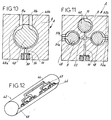
- L feed element A consists of a single monolithic body 8 which, in the embodiment shown in FIGS. 3 and 4, is traversed longitudinally by a cylindrical bore 9 communicating, by a transition slot 10, with a longitudinal groove 12 of rectangular cross section.
- the bore 9 communicates with a central supply channel 11 formed in the body.
- the bores 9 and the groove 12 delimit the first and second distribution stages, respectively.
- the first material distribution stage is composed of two identical rules 13, of substantially semi-circular section and whose rounded back is pressed, by radial screws 14, against the cylindrical face of the bore 9 formed in the body.
- the part of each rule which is turned towards the other rule, comprises from upstream to downstream, on the one hand, a chamfer 15 delimiting a flow channel 16 communicating with the arrival channel 11, on the other hand, two symmetrical millings 21 whose sloping bottoms form a dihedral distribution from the outlet of the inlet channel 11, in addition, a flat 17 delimiting a passage slot 18, and finally, a chamfer 19 decompressing the front material its introduction into the transition and decompression slot 10.
- the second distribution stage is composed of two rules 20, having a generally rectangular cross section with the back applied between the corresponding face of the groove 12 by transverse screws 22 accessible from outside the body, like those 14 fixing the rules of the first distribution stage.
- Each of these rules 20 comprises, as shown in FIG. 3, on the one hand and upstream, a chamfer 23 forming a compression channel, on the other hand, a flat face 24 delimiting with the face opposite the 'Another rule, a passage slot 25 and, finally, downstream, a chamfer 26, forming a channel decompressing the material before introduction thereof into the distribution stage.
- the supply body A is closed at each of its ends by panels 27 fixed by transverse screws 28 screwed into the body 8.
- the body 8 of the supply element is practically non-deformable at the pressures of use, since, for example, a body having a square cross section of 250 X 250 millimeters must withstand a pressure of at least 1000 bars to begin to deform at the level of the slot 25.
- This deformation has no effect on the element B of distribution of the die, element whose cross members 29 are linked to the supply body 8 by screws 30 having only a function of maintaining sealing pressure and not of friction fixing.
- the bores 30a formed in the crosspieces 29 tolerate a radial clearance preventing the screws 30 from influencing the position of the crosspieces.
- the bores 30a have a diameter of 29 mm.
- Another advantage of this arrangement of the body 8 is that it allows, by dismantling only one of the removable panels 27, immediate access to the two distribution stages to remove the rules, for example, to adjust their dimensions, for example successive touch-ups, so as to obtain, for a given synthetic material, a constant flow over the entire width of the dispensing slot.
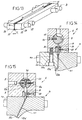
- the distribution stage B represented in FIG. 13, is constituted, as described above, by two crosspieces 29 produced in solid bars of stabilized hard steel, machined, put into tightening condition, heated to 350 ° C. a many times before being corrected. After receiving an anti-corrosion treatment, such as hard chrome plating or chemical nickel plating, each rule is polished and glazed. They are linked to each other by enclosing two end spacers 31 determining their air gap E, visible in FIGS. 3 and 13. This connection is provided exclusively by bolts 32 passing through their end zones comprising the spacers 31.
- each of the crosspieces has a section of 140 X 140 millimeters. They are tightened by four studs with a diameter of 50 millimeters. With this construction, no deformation can occur before the pressure in the air gap E reaches a value greater than 450 or 500 bars, that is to say at pressure values much greater than those used for extrusion. synthetic materials.
- the crossbars 29 are arranged to form two lips 33 which, as shown in FIG. 3, can be parallel to the distribution slot 11, curved at their ends, as shown for the lips 33a and 33b in the figure. 14, or inclined relative to the trajectory of the material in the body of the feed, as shown for the lips 33c and 33d in FIG. 15.
- the distribution element composed of the two cross members 29 assembled together, forms a sub-assembly of the die which is easily interchangeable for adaptation to needs. Interchangeability is effected by removing only the screws 30 ensuring the sealed contact of the distribution element B against the supply element A.
- each of the two cross-members 29 comprises, upstream from its flat face delimiting the slot 1, a chamfer 35 forming, downstream, from the second distribution stage of the supply body, a compression and guide channel for material toward the exit slit.
- the first distribution stage in the supply body A which, in the previous embodiment included two opposite rules, may also include a single cylindrical rule ensuring the distribution of material.
- the rule 40 having at least at its ends, a cross section identical, apart from play, to that of the longitudinal bore 9, comprises, on half of its periphery, a distribution machining having, going from the outlet of the feed channel 11 to the transition slot 10, a decreasing depth and an increasing width, as the sections of FIGS. 7 to 9 clearly show.
- FIG. 12 shows a rule 43 making it possible to obtain the same distribution by means of a succession of channels 44-45-46 which split on the way downstream.
- the channels 46 communicate in a common milling 47 ensuring the distribution and guiding of the material up to the transition and decompression slot 10.
- FIG. 10 shows that the same cylindrical rule 48 can comprise, on both sides, distribution machining operations 49 of the type shown in FIG. 6 or of the type shown in FIG. 12. Each of these machining operations is supplied by a channel input 11a and 11b, itself supplied by an extruder or by two different extruders, providing the same flow of material, or different waste.
- the two channels 49a-49b communicate with the same transition slot 10, arranged upstream of the second distribution stage.
- the distribution rule 48 is linked to the body 8 by fixing screws accessible from the outside cooperating with each of its ends.
- FIG. 11 shows that it is also possible, in the same body 8, to divide the first distribution stage into several zones each supplied with one or more materials.
- the two rules 48 of the type described in FIG. 10, each ensure the distribution of two different materials reaching them through inlet orifices 51a-51b, 52a-52b, while rule 40 ensures the distribution of only one type of material brought to it by the inlet channel 11.
- the different rules are arranged in different bores 9, each communicating with a primary transition slot 53, communicating itself with the transition slot 10 bringing the material to the second distribution stage.
- a grid 34 is interposed between the transition slot 10 and the second distribution stage.
- This grid is, for example, composed of a rectified, chromed sheet, perforated to 60% by transverse bores having a diameter of the order of 3 millimeters.
- This arrangement favors the mixing of the layers formed upstream and makes it possible, among other things, to bond two layers of thermoplastic material which usually delaminate.
- This mixing grid it is thus possible to produce a complex film composed of three layers of different materials having excellent cohesion between them, whereas, according to the traditional method, it would have been necessary to add two additional layers to ensure the connection between these layers of matter.
- the flat die according to the invention can, according to the synthetic materials to be cut, present various configurations, some of which are shown in FIGS. 14 and 15.
- the supply element A comprises, in addition to and upstream of the first stage of distribution of the supply body 8, a grid 55 which, forming a filter holder, supports the minus one and preferably two filters 56.
- the grid 55 is made of a metal sheet having a thickness of the order of 3 millimeters, and in which are formed, on 60% of its face forming a filtering surface, transverse perforations having a diameter of the order of 3 millimeters.
- the grid 55 is arranged in a housing arranged in the two rules 13a-13b, but it is obvious that it can also be arranged upstream of the bore 9, c ' is to say in a housing formed in the body 8 and not in the rules.
- This arrangement has many advantages compared to the traditional solution, which it replaces and which consists in placing the filter at the extruder outlet. Indeed, for the same pressure drop on the synthetic material circuit, the arrangement of the filters in the immediate vicinity of the first distribution zone of the material makes it possible to increase the filtration surface, and to collect all the waste of material and other carbonization products which normally accumulate in the change of direction areas between the extruder and the outlet slot.
- the filters 56 may be identical or be of different passages.
- the grid 55 and filters 56 assembly rests freely in the rules 13a and is trapped between the end panels 27 of the body 8 of the supply element. To change the filters, it suffices, with the machine stopped, to remove one of the panels 27 and to replace the grid 55 carrying the used filters with another grid 55 carrying clean filters. This operation lasts only a few minutes and is very easy.
- the flat die according to the invention not only is simpler to produce and less expensive than traditional dies, but also allows, by better resisting the extrusion forces, to work materials having a lower grade, or to work at a lower extrusion temperature, reducing the oxidation of the synthetic material, but also the release of smoke at the outlet of the die.
Landscapes
- Engineering & Computer Science (AREA)
- Mechanical Engineering (AREA)
- Manufacturing & Machinery (AREA)
- Extrusion Moulding Of Plastics Or The Like (AREA)
Applications Claiming Priority (2)
| Application Number | Priority Date | Filing Date | Title |
|---|---|---|---|
| FR9213796A FR2697774B1 (fr) | 1992-11-10 | 1992-11-10 | Filière plate pour l'extrusion de film, feuille ou plaque en matière synthétique. |
| FR9213796 | 1992-11-10 |
Publications (2)
| Publication Number | Publication Date |
|---|---|
| EP0597781A1 true EP0597781A1 (de) | 1994-05-18 |
| EP0597781B1 EP0597781B1 (de) | 1997-01-29 |
Family
ID=9435606
Family Applications (1)
| Application Number | Title | Priority Date | Filing Date |
|---|---|---|---|
| EP93420446A Expired - Lifetime EP0597781B1 (de) | 1992-11-10 | 1993-11-09 | Breitschlitzdüse zur Film-, Folien- oder Plattenextrusion |
Country Status (3)
| Country | Link |
|---|---|
| EP (1) | EP0597781B1 (de) |
| DE (1) | DE69307834T2 (de) |
| FR (1) | FR2697774B1 (de) |
Cited By (6)
| Publication number | Priority date | Publication date | Assignee | Title |
|---|---|---|---|---|
| US4589631A (en) * | 1984-09-28 | 1986-05-20 | United States Surgical Corporation | Surgical staple remover |
| DE102007052996A1 (de) | 2007-11-05 | 2009-05-07 | Beiersdorf Ag | Beschichtungswerkzeug zum Beschichten flächiger Materialien |
| US7690902B2 (en) * | 2002-06-20 | 2010-04-06 | 3M Innovative Properties Company | Nonwoven web forming apparatus |
| CN101940997A (zh) * | 2009-05-19 | 2011-01-12 | 纳瑞精密设备有限公司 | 用于缝模的改进的间隙调节装置、缝模以及具有上述间隙调节装置和缝模的喷涂设备 |
| CN107599346A (zh) * | 2017-09-12 | 2018-01-19 | 台州市黄岩晶威模具有限公司 | 一种电池阻隔膜的成型模头 |
| CN110733169A (zh) * | 2019-10-09 | 2020-01-31 | 宁波海曙广运机电工程有限公司 | 一种便于穿光纤的光缆挤塑模具 |
Citations (10)
| Publication number | Priority date | Publication date | Assignee | Title |
|---|---|---|---|---|
| US2628386A (en) * | 1952-04-29 | 1953-02-17 | Modern Plastic Machinery Corp | Web extrusion die |
| US2813301A (en) * | 1954-12-13 | 1957-11-19 | Monsanto Chemicals | Sheeting die |
| US2897541A (en) * | 1956-12-03 | 1959-08-04 | Nixon Nitration Works | Apparatus for extruding sheets with striped pattern |
| US3000054A (en) * | 1958-06-27 | 1961-09-19 | Kalle Ag | Extrusion die device |
| US3085289A (en) * | 1961-04-03 | 1963-04-16 | Jurian W Van Riper | Plastic material extrusion head |
| US3133313A (en) * | 1962-10-30 | 1964-05-19 | Nat Distillers Chem Corp | Extrusion die mechanism |
| US3191228A (en) * | 1961-03-23 | 1965-06-29 | Schluter Werner | Apparatus for making thermoplastic tiles with color effects |
| FR2351776A1 (fr) * | 1976-05-19 | 1977-12-16 | Dynamit Nobel Ag | Procede et dispositif d'extrusion de bandes de matieres thermoplastiques comportant un dessin |
| JPS57100032A (en) * | 1980-12-15 | 1982-06-22 | Sekisui Plastics Co Ltd | Method and apparatus for manufacturing thermoplastic resin sheet like object |
| JPS63256418A (ja) * | 1987-04-15 | 1988-10-24 | Toray Ind Inc | 製膜口金 |
-
1992
- 1992-11-10 FR FR9213796A patent/FR2697774B1/fr not_active Expired - Fee Related
-
1993
- 1993-11-09 DE DE69307834T patent/DE69307834T2/de not_active Expired - Fee Related
- 1993-11-09 EP EP93420446A patent/EP0597781B1/de not_active Expired - Lifetime
Patent Citations (10)
| Publication number | Priority date | Publication date | Assignee | Title |
|---|---|---|---|---|
| US2628386A (en) * | 1952-04-29 | 1953-02-17 | Modern Plastic Machinery Corp | Web extrusion die |
| US2813301A (en) * | 1954-12-13 | 1957-11-19 | Monsanto Chemicals | Sheeting die |
| US2897541A (en) * | 1956-12-03 | 1959-08-04 | Nixon Nitration Works | Apparatus for extruding sheets with striped pattern |
| US3000054A (en) * | 1958-06-27 | 1961-09-19 | Kalle Ag | Extrusion die device |
| US3191228A (en) * | 1961-03-23 | 1965-06-29 | Schluter Werner | Apparatus for making thermoplastic tiles with color effects |
| US3085289A (en) * | 1961-04-03 | 1963-04-16 | Jurian W Van Riper | Plastic material extrusion head |
| US3133313A (en) * | 1962-10-30 | 1964-05-19 | Nat Distillers Chem Corp | Extrusion die mechanism |
| FR2351776A1 (fr) * | 1976-05-19 | 1977-12-16 | Dynamit Nobel Ag | Procede et dispositif d'extrusion de bandes de matieres thermoplastiques comportant un dessin |
| JPS57100032A (en) * | 1980-12-15 | 1982-06-22 | Sekisui Plastics Co Ltd | Method and apparatus for manufacturing thermoplastic resin sheet like object |
| JPS63256418A (ja) * | 1987-04-15 | 1988-10-24 | Toray Ind Inc | 製膜口金 |
Non-Patent Citations (2)
| Title |
|---|
| PATENT ABSTRACTS OF JAPAN vol. 13, no. 52 (M - 794)<3400> 7 February 1989 (1989-02-07) * |
| PATENT ABSTRACTS OF JAPAN vol. 6, no. 193 (M - 160)<1071> 2 October 1982 (1982-10-02) * |
Cited By (7)
| Publication number | Priority date | Publication date | Assignee | Title |
|---|---|---|---|---|
| US4589631A (en) * | 1984-09-28 | 1986-05-20 | United States Surgical Corporation | Surgical staple remover |
| US7690902B2 (en) * | 2002-06-20 | 2010-04-06 | 3M Innovative Properties Company | Nonwoven web forming apparatus |
| DE102007052996A1 (de) | 2007-11-05 | 2009-05-07 | Beiersdorf Ag | Beschichtungswerkzeug zum Beschichten flächiger Materialien |
| CN101940997A (zh) * | 2009-05-19 | 2011-01-12 | 纳瑞精密设备有限公司 | 用于缝模的改进的间隙调节装置、缝模以及具有上述间隙调节装置和缝模的喷涂设备 |
| CN101940997B (zh) * | 2009-05-19 | 2013-06-12 | 纳瑞精密设备有限公司 | 用于缝模的改进的间隙调节装置、缝模以及具有上述间隙调节装置和缝模的喷涂设备 |
| CN107599346A (zh) * | 2017-09-12 | 2018-01-19 | 台州市黄岩晶威模具有限公司 | 一种电池阻隔膜的成型模头 |
| CN110733169A (zh) * | 2019-10-09 | 2020-01-31 | 宁波海曙广运机电工程有限公司 | 一种便于穿光纤的光缆挤塑模具 |
Also Published As
| Publication number | Publication date |
|---|---|
| DE69307834D1 (de) | 1997-03-13 |
| FR2697774A1 (fr) | 1994-05-13 |
| FR2697774B1 (fr) | 1994-12-23 |
| EP0597781B1 (de) | 1997-01-29 |
| DE69307834T2 (de) | 1997-05-28 |
Similar Documents
| Publication | Publication Date | Title |
|---|---|---|
| BE1005015A3 (fr) | Procede et appareillage destines a la formation d'un article presentant plusieurs densites et/ou geometries de cellules. | |
| EP0778074B1 (de) | Anorganisches rohrförmiges Filterelement mit Kanälen die einen nicht-kreisförmigen Durchschnitt und optimierte Profile aufweisen | |
| CA1119392A (fr) | Dispositif pour la fabrication de corps a structure alveolaire par extrusion d'une matiere ceramique, et procede de fabrication dudit dispositif | |
| EP0686424B1 (de) | Anorganisches Mehrkanal-Filterelement zum Filtrieren von Fluiden | |
| EP0778073B1 (de) | Anorganisches rohrförmiges Filterelement mit hoher Filteroberfläche und Festigkeit | |
| EP0597781B1 (de) | Breitschlitzdüse zur Film-, Folien- oder Plattenextrusion | |
| US8262908B2 (en) | Rotary cartridge filter | |
| FR2797198A1 (fr) | Membrane pour filtration tangentielle et son procede de fabrication | |
| FR2699979A1 (fr) | Conduit multicouche et filière pour sa fabrication. | |
| EP2464505A1 (de) | Verfahren zur reparatur einer wand aus mehreren schichten | |
| EP0236645B1 (de) | Vorrichtung und Verfahren zum Extrudieren von Kunststoffrohren mit mehrschichtigen Wänden | |
| FR2723014A1 (fr) | Procede et dispositif de correction de l'ovalisation de cylindres de coulee continue de bande metallique | |
| BE1011647A3 (fr) | Filiere d'extrusion en nid d'abeilles et son procede de fabrication. | |
| EP0737561A1 (de) | Extrusionsdüse für Zweischichtprofilen | |
| FR2529485A1 (fr) | Procede pour changer la distribution, en largeur, de l'epaisseur d'une bande de metal | |
| CA2386372C (fr) | Cylindre de coulee continue de bande metallique comprenant un circuit de refroidissement | |
| EP0186545A1 (de) | Vakuumbandfilter mit einer Dichtungsanlage zwischen einem Tragband und einem mit Abteilungen versehenen Saugkasten | |
| FR2930003A1 (fr) | Organe de machine hydraulique a bord renforce contre l'abrasion et machine hydraulique mettant en oeuvre un tel organe. | |
| EP0617992A1 (de) | Filter zur Filtrierung von geschmolzenem Harz und Filtriereinrichtung zur Bildung mehrschichtigen Harzes | |
| CA2429635A1 (fr) | Dispositif d'extrusion pour fabriquer un produit a base d'un melange caoutchouteux | |
| FR2472970A1 (fr) | Organe de boudineuse tel que vis ou cylindre | |
| EP1925722A1 (de) | Mahlgarnitur zum Mahlen von Fasern, insbesondere Papierfasern und Mahlmaschine mit einer solchen Mahlgarnitur | |
| FR2867401A1 (fr) | Planeuse a entraxe variable | |
| WO2000005054A1 (fr) | Dispositif de regulation de l'epaisseur d'une paraison dans une machine d'extrusion-soufflage | |
| EP1979077B1 (de) | Filterungselement |
Legal Events
| Date | Code | Title | Description |
|---|---|---|---|
| PUAI | Public reference made under article 153(3) epc to a published international application that has entered the european phase |
Free format text: ORIGINAL CODE: 0009012 |
|
| AK | Designated contracting states |
Kind code of ref document: A1 Designated state(s): BE DE FR GB IT |
|
| 17P | Request for examination filed |
Effective date: 19940419 |
|
| 17Q | First examination report despatched |
Effective date: 19950905 |
|
| GRAG | Despatch of communication of intention to grant |
Free format text: ORIGINAL CODE: EPIDOS AGRA |
|
| GRAH | Despatch of communication of intention to grant a patent |
Free format text: ORIGINAL CODE: EPIDOS IGRA |
|
| GRAH | Despatch of communication of intention to grant a patent |
Free format text: ORIGINAL CODE: EPIDOS IGRA |
|
| GRAA | (expected) grant |
Free format text: ORIGINAL CODE: 0009210 |
|
| AK | Designated contracting states |
Kind code of ref document: B1 Designated state(s): BE DE FR GB IT |
|
| REF | Corresponds to: |
Ref document number: 69307834 Country of ref document: DE Date of ref document: 19970313 |
|
| ITF | It: translation for a ep patent filed |
Owner name: 0508;05TOFJACOBACCI & PERANI S.P.A. |
|
| GBT | Gb: translation of ep patent filed (gb section 77(6)(a)/1977) |
Effective date: 19970429 |
|
| PLBE | No opposition filed within time limit |
Free format text: ORIGINAL CODE: 0009261 |
|
| STAA | Information on the status of an ep patent application or granted ep patent |
Free format text: STATUS: NO OPPOSITION FILED WITHIN TIME LIMIT |
|
| 26N | No opposition filed | ||
| REG | Reference to a national code |
Ref country code: GB Ref legal event code: IF02 |
|
| PGFP | Annual fee paid to national office [announced via postgrant information from national office to epo] |
Ref country code: DE Payment date: 20021015 Year of fee payment: 10 |
|
| PGFP | Annual fee paid to national office [announced via postgrant information from national office to epo] |
Ref country code: BE Payment date: 20021030 Year of fee payment: 10 |
|
| PGFP | Annual fee paid to national office [announced via postgrant information from national office to epo] |
Ref country code: GB Payment date: 20021106 Year of fee payment: 10 |
|
| PG25 | Lapsed in a contracting state [announced via postgrant information from national office to epo] |
Ref country code: GB Free format text: LAPSE BECAUSE OF NON-PAYMENT OF DUE FEES Effective date: 20031109 |
|
| PG25 | Lapsed in a contracting state [announced via postgrant information from national office to epo] |
Ref country code: BE Free format text: LAPSE BECAUSE OF NON-PAYMENT OF DUE FEES Effective date: 20031130 |
|
| BERE | Be: lapsed |
Owner name: *LES PLASTIQUES DE LA DEOME Effective date: 20031130 |
|
| PG25 | Lapsed in a contracting state [announced via postgrant information from national office to epo] |
Ref country code: DE Free format text: LAPSE BECAUSE OF NON-PAYMENT OF DUE FEES Effective date: 20040602 |
|
| GBPC | Gb: european patent ceased through non-payment of renewal fee |
Effective date: 20031109 |
|
| PGFP | Annual fee paid to national office [announced via postgrant information from national office to epo] |
Ref country code: IT Payment date: 20091125 Year of fee payment: 17 Ref country code: FR Payment date: 20091026 Year of fee payment: 17 |
|
| REG | Reference to a national code |
Ref country code: FR Ref legal event code: ST Effective date: 20110801 |
|
| PG25 | Lapsed in a contracting state [announced via postgrant information from national office to epo] |
Ref country code: FR Free format text: LAPSE BECAUSE OF NON-PAYMENT OF DUE FEES Effective date: 20101130 |
|
| PG25 | Lapsed in a contracting state [announced via postgrant information from national office to epo] |
Ref country code: IT Free format text: LAPSE BECAUSE OF NON-PAYMENT OF DUE FEES Effective date: 20101109 |