EP0597624A1 - Energy absorbing mounting systems for vehicle windows - Google Patents
Energy absorbing mounting systems for vehicle windows Download PDFInfo
- Publication number
- EP0597624A1 EP0597624A1 EP93308799A EP93308799A EP0597624A1 EP 0597624 A1 EP0597624 A1 EP 0597624A1 EP 93308799 A EP93308799 A EP 93308799A EP 93308799 A EP93308799 A EP 93308799A EP 0597624 A1 EP0597624 A1 EP 0597624A1
- Authority
- EP
- European Patent Office
- Prior art keywords
- window
- poly
- vehicle
- head
- break
- Prior art date
- Legal status (The legal status is an assumption and is not a legal conclusion. Google has not performed a legal analysis and makes no representation as to the accuracy of the status listed.)
- Granted
Links
Images


Classifications
-
- B—PERFORMING OPERATIONS; TRANSPORTING
- B60—VEHICLES IN GENERAL
- B60J—WINDOWS, WINDSCREENS, NON-FIXED ROOFS, DOORS, OR SIMILAR DEVICES FOR VEHICLES; REMOVABLE EXTERNAL PROTECTIVE COVERINGS SPECIALLY ADAPTED FOR VEHICLES
- B60J1/00—Windows; Windscreens; Accessories therefor
- B60J1/08—Windows; Windscreens; Accessories therefor arranged at vehicle sides
-
- B—PERFORMING OPERATIONS; TRANSPORTING
- B60—VEHICLES IN GENERAL
- B60J—WINDOWS, WINDSCREENS, NON-FIXED ROOFS, DOORS, OR SIMILAR DEVICES FOR VEHICLES; REMOVABLE EXTERNAL PROTECTIVE COVERINGS SPECIALLY ADAPTED FOR VEHICLES
- B60J10/00—Sealing arrangements
- B60J10/30—Sealing arrangements characterised by the fastening means
-
- B—PERFORMING OPERATIONS; TRANSPORTING
- B60—VEHICLES IN GENERAL
- B60J—WINDOWS, WINDSCREENS, NON-FIXED ROOFS, DOORS, OR SIMILAR DEVICES FOR VEHICLES; REMOVABLE EXTERNAL PROTECTIVE COVERINGS SPECIALLY ADAPTED FOR VEHICLES
- B60J10/00—Sealing arrangements
- B60J10/70—Sealing arrangements specially adapted for windows or windscreens
Definitions
- the present invention relates to energy absorbing mounting systems for vehicle windows, particularly for automobiles, which are safe for impact collisions, and in particular vehicle impact collisions.
- Tempered glass places the two outer surfaces of the glass into compression. Therefore when the glass is impacted it will shatter into very small pieces. Tempered glass has replaced annealed glass in window openings of motor vehicles. Annealed glass breaks into large dagger-like shards that can easily lacerate and seriously injure a vehicle occupant. While tempered glass has reduced lacerations, there remain several problems.
- Tempered glass can cause laceration of an occupant because the small fragments have very sharp edges; and if a tempered glass window breaks, pieces of glass remain embedded in the edge of the window. This may cause parts of a person's body to be raked along the edge of the window and result in serious lacerations.
- tempered glass Since tempered glass will shatter, it does not offer the vehicle occupant any protection from being ejected from the passenger compartment. If the vehicle is impacted from the side, the passenger could be partly or wholly ejected out through the window opening. If the vehicle begins to tumble in a rollover then the occupant could be partially or fully ejected and could incur a serious or a fatal injury once parts of the body are outside the vehicle.
- Windshields for example, are composed of two layers of glass separated with a thin layer of plastic.
- the inner layer made of poly (vinyl butyral), holds the broken glass together upon vehicular impact.
- a further refinement is found in that a second plastic layer is applied to the inner surface of the window.
- a moveable window design with a combination of an inner plastic layer and an outer glass layer is known.
- This window is intended to contain the occupant within the vehicle during a side impact collision.
- This is accomplished by a multi-part structure composed of a plastic frame that moves up and down in a special track design.
- the plastic frame has an edge in the shape of a "T,” and acts to sandwich together the outer glass layer and the inner plastic layer.
- the disadvantages are that the inner plastic layer is prone to scratching, reducing driver visibility, and the frame adds weight to the glazing structure.
- thermoplastic window for motor vehicles US-A-4,635,420 describes an acrylic window material that is ultrasonically welded to a plastic gasket. A safety feature is disclosed where grooves or notches are placed inward from the edge of the acrylic window to facilitate breakaway zones. Two disadvantages in this type of gasket installation are that it is not commonly used by original equipment manufacturers and is not economical to manufacture.
- Another patent describes a synthetic resin window for a vehicle that has a frame or gasket molded from the same synthetic resin material. This window is lightweight yet does not incorporate any feature that makes it safe during a potential side impact collision.
- a window module comprising:
- a monolithic glazing structure composed of a thermoplastic resin with a window mounting system that can reduce lacerations, produce no head injuries and provide occupant containment.
- a further benefit may be from a reduction in weight of the window structure.
- FIGS. 1, 2, 3, 4, 5, and 6 there is shown a synthetic resin window according to one embodiment of the present invention, which may be used in an automotive vehicle.
- the window module is designated by reference numeral 1, and is made of an appropriate thermoplastic resin by means of an injection molding or thermoforming process, as will be described hereinafter, and secured to a relevant vehicle chassis panel 6 with a mounting system.
- the window module 1 includes a window body portion 4 in the form of a sheet of transparent or semi-transparent synthetic resin, such as polycarbonate resin, acrylic resin or polyglutarimide resin.
- the window module 1 further includes a frame portion 5 extending along the peripheral edge of the window body portion 4.
- An abrasion resistant coating 10 covers the surfaces of the window body portion 4. If there is not a molded frame portion 5, a pressure sensitive foam tape, or sealant, such as polyurethane, 16 can be used as hereinafter described.
- a notch or groove 9 cut or molded into the window body portion 4 will enhance the formation of a breakaway zone 14.
- notches or other shaped grooves 9 can be cut or molded into one or both sides of the synthetic resin glazing material.
- Some of the possible shapes shown in FIG. 3 can be cut or molded into the synthetic resin glazing materials as taught by US-A-4,635,420.
- a double sided adhesive foam strip 16 is adhered around the edge of the glazing material.
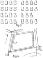
- FIG. 4 and FIG.5 a typical motor vehicle window aperture 8 is shown on the rear side.
- the metal edge of the aperture, as part of the chassis panel 6, has bolt holes 13.
- FIG. 5 is a cross section of the window module 1 installed in a window aperture 8.
- the thermoplastic window material 4 is encapsulated by a RIM mounting frame 5.
- a mounting bolt 7 has its bolt head 18 embedded in the interior facing section of the RIM 12. The mounting bolt attaches the window module 1 to the motor vehicle chassis panel 6 using a threaded nut 15.
- FIG. 6 shows a thermoplastic window 4 installed in a door 20.
- the frame 21 of the upper portion of the door 28, holds the window material in a track 22.
- the track acts to absorb energy of an impact and functionally allows the thermoplastic window 4 to travel up and down.
- the frame may be designed with a U-shaped channel to accommodate the edges of the ARC coated window.
- the frame may be designed in conjunction with the above mentioned plastic windows to optimize the energy absorbing characteristics in a vehicle crash environment.
- the thermoplastic resin can be any high modulus transparent material, such as poly (methyl methacrylate) (PMMA), impact modified poly (methyl methacrylate), acrylic copolymers, poly (methyl methacrylate-co-alkyl acrylate) wherein the alkyl group contains 1 to 8 carbon atoms, acrylic blends, acrylic alloys, poly (vinyl chloride), poly (styrene-co-acrylonitrile) wherein the acrylonitrile polymer comprises up to 40% of the copolymer, polycarbonate, poly (ethylene terephthalate), polystyrene, poly (styrene-co-methyl methacrylate), poly ( alpha - methylstyrene-co-methyl methacrylate), poly ( alpha -methylstyrene-co-alkyl acrylate) wherein the alkyl group contains 1 to 8 carbon atoms, poly (vinyl acetate), poly (ester carbonate), polyarylate, poly (ether sulfone), or
- thermoplastic glazing material should have at least one of the following criteria: an elastic modulus in the range of 2.0 to 4.2 GPa, a coefficient of thermal expansion of 4 to 8 ⁇ 10 ⁇ 5 cm/cm/°C at room temperature, and a continuous service temperature of at least 70° C or more for an acrylic thermoplastic.
- thermoplastic resins are above about 115° C for PMMI, and above about 110°C for polycarbonate. These conditions provide a window that will not flutter when driven at high vehicle velocities, does not greatly expand its dimensions with temperature and maintains its integrity at the high temperatures that vehicles can reach. It is possible that plastic fillers, impact modifiers, coefficient of thermal expansion modifiers, continuous service temperature modifiers, stiffness modifiers, such as glass fillers; other plastic additives, and stabilizers can be used to modify other thermoplastic materials to these performance criteria by any person knowledgeable in plastic compounding technology. These glazing materials may be colored or tinted, for example, to reduce solar transmission levels.
- thermoplastics are usually formed into the shape and size of a window by using sheet or molding powder (pellets).
- the thermoplastic sheet can be from about 1.5 to 6 mm in thickness and drape-formed or thermoformed using an appropriate mold.
- the plastic sheet is heated to a temperature so that it softens and can easily take on the shape of a mold.
- the window thickness can be from between about 1.5 to 6 mm.
- the window 4 used in this invention has been treated on both sides with an abrasion resistant coating 10.
- This provides a hard surface that is not easily scratched.
- Coatings such as polysiloxanes, transparent thermosetting resins, UV-curable coatings, polyurethanes, or diamond-like abrasion resistant coatings may be practical for this use. Coatings may be applied by plasma deposition, ion implantation, ion-assisted coating, evaporation, sputter deposition, physical or chemical vapor deposition, thermal spraying, and plasma assisted depositions. Other abrasion resistant coatings are known in the art.
- thermoplastic part Before the coating process begins, the thermoplastic part is annealed in an oven to remove any residual stress.
- the polysiloxane used in this invention is applied in conjunction with a primer and is typically coated by dipping the plastic glazing part into a liquid coating solution. However, flow, sprayable, curtain and other coating techniques may also be used. After each coating step the part is dried in an oven at elevated temperature. Any hard coating could be used, though it would have to be compatible with both the thermoplastic and the mounting system.
- One adhesive used in this invention is a foam tape, made from acrylic based materials, and has a pressure sensitive adhesive on both sides of the tape. Or the tape could have a hot melt adhesive.
- the tape is typically 5 mm to 26 mm wide and from 1 mm to 7 mm thick.
- the foam density should be about from 0.3 to 0.8 grams per cubic centimeter.
- thermoplastic window such as polyurethane, or neoprene or any other type of foam material that can be formed into a tape with two adhesive layers.
- the tape should preferably be water and weather resistant. Any of these materials could be enhanced so that they meet these criteria by adding additives, stabilizers, plasticisers and blowing agents known in the art.
- the foam density is of importance in the performance of this invention. For instance, it has been shown that a tape of density in the lower part of the range given will tear during an impact to the plastic window, but a foam in the higher part of the density range will not tear. If the window does break, the foam with the higher density will more likely hold broken pieces in the plane of the window and may cause lacerations.
- the pressure sensitive adhesive on the vehicle side of the tape should be formulated to adhere well to the paint systems used on motor vehicles.
- the adhesive strength between the tape and the plastic or paint surface should be higher than the cohesive strength of the tape.
- a cohesive failure of the tape can be predicted by its mechanical properties.
- sealants could be used and might provide the same effect.
- Polyurethanes, silicones, and acrylic based sealants are commonly used in the automotive industry.
- Butyl rubber based products, polysulfides, terpolymers of ethylene, propylene and a non-conjugated diene, ethylene propylene dimers (EPDM), thermoplastic elastomers, and thermosets such as epoxies, and hot melts could also be used to bond the plastic window to the motor vehicle.
- An attachment system such as Velcro could be engineered to provide the energy absorbing design to hold the thermoplastic window at low to moderate head impact velocities. At high head impact velocities, the specially designed Velcro attachment system could then rip itself apart, safely releasing the window module.
- thermosets reaction injection molded thermosets
- PVC injected molded polyvinyl chloride
- Other thermoplastics could be molded around the window material such as PMMA, modified PMMA, PMMI, polycarbonate and other synthetic resins. These materials are used to form a frame around the window and then are mechanically or adhesively bonded to the window aperture.
- the energy dissipating characteristics of the RIM system may be improved by the following techniques to further reduce the potential for lacerations and head injuries to the occupant over a broader range of head impact velocities.
- One method is to bond the bolt heads to the RIM material. This may be done by applying a primer or an adhesion promoter to the bolt heads prior to injecting the RIM material. This may also be achieved by applying an adhesive at the RIM/bolt head interface to improve the pull-out strength of the bolt heads.
- Another method is to increase the dimensions of the bolt heads. This method would increase the surface area of the bolt head and would make it more difficult for the bolt head to pull out through the opening in the RIM material where the bolt protrudes toward the vehicle frame. This method would also increase the surface area of the bolt head that would be available to bond the bolt to the RIM material.
- Another method is to design the mounting system such that a bolt head and nut assembly clamps down on the RIM material instead of the compression stop on the bolt. This would prevent the bolt head from popping out of the RIM material and force the RIM material to tear either cohesively around the clamped area or adhesively at the interface where the RIM encapsulation is bonded to the plastic window.
- Another technique is to increase the number of bolts used to attach the window module to the vehicle. This would help to reduce the stress loads at each of the bolt locations and provide additional energy dissipation.
- the thickness of the RIM material that is holding the bolt head in the RIM could also be increased. This would allow the RIM to provide additional resistance and help prevent the bolt from pulling out.
- Another possibility is to use a slightly more rigid RIM material to hold the bolt heads in place during the head impact. Note that the above techniques may be used separately or in combination on any type of fixed window.
- a notch or groove 9 may be placed inward from the edge of the plastic window to provide a breakaway zone.
- Various types of notches are disclosed in U.S. Pat. No. 5,035,096. Any combination of notches could be used in conjunction with the window mounting techniques to define specific breakaway zones 14 in the plastic window.
- the notch depth is preferably between 10 and 80% of the thickness of the plastic window.
- the radius can be from about 5% of the part thickness to about 200% or more of the part thickness, and may be molded , cut, or machined into the thermoplastic glazing.
- the notch is designed in terms of radius, type of cross section, location along the perimeter (along any number or sections of the sides of the window), distance inward from the edge (1 to 100 mm, for example, so as to aesthetically pleasing) and depth, so that the section of the window inward of the notch or groove will break out along the notch at relatively high impact velocities, for example, above 32 kilometers per hour. At low to moderate head impact velocities, for example, 0 to 32 kilometers per hour, the notch should not break. This will provide for containment of the occupant under less severe impact conditions, greatly reducing the possibility of ejection of the occupant from the vehicle through the window opening.
- Tempered glass is a very high modulus, brittle material that is designed intentionally to break into small fragments upon impact. However, tempered glass breaks at an impact velocity that is relatively low compared to the typical crash velocities as specified in several government testing procedures (see 49CFR 571.214, below).
- thermoplastic materials in the invention are such that the plastic window will not break at the head velocities where tempered glass shatters, for example below 23 kilometers per hour. If used in combination with the mounting systems mentioned above, the whole glazing structure will be stretched or deflected out from the vehicle structure.
- the window module can be made to be pushed out so that the window remains intact and limits the likelihood of injury to the impacting occupant's head or body parts.
- the mounting system can be designed so that the window will be released from the vehicle in a safe manner.
- Either the window will detach itself from the mounting system, break along the breakaway zone cut into the window, or the window will break and any fragments will be safely released from the window frame by a notch breaking or, in one case, by a foam tape ripping itself apart.
- This invention is used for mounting plastic windows into motor vehicles.
- the types of windows are: windshields, moveable windows as found on the side of motor vehicles, side windows that do not move, opera windows, flipper windows, or other types of venting windows, and back windows.
- Types of motor vehicles are passenger cars, light trucks, multi-purpose vehicles, off-road vehicles, heavy trucks,buses, recreational vehicles and motor homes.
- HIC Head Injury Criteria
- 49CFR 571.208 the resultant head acceleration expressed as a multiple of g (the acceleration of gravity), where t1 and t2 are any two points in time during the impact which are separated by not more then a 36 millisecond time interval and where t1 and t2 are selected so as to maximize Eq. (1). If the HIC value is below 1000, then 49CFR 571.208 states that the potential for head injury is unlikely. If the HIC value is above 1000, then the potential for head injury is possible.
- the Chamois Laceration Scale is as follows: 0 Superficial Cuts Pass 1 Outer Layer Cuts Pass 2 Inner Layer Cuts Fail (Reference Society of Automotive Engineers Paper Number 860198 (1986).)
- Extruded sheet of PMMI 5 mm thick, is thermoformed into the shape and size of an automobile side quarter window.
- the plastic window is coated with an abrasion resistant coating, i.e., a polysiloxane.
- the window is pre-treated with a liquid primer and cleaner.
- Two automotive foam tapes with densities in the range of 0.5 to 0.65 and 0.6 to 0.75 grams per cubic centimeter, and 6.2 and 12.5 mm wide, are pressed onto the treated surface.
- the window and tape are then installed adhesively into a quarter window frame opening by revealing the second side of the foam tape.
- the window is tested by launching a human surrogate head (49 CFR572E defines head and geometry) at 26, 34 and 40 kilometers per hour towards the window. Data are collected regarding the head deceleration upon impact, the disposition of the window and any fragments, and the laceration is measured using a two-layer chamois skin placed over the head. The disposition, chamois laceration values, and HIC values of the window or its fragments are shown below.
- Extruded sheet of PMMI 5 mm thick, is thermoformed into the shape and size of an automobile side quarter window.
- the plastic window is dip coated with a polysiloxane abrasion resistant coating.
- a notch in the shape of a letter v, with a 60° angle, is cut 14mm inward from the outer edge of the window. The notch in several cases is from 2.5 to 3.0 mm deep.
- the window is pre-treated with a liquid primer and cleaner.
- Two automotive foam tapes with densities in the range of 0.5 to 0.65 grams per cubic centimeter, and 12.5 mm wide, are pressed onto the treated surface. The window and tape are then installed adhesively into a quarter window frame opening by revealing the second side of the foam tape.
- the window is mounted to the window aperture in a portion of the vehicle chassis panel.
- the window module is then tested by launching towards the test fixture a human surrogate head (49 CFR572E defines head and geometry) at 26, 34 and 40 kilometers per hour. Data are collected regarding the head deceleration upon impact, the disposition of the window and any fragments, and the laceration is measured using 2 layers of chamois skin placed over the head. The disposition, chamois laceration values, and HIC values of the window or its fragments are shown below.
- Extruded sheet of PMMI 5 mm thick, is thermoformed into the shape and size of an automobile side quarter window.
- the plastic window is dip coated with a polysiloxane abrasion resistant coating.
- the window can have a notch or groove machined inward from the perimeter with a depth of 1.0 to 3.0.mm.
- the window is pre-treated with a liquid primer and cleaner.
- the painted window frame is also pre-treated with a primer.
- a polyurethane or silicone sealant is applied between the window and the frame. The window is then installed into a quarter window frame opening.
- the window is mounted to the window aperture in a portion of the vehicle chassis panel .
- the window module is then tested by launching towards the test fixture a human surrogate head (49 CFR572E defines head and geometry) at 26, 34 and 40 kilometers per hour. Data are collected regarding the head deceleration upon impact, the disposition of the window and any fragments, and the laceration is measured using 2 layers of a chamois skin placed over the head. The disposition, chamois laceration values, and HIC values of the window or its fragments are shown below.
- Extruded sheet of PMMI 5 mm thick, is thermoformed into the shape and size of an automobile side quarter window.
- the plastic window is dip coated with a polysiloxane hard coat that provides abrasion resistance.
- the window is pre-treated with a liquid primer and cleaner.
- a mold cavity is positioned around the perimeter of the plastic window.
- Nine bolts 7 are also positioned around the perimeter such that the bolt heads 18 are embedded in the mold cavity.
- a polyurethane is reaction injection molded into the cavity and around the bolt heads to form the frame 5.
- the frame is attached to the quarter window aperture by aligning the bolts with the holes 13 located on the vehicle around the window opening and using nuts 15 to screw them in.
- the window is mounted to the window aperture in a portion of the vehicle chassis panel.
- the window module is then tested by launching towards the test fixture a human surrogate head (49 CFR572E defines head and geometry) at 23, 26, 34 and 40 kilometers per hour. Data are collected regarding the head deceleration upon impact, the disposition of the window and any fragments, and the laceration is measured using 2 layers of chamois over the head. The disposition of the window or its fragments is shown below.
- Extruded sheet of PMMI 4 and 5 mm thick
- the plastic window is flow coated with a silicone based hard coat that provides abrasion resistance and is subsequently cut to size.
- Extruded sheet of polycarbonate (PC), 4 mm thick is thermoformed into the shape of an automobile side quarter window and is subsequently cut to size.
- Each window 4 is then installed in a passenger car driver's door 20 that is equipped with a U-shaped sliding track 22 that allows the window to move up and down.
- the window is mounted to the window aperture in a portion of the vehicle chassis panel.
- the window module is then tested by launching towards the test fixture a human surrogate head (49 CFR572E defines head and geometry) at 18, 26, and 34 kilometers per hour. Data are collected regarding the head deceleration upon impact, the disposition of the window and any fragments, and the laceration is measured using 2 layers of chamois placed over the head. The disposition of the window or its fragments is shown below.
- Extruded sheet of PMMI 5 mm thick, is thermoformed into the shape and size of an automobile side quarter window.
- the plastic window is dip coated with a polysiloxane hard coat that provides abrasion resistance.
- the window is pre-treated with a liquid primer and cleaner.
- a mold cavity is positioned around the perimeter of the plastic window.
- Nine bolts 7 are also positioned around the perimeter such that the bolt heads 18 are embedded in the mold cavity.
- a polyurethane is reaction injection molded into the cavity and around the bolt heads to form the frame 5.
- the frame is attached to the quarter window aperture by aligning the bolts with the holes 13 located on the vehicle around the window opening and using nuts 15 to screw them in.
- the window is mounted to the window aperture in a portion of the vehicle chassis panel .
- the vehicle chassis panel adjacent to a vehicle seat is firmly attached to a test structure.
- SID anthropomorphic side impact dummy
- the window module is then tested by accelerating the whole test structure (dummy on bench adjacent to vehicle chassis panel) using a HYGE sled, where this acceleration results in head impact velocities of 36 to 37 kilometers per hour. Data are collected regarding the head deceleration upon impact, the disposition of the window and any fragments, and the laceration is measured using 2 layers of chamois skin placed over the head.
- HIC Head Velocity (km/hr) Window Disposition Chamois Laceration Scale HIC 36 module pop-out 0 ⁇ 1000 37 module pop-out 0 ⁇ 1000
- Extruded sheet of PMMI 5 mm thick, is thermoformed into the shape and size of an automobile side quarter window.
- the plastic window is dip coated with a polysiloxane abrasion resistant coating.
- a notch in the shape of a letter v, with a 60° angle, is cut 14mm inward from the outer edge of the several window.
- the notch is 3.0 mm deep.
- the window is pre-treated with a liquid primer and cleaner.
- An automotive foam tapes with densities in the range of 0.5 to 0.65 grams per cubic centimeter, and 6.2 and 12.5 mm wide, are pressed onto the treated surface.
- the window and tape are then installed adhesively into a quarter window frame opening by revealing the second side of the foam tape.
- the window is mounted to the window aperture in a portion of the vehicle chassis panel .
- the vehicle chassis panel adjacent to a vehicle seat is firmly attached to a test structure.
- SID anthropomorphic side impact dummy
- the window module is then tested by accelerating the whole test structure (dummy on bench adjacent to vehicle chassis panel) using a HYGE sled, where this acceleration results in head impact velocities of 36 to 37 kilometers per hour. Data are collected regarding the head deceleration upon impact, the disposition of the window and any fragments, and the laceration is measured using 2 layers of chamois skin placed over the head.
- Head Velocity (km/hr) Tape Width (mm) Notch Depth (mm) Window Disposition Chamois Laceration Scale Head Injury Criteria 42 12.5 3.0 break along notch 0 ⁇ 1000 38 12.5 3.0 break along notch 0 ⁇ 1000 38 6.2 0 window pop-out 0 ⁇ 1000
Landscapes
- Engineering & Computer Science (AREA)
- Mechanical Engineering (AREA)
- Window Of Vehicle (AREA)
- Laminated Bodies (AREA)
- Vehicle Interior And Exterior Ornaments, Soundproofing, And Insulation (AREA)
- Securing Of Glass Panes Or The Like (AREA)
- Injection Moulding Of Plastics Or The Like (AREA)
Abstract
Description
- The present invention relates to energy absorbing mounting systems for vehicle windows, particularly for automobiles, which are safe for impact collisions, and in particular vehicle impact collisions.
- Side and rear windows in motor vehicles are currently manufactured from float glass that has been tempered. Tempering of glass places the two outer surfaces of the glass into compression. Therefore when the glass is impacted it will shatter into very small pieces. Tempered glass has replaced annealed glass in window openings of motor vehicles. Annealed glass breaks into large dagger-like shards that can easily lacerate and seriously injure a vehicle occupant. While tempered glass has reduced lacerations, there remain several problems.
- Tempered glass can cause laceration of an occupant because the small fragments have very sharp edges; and if a tempered glass window breaks, pieces of glass remain embedded in the edge of the window. This may cause parts of a person's body to be raked along the edge of the window and result in serious lacerations.
- Since tempered glass will shatter, it does not offer the vehicle occupant any protection from being ejected from the passenger compartment. If the vehicle is impacted from the side, the passenger could be partly or wholly ejected out through the window opening. If the vehicle begins to tumble in a rollover then the occupant could be partially or fully ejected and could incur a serious or a fatal injury once parts of the body are outside the vehicle.
- Some work is known that attempts to improve the laceration and containment deficiency of tempered glass. Windshields, for example, are composed of two layers of glass separated with a thin layer of plastic. The inner layer, made of poly (vinyl butyral), holds the broken glass together upon vehicular impact. A further refinement is found in that a second plastic layer is applied to the inner surface of the window.
- A moveable window design with a combination of an inner plastic layer and an outer glass layer is known. This window is intended to contain the occupant within the vehicle during a side impact collision. This is accomplished by a multi-part structure composed of a plastic frame that moves up and down in a special track design. The plastic frame has an edge in the shape of a "T," and acts to sandwich together the outer glass layer and the inner plastic layer. The disadvantages are that the inner plastic layer is prone to scratching, reducing driver visibility, and the frame adds weight to the glazing structure.
- A few inventions have been described using thermoplastic window for motor vehicles. US-A-4,635,420 describes an acrylic window material that is ultrasonically welded to a plastic gasket. A safety feature is disclosed where grooves or notches are placed inward from the edge of the acrylic window to facilitate breakaway zones. Two disadvantages in this type of gasket installation are that it is not commonly used by original equipment manufacturers and is not economical to manufacture. Another patent describes a synthetic resin window for a vehicle that has a frame or gasket molded from the same synthetic resin material. This window is lightweight yet does not incorporate any feature that makes it safe during a potential side impact collision.
- In accordance with the present invention there is provided a window module comprising:
- a) a transparent thermoplastic glazing material having at least one of the following properties:
- 1) an elastic modulus not less than 2.0 GPA,
- 2) a coefficient of thermal expansion of 4 to 8 x 10⁻⁵ cm/cm/°C at room temperature
- 3) a continuous service temperature of at least 70°C, and
- 4) an abrasion resistant hard coating; and
- b) a system for mounting the thermoplastic glazing in a vehicle which permits the glazing material to be deflected partially or fully out of the plane of the window opening and absorbs energy on impact.
- It would be desirable to use a monolithic glazing structure composed of a thermoplastic resin with a window mounting system that can reduce lacerations, produce no head injuries and provide occupant containment. A further benefit may be from a reduction in weight of the window structure.
- The invention will now be described, by way of example, with reference to the following Figures in which:
- FIG. 1 is a perspective view of a side window module for an automotive vehicle according to one preferred embodiment of the invention;
- FIG. 2 is a fragmentary cross-sectional view of an embodiment of a sheet of thermoplastic glazing material;
- FIG. 3 is a schematic representation showing other variations in the embodiment of FIG. 2;
- FIG. 4 is a perspective view of another embodiment of the invention, i.e., a side window installation in a motor vehicle, using Reaction Injection Molded (RIM). FIG. 5 shows a cross section of the window assembly with frame and mountirig bolt;
- FIG. 5 is a section taken through the bottom of the side window in FIG. 4 showing a mounting bolt that attaches the window module to the vehicle chassis; and
- FIG. 6 is a perspective view of another embodiment of the invention referring to moveable window installations in a vehicle door frame.
- Referring now to FIGS. 1, 2, 3, 4, 5, and 6 there is shown a synthetic resin window according to one embodiment of the present invention, which may be used in an automotive vehicle. The window module is designated by
reference numeral 1, and is made of an appropriate thermoplastic resin by means of an injection molding or thermoforming process, as will be described hereinafter, and secured to a relevantvehicle chassis panel 6 with a mounting system. - The
window module 1 includes a window body portion 4 in the form of a sheet of transparent or semi-transparent synthetic resin, such as polycarbonate resin, acrylic resin or polyglutarimide resin. Thewindow module 1 further includes aframe portion 5 extending along the peripheral edge of the window body portion 4. An abrasionresistant coating 10 covers the surfaces of the window body portion 4. If there is not a moldedframe portion 5, a pressure sensitive foam tape, or sealant, such as polyurethane, 16 can be used as hereinafter described. A notch orgroove 9 cut or molded into the window body portion 4 will enhance the formation of abreakaway zone 14. - In FIG. 2 and FIG. 3 embodiments, notches or other
shaped grooves 9, can be cut or molded into one or both sides of the synthetic resin glazing material. Some of the possible shapes shown in FIG. 3 can be cut or molded into the synthetic resin glazing materials as taught by US-A-4,635,420. A double sidedadhesive foam strip 16 is adhered around the edge of the glazing material. - In FIG. 4 and FIG.5, a typical motor
vehicle window aperture 8 is shown on the rear side. The metal edge of the aperture, as part of thechassis panel 6, has bolt holes 13. - FIG. 5 is a cross section of the
window module 1 installed in awindow aperture 8. The thermoplastic window material 4 is encapsulated by aRIM mounting frame 5. A mounting bolt 7 has itsbolt head 18 embedded in the interior facing section of theRIM 12. The mounting bolt attaches thewindow module 1 to the motorvehicle chassis panel 6 using a threadednut 15. - FIG. 6 shows a thermoplastic window 4 installed in a
door 20. Theframe 21 of the upper portion of thedoor 28, holds the window material in atrack 22. The track acts to absorb energy of an impact and functionally allows the thermoplastic window 4 to travel up and down. The frame may be designed with a U-shaped channel to accommodate the edges of the ARC coated window. The frame may be designed in conjunction with the above mentioned plastic windows to optimize the energy absorbing characteristics in a vehicle crash environment. - The thermoplastic resin can be any high modulus transparent material, such as poly (methyl methacrylate) (PMMA), impact modified poly (methyl methacrylate), acrylic copolymers, poly (methyl methacrylate-co-alkyl acrylate) wherein the alkyl group contains 1 to 8 carbon atoms, acrylic blends, acrylic alloys, poly (vinyl chloride), poly (styrene-co-acrylonitrile) wherein the acrylonitrile polymer comprises up to 40% of the copolymer, polycarbonate, poly (ethylene terephthalate), polystyrene, poly (styrene-co-methyl methacrylate), poly (alpha- methylstyrene-co-methyl methacrylate), poly (alpha-methylstyrene-co-alkyl acrylate) wherein the alkyl group contains 1 to 8 carbon atoms, poly (vinyl acetate), poly (ester carbonate), polyarylate, poly (ether sulfone), or polyetherimide. One such acrylic copolymer could be a polyglutarimide and poly (methyl methacrylate) copolymer, also known as poly (methyl methacrylimide) (PMMI), i.e., US-A-4,246,374; 4,217,424; and 4,727,117 assigned to Rohm and Haas Co.; and others. The thermoplastic glazing material should have at least one of the following criteria: an elastic modulus in the range of 2.0 to 4.2 GPa, a coefficient of thermal expansion of 4 to 8 × 10⁻⁵ cm/cm/°C at room temperature, and a continuous service temperature of at least 70° C or more for an acrylic thermoplastic. Ranges for other thermoplastic resins are above about 115° C for PMMI, and above about 110°C for polycarbonate. These conditions provide a window that will not flutter when driven at high vehicle velocities, does not greatly expand its dimensions with temperature and maintains its integrity at the high temperatures that vehicles can reach. It is possible that plastic fillers, impact modifiers, coefficient of thermal expansion modifiers, continuous service temperature modifiers, stiffness modifiers, such as glass fillers; other plastic additives, and stabilizers can be used to modify other thermoplastic materials to these performance criteria by any person knowledgeable in plastic compounding technology. These glazing materials may be colored or tinted, for example, to reduce solar transmission levels.
- Any of the above thermoplastics are usually formed into the shape and size of a window by using sheet or molding powder (pellets). The thermoplastic sheet can be from about 1.5 to 6 mm in thickness and drape-formed or thermoformed using an appropriate mold. The plastic sheet is heated to a temperature so that it softens and can easily take on the shape of a mold.
- Another technique to form the windows is to injection mold pellets of the thermoplastics in an injection molding machine that will fill a mold cavity with the molten plastic material. The specific molding conditions are highly dependent on the thermal and flow properties of the material. For an optical application, it is best to mold under conditions that provide for the least amount of residual stress in the molded part. The window thickness can be from between about 1.5 to 6 mm.
- The window 4 used in this invention has been treated on both sides with an abrasion
resistant coating 10. This provides a hard surface that is not easily scratched. Coatings such as polysiloxanes, transparent thermosetting resins, UV-curable coatings, polyurethanes, or diamond-like abrasion resistant coatings may be practical for this use. Coatings may be applied by plasma deposition, ion implantation, ion-assisted coating, evaporation, sputter deposition, physical or chemical vapor deposition, thermal spraying, and plasma assisted depositions. Other abrasion resistant coatings are known in the art. - Before the coating process begins, the thermoplastic part is annealed in an oven to remove any residual stress. The polysiloxane used in this invention is applied in conjunction with a primer and is typically coated by dipping the plastic glazing part into a liquid coating solution. However, flow, sprayable, curtain and other coating techniques may also be used. After each coating step the part is dried in an oven at elevated temperature. Any hard coating could be used, though it would have to be compatible with both the thermoplastic and the mounting system.
- One adhesive used in this invention is a foam tape, made from acrylic based materials, and has a pressure sensitive adhesive on both sides of the tape. Or the tape could have a hot melt adhesive. The tape is typically 5 mm to 26 mm wide and from 1 mm to 7 mm thick. The foam density should be about from 0.3 to 0.8 grams per cubic centimeter.
- Other kinds of tapes could be used for the attachment of the thermoplastic window, such as polyurethane, or neoprene or any other type of foam material that can be formed into a tape with two adhesive layers. The tape should preferably be water and weather resistant. Any of these materials could be enhanced so that they meet these criteria by adding additives, stabilizers, plasticisers and blowing agents known in the art.
- The foam density is of importance in the performance of this invention. For instance, it has been shown that a tape of density in the lower part of the range given will tear during an impact to the plastic window, but a foam in the higher part of the density range will not tear. If the window does break, the foam with the higher density will more likely hold broken pieces in the plane of the window and may cause lacerations.
- The pressure sensitive adhesive on the vehicle side of the tape should be formulated to adhere well to the paint systems used on motor vehicles. The adhesive strength between the tape and the plastic or paint surface should be higher than the cohesive strength of the tape. A cohesive failure of the tape can be predicted by its mechanical properties.
- Other types of sealants could be used and might provide the same effect. Polyurethanes, silicones, and acrylic based sealants are commonly used in the automotive industry. Butyl rubber based products, polysulfides, terpolymers of ethylene, propylene and a non-conjugated diene, ethylene propylene dimers (EPDM), thermoplastic elastomers, and thermosets such as epoxies, and hot melts could also be used to bond the plastic window to the motor vehicle. An attachment system such as Velcro could be engineered to provide the energy absorbing design to hold the thermoplastic window at low to moderate head impact velocities. At high head impact velocities, the specially designed Velcro attachment system could then rip itself apart, safely releasing the window module.
- Other mounting methods such as polymeric encapsulation around the edge of the plastic glazing can be used. Two examples are reaction injection molded thermosets (RIM) or injected molded polyvinyl chloride (PVC). Other thermoplastics could be molded around the window material such as PMMA, modified PMMA, PMMI, polycarbonate and other synthetic resins. These materials are used to form a frame around the window and then are mechanically or adhesively bonded to the window aperture.
- The energy dissipating characteristics of the RIM system may be improved by the following techniques to further reduce the potential for lacerations and head injuries to the occupant over a broader range of head impact velocities. One method is to bond the bolt heads to the RIM material. This may be done by applying a primer or an adhesion promoter to the bolt heads prior to injecting the RIM material. This may also be achieved by applying an adhesive at the RIM/bolt head interface to improve the pull-out strength of the bolt heads.
- Another method is to increase the dimensions of the bolt heads. This method would increase the surface area of the bolt head and would make it more difficult for the bolt head to pull out through the opening in the RIM material where the bolt protrudes toward the vehicle frame. This method would also increase the surface area of the bolt head that would be available to bond the bolt to the RIM material.
- Another method is to design the mounting system such that a bolt head and nut assembly clamps down on the RIM material instead of the compression stop on the bolt. This would prevent the bolt head from popping out of the RIM material and force the RIM material to tear either cohesively around the clamped area or adhesively at the interface where the RIM encapsulation is bonded to the plastic window.
- Another technique is to increase the number of bolts used to attach the window module to the vehicle. This would help to reduce the stress loads at each of the bolt locations and provide additional energy dissipation. The thickness of the RIM material that is holding the bolt head in the RIM could also be increased. This would allow the RIM to provide additional resistance and help prevent the bolt from pulling out. Another possibility is to use a slightly more rigid RIM material to hold the bolt heads in place during the head impact. Note that the above techniques may be used separately or in combination on any type of fixed window.
- In combination with any of the above mentioned window mounting methods, a notch or
groove 9 may be placed inward from the edge of the plastic window to provide a breakaway zone. Various types of notches are disclosed in U.S. Pat. No. 5,035,096. Any combination of notches could be used in conjunction with the window mounting techniques to definespecific breakaway zones 14 in the plastic window. The notch depth is preferably between 10 and 80% of the thickness of the plastic window. In the breakaway zones the radius can be from about 5% of the part thickness to about 200% or more of the part thickness, and may be molded , cut, or machined into the thermoplastic glazing. - The notch is designed in terms of radius, type of cross section, location along the perimeter (along any number or sections of the sides of the window), distance inward from the edge (1 to 100 mm, for example, so as to aesthetically pleasing) and depth, so that the section of the window inward of the notch or groove will break out along the notch at relatively high impact velocities, for example, above 32 kilometers per hour. At low to moderate head impact velocities, for example, 0 to 32 kilometers per hour, the notch should not break. This will provide for containment of the occupant under less severe impact conditions, greatly reducing the possibility of ejection of the occupant from the vehicle through the window opening.
- This invention is based on mechanical and physical properties of the plastic glazing material and the mounting system used to bond the plastic to the vehicle window opening. Tempered glass is a very high modulus, brittle material that is designed intentionally to break into small fragments upon impact. However, tempered glass breaks at an impact velocity that is relatively low compared to the typical crash velocities as specified in several government testing procedures (see 49CFR 571.214, below).
- The properties of the thermoplastic materials in the invention are such that the plastic window will not break at the head velocities where tempered glass shatters, for example below 23 kilometers per hour. If used in combination with the mounting systems mentioned above, the whole glazing structure will be stretched or deflected out from the vehicle structure. By judiciously choosing the thickness of the window and specific mounting system, the window module can be made to be pushed out so that the window remains intact and limits the likelihood of injury to the impacting occupant's head or body parts. At very high head impact velocities the mounting system can be designed so that the window will be released from the vehicle in a safe manner. Either the window will detach itself from the mounting system, break along the breakaway zone cut into the window, or the window will break and any fragments will be safely released from the window frame by a notch breaking or, in one case, by a foam tape ripping itself apart.
- This invention is used for mounting plastic windows into motor vehicles. The types of windows are: windshields, moveable windows as found on the side of motor vehicles, side windows that do not move, opera windows, flipper windows, or other types of venting windows, and back windows. Types of motor vehicles are passenger cars, light trucks, multi-purpose vehicles, off-road vehicles, heavy trucks,buses, recreational vehicles and motor homes.
- The invention will now be described by way of the following Examples.
- In the following Examples, Head Injury Criteria (HIC) is determined in accordance with the following formula from 49CFR 571.208:

where a = the resultant head acceleration expressed as a multiple of g (the acceleration of gravity),
where t₁ and t₂ are any two points in time during the impact which are separated by not more then a 36 millisecond time interval and
where t₁ and t₂ are selected so as to maximize Eq. (1).
If the HIC value is below 1000, then 49CFR 571.208 states that the potential for head injury is unlikely. If the HIC value is above 1000, then the potential for head injury is possible.
The Chamois Laceration Scale is as follows:0 Superficial Cuts Pass 1 Outer Layer Cuts Pass 2 Inner Layer Cuts Fail
(Reference Society of Automotive Engineers Paper Number 860198 (1986).) - Extruded sheet of PMMI, 5 mm thick, is thermoformed into the shape and size of an automobile side quarter window. The plastic window is coated with an abrasion resistant coating, i.e., a polysiloxane. The window is pre-treated with a liquid primer and cleaner. Two automotive foam tapes, with densities in the range of 0.5 to 0.65 and 0.6 to 0.75 grams per cubic centimeter, and 6.2 and 12.5 mm wide, are pressed onto the treated surface. The window and tape are then installed adhesively into a quarter window frame opening by revealing the second side of the foam tape.
- The window is tested by launching a human surrogate head (49 CFR572E defines head and geometry) at 26, 34 and 40 kilometers per hour towards the window. Data are collected regarding the head deceleration upon impact, the disposition of the window and any fragments, and the laceration is measured using a two-layer chamois skin placed over the head. The disposition, chamois laceration values, and HIC values of the window or its fragments are shown below.
Head Velocity (km/hr) Tape Density (gm per cc) Tape width (mm) Window Disposition Chamois Laceration Scale Head Injury Criteria 26 0.5 to 0.65 12.5 no break 0 <1000 34 0.5 to 0.65 12.5 break 0 <1000 34 0.5 to 0.65 12.5 no break 0 <1000 40 0.5 to 0.65 12.5 no break 0 <1000 26 0.6 to 0.75 12.5 no break 0 <1000 34 0.6 to 0.75 12.5 break 0 <1000 40 0.6 to 0.75 12.5 break 0 <1000 30 0.5 to 0.65 6.2 no break 0 <1000 - Extruded sheet of PMMI, 5 mm thick, is thermoformed into the shape and size of an automobile side quarter window. The plastic window is dip coated with a polysiloxane abrasion resistant coating. A notch in the shape of a letter v, with a 60° angle, is cut 14mm inward from the outer edge of the window. The notch in several cases is from 2.5 to 3.0 mm deep. The window is pre-treated with a liquid primer and cleaner. Two automotive foam tapes, with densities in the range of 0.5 to 0.65 grams per cubic centimeter, and 12.5 mm wide, are pressed onto the treated surface. The window and tape are then installed adhesively into a quarter window frame opening by revealing the second side of the foam tape.
- The window is mounted to the window aperture in a portion of the vehicle chassis panel. The window module is then tested by launching towards the test fixture a human surrogate head (49 CFR572E defines head and geometry) at 26, 34 and 40 kilometers per hour. Data are collected regarding the head deceleration upon impact, the disposition of the window and any fragments, and the laceration is measured using 2 layers of chamois skin placed over the head. The disposition, chamois laceration values, and HIC values of the window or its fragments are shown below.
Head Velocity (km/hr) Notch Depth (mm) Window Disposition Chamois Laceration Scale Head Injury Criteria 26 2.5 no break 0 <1000 34 2.5 break along notch 0 <1000 34 2.5 break along notch 0 <1000 40 2.5 break along notch 0 <1000 40 2.5 break along notch 0 <1000 24 3.0 no break 0 <1000 30 3.0 break along notch 0 <1000 33 3.0 break along notch 0 <1000 - Extruded sheet of PMMI, 5 mm thick, is thermoformed into the shape and size of an automobile side quarter window. The plastic window is dip coated with a polysiloxane abrasion resistant coating. The window can have a notch or groove machined inward from the perimeter with a depth of 1.0 to 3.0.mm. The window is pre-treated with a liquid primer and cleaner. The painted window frame is also pre-treated with a primer. A polyurethane or silicone sealant is applied between the window and the frame. The window is then installed into a quarter window frame opening.
- The window is mounted to the window aperture in a portion of the vehicle chassis panel . The window module is then tested by launching towards the test fixture a human surrogate head (49 CFR572E defines head and geometry) at 26, 34 and 40 kilometers per hour. Data are collected regarding the head deceleration upon impact, the disposition of the window and any fragments, and the laceration is measured using 2 layers of a chamois skin placed over the head. The disposition, chamois laceration values, and HIC values of the window or its fragments are shown below.
Head Velocity (km/hr) Sealant Type Notch Depth (mm) Window Disposition Chamois Laceration Scale Head Injury Criteria 26 Silicone 0 no break 0 <1000 26 Polyurethane 0 no break 0 <1000 34 Silicone 0 break 0 <1000 34 Polyurethane 0 break 0 <1000 26 Polyurethane 1.0 no break 0 <1000 40 Polyurethane 1.0 break 0 <1000 26 Polyurethane 2.0 no break 0 <1000 34 Polyurethane 2.0 break 0 <1000 40 Polyurethane 2.0 break 0 <1000 26 Polyurethane 2.5 no break 0 <1000 34 Polyurethane 2.5 break along notch 0 <1000 40 Polyurethane 2.5 break along notch 0 <1000 26 Polyurethane 3.0 no break 0 <1000 34 Polyurethane 3.0 no break 0 <1000 40 Polyurethane 3.0 break along notch 0 <1000 - Extruded sheet of PMMI, 5 mm thick, is thermoformed into the shape and size of an automobile side quarter window. The plastic window is dip coated with a polysiloxane hard coat that provides abrasion resistance. The window is pre-treated with a liquid primer and cleaner. A mold cavity is positioned around the perimeter of the plastic window. Nine bolts 7 are also positioned around the perimeter such that the bolt heads 18 are embedded in the mold cavity. A polyurethane is reaction injection molded into the cavity and around the bolt heads to form the
frame 5. The frame is attached to the quarter window aperture by aligning the bolts with the holes 13 located on the vehicle around the window opening and usingnuts 15 to screw them in. - The window is mounted to the window aperture in a portion of the vehicle chassis panel. The window module is then tested by launching towards the test fixture a human surrogate head (49 CFR572E defines head and geometry) at 23, 26, 34 and 40 kilometers per hour. Data are collected regarding the head deceleration upon impact, the disposition of the window and any fragments, and the laceration is measured using 2 layers of chamois over the head. The disposition of the window or its fragments is shown below.
Head Velocity (km/hr) Window Material Window Thickness (mm) Window Disposition Chamois Laceration Scale Head Injury Criteria 23 PMMI 5 No Break 0 <1000 26 PMMI 5 No Break 0 <1000 26 PMMI 5 No Break 0 <1000 34 PMMI 5 No Break 0 <1000 34 PMMI 5 Cracked 0 <1000 40 PMMI 5 No Break 0 <1000
PMMI: poly (methyl methacrylate) PC: polycarbonate - Extruded sheet of PMMI, 4 and 5 mm thick, is drape formed into the shape of an automobile side quarter window. The plastic window is flow coated with a silicone based hard coat that provides abrasion resistance and is subsequently cut to size. Extruded sheet of polycarbonate (PC), 4 mm thick, is thermoformed into the shape of an automobile side quarter window and is subsequently cut to size. Each window 4 is then installed in a passenger car driver's
door 20 that is equipped with a U-shaped slidingtrack 22 that allows the window to move up and down. - The window is mounted to the window aperture in a portion of the vehicle chassis panel. The window module is then tested by launching towards the test fixture a human surrogate head (49 CFR572E defines head and geometry) at 18, 26, and 34 kilometers per hour. Data are collected regarding the head deceleration upon impact, the disposition of the window and any fragments, and the laceration is measured using 2 layers of chamois placed over the head. The disposition of the window or its fragments is shown below.
Head Velocity (km/hr) Window Material Window Thickness (mm) Window Disposition Chamois Laceration Scale Head Injury Criteria 18 PMMI 4 No Break 0 <1000 18 PMMI 5 No Break 0 <1000 18 PC 4 No Break 0 <1000 26 PMMI 4 No Break 0 <1000 26 PMMI 4 No Break 0 <1000 26 PMMI 5 No Break 0 <1000 26 PMMI 5 No Break 0 <1000 26 PC 4 Edge Disengaged 0 <1000 26 PC 4 Edge Disengaged 0 <1000 34 PMMI 4 Break 0 <1000 34 PMMI 4 Break 0 <1000 34 PMMI 5 Break 0 <1000 34 PMMI 5 Break 0 <1000 34 PC 4 Edge Disengaged 0 <1000
PMMI: poly (methyl methacrylate) PC: polycarbonate - Extruded sheet of PMMI, 5 mm thick, is thermoformed into the shape and size of an automobile side quarter window. The plastic window is dip coated with a polysiloxane hard coat that provides abrasion resistance. The window is pre-treated with a liquid primer and cleaner. A mold cavity is positioned around the perimeter of the plastic window. Nine bolts 7 are also positioned around the perimeter such that the bolt heads 18 are embedded in the mold cavity. A polyurethane is reaction injection molded into the cavity and around the bolt heads to form the
frame 5. The frame is attached to the quarter window aperture by aligning the bolts with the holes 13 located on the vehicle around the window opening and usingnuts 15 to screw them in. - The window is mounted to the window aperture in a portion of the vehicle chassis panel . The vehicle chassis panel adjacent to a vehicle seat is firmly attached to a test structure. A 50th percentile male anthropomorphic side impact dummy (SID) (49CFR572F) with a Hybrid III head (49 CFR572E). The window module is then tested by accelerating the whole test structure (dummy on bench adjacent to vehicle chassis panel) using a HYGE sled, where this acceleration results in head impact velocities of 36 to 37 kilometers per hour. Data are collected regarding the head deceleration upon impact, the disposition of the window and any fragments, and the laceration is measured using 2 layers of chamois skin placed over the head. The disposition, chamois laceration values, and HIC values of the window or its fragments are shown below.
Head Velocity (km/hr) Window Disposition Chamois Laceration Scale HIC 36 module pop-out 0 <1000 37 module pop-out 0 <1000 - Extruded sheet of PMMI, 5 mm thick, is thermoformed into the shape and size of an automobile side quarter window. The plastic window is dip coated with a polysiloxane abrasion resistant coating. A notch in the shape of a letter v, with a 60° angle, is cut 14mm inward from the outer edge of the several window. The notch is 3.0 mm deep. The window is pre-treated with a liquid primer and cleaner. An automotive foam tapes, with densities in the range of 0.5 to 0.65 grams per cubic centimeter, and 6.2 and 12.5 mm wide, are pressed onto the treated surface. The window and tape are then installed adhesively into a quarter window frame opening by revealing the second side of the foam tape.
- The window is mounted to the window aperture in a portion of the vehicle chassis panel . The vehicle chassis panel adjacent to a vehicle seat is firmly attached to a test structure. A 50th percentile male anthropomorphic side impact dummy (SID) (49CFR572F) with a Hybrid III head (49 CFR572E). The window module is then tested by accelerating the whole test structure (dummy on bench adjacent to vehicle chassis panel) using a HYGE sled, where this acceleration results in head impact velocities of 36 to 37 kilometers per hour. Data are collected regarding the head deceleration upon impact, the disposition of the window and any fragments, and the laceration is measured using 2 layers of chamois skin placed over the head. The disposition, chamois laceration values, and HIC values of the window or its fragments are shown below.
Head Velocity (km/hr) Tape Width (mm) Notch Depth (mm) Window Disposition Chamois Laceration Scale Head Injury Criteria 42 12.5 3.0 break along notch 0 <1000 38 12.5 3.0 break along notch 0 <1000 38 6.2 0 window pop-out 0 <1000
Claims (9)
- A window module comprising:a) a transparent thermoplastic glazing material having at least one of the following properties:1) an elastic modulus not less than 2.0 GPA,2) a coefficient of thermal expansion of 4 to 8 x 10⁻⁵ cm/cm/°C at room temperature3) a continuous service temperature of at least 70°C, and4) an abrasion resistant hard coating; andb) a system for mounting the thermoplastic glazing in a vehicle which permits the glazing material to be deflected partially or fully out of the plane of the window opening and absorbs energy on impact.
- Claim 1 wherein the transparent thermoplastic glazing material is selected from poly (methyl methacrylate) (PMMA), impact modified poly (methyl methacrylate), acrylic copolymers (such as poly (methyl methacrylimide), PMMI) , poly (methyl methacrylate-co-alkyl acrylate) wherein the alkyl group contains 1 to 8 carbon atoms, acrylic blends, acrylic alloys, poly (vinyl chloride), poly (styrene-co-acrylonitrile) wherein the acrylonitrile polymer comprises up to 40% of the copolymer, polycarbonate, poly (ethylene terephthalate), polystyrene, poly (styrene-co-methyl methacrylate), poly (alpha - methylstyrene-co-methyl methacrylate), poly (alpha-methylstyrene-co-alkyl acrylate) wherein the alkyl group contains 1 to 8 carbon atoms, poly (vinyl acetate), poly (ester carbonate), polyarylate, poly (ether sulfone), or polyetherimide and mixtures thereof.
- Claims 1 or 2, wherein the window module is attached to the motor vehicle with an energy absorbing tape or an energy absorbing sealant selected from polyurethane, silicone, acrylic-based compounds, butyl rubber based compounds, ethylene propylene dimers, polysulfides, thermoplastic elastomers, thermosets, and mixtures thereof; the window is encapsulated by a molded frame which is attached to the vehicle frame by mechanical fasteners, adhesive tape or adhesive sealants; or the window is mounted in a door frame with a sliding track as the mounting system.
- Claim 1, 2 or 3, wherein the window is 1.5 mm to 6.0 mm in thickness.
- Claim 3, wherein the tape is a two sided adhesive tape, is 5 to 26 mm wide, is 1 to 7 mm thick and has a density 0.3 to 0.8 grams per cubic centimeter.
- Claim 3, wherein the energy absorbing tape is selected from acrylic, polyurethane, neoprene, Velcro, and mixtures thereof.
- Claim 3, wherein the molded frame is made from thermoplastic resins selected from poly (vinyl chloride), acrylic, poly (methyl methacrylimide), thermoplastic elastomers, terpolymers of ethylene, propylene and a non-conjugated diene, ethylene propylene dimer, polycarbonate, or reaction injection molded polyurethane.
- Claims 1-7, wherein the thermoplastic window is fabricated by thermoforming, drape forming, injection molding, coining, or injection compression molding.
- Claims 1-8, wherein the head injury criteria is less than 1000, a chamois laceration scale is not more than 1 when a motor vehicle is impacted and an occupant contacts said window module.
Applications Claiming Priority (2)
| Application Number | Priority Date | Filing Date | Title |
|---|---|---|---|
| US97347392A | 1992-11-09 | 1992-11-09 | |
| US973473 | 1992-11-09 |
Publications (2)
| Publication Number | Publication Date |
|---|---|
| EP0597624A1 true EP0597624A1 (en) | 1994-05-18 |
| EP0597624B1 EP0597624B1 (en) | 2001-10-10 |
Family
ID=25520940
Family Applications (1)
| Application Number | Title | Priority Date | Filing Date |
|---|---|---|---|
| EP93308799A Expired - Lifetime EP0597624B1 (en) | 1992-11-09 | 1993-11-03 | Energy absorbing mounting systems for vehicle windows |
Country Status (17)
| Country | Link |
|---|---|
| US (1) | US5419088A (en) |
| EP (1) | EP0597624B1 (en) |
| JP (1) | JPH06144007A (en) |
| KR (1) | KR100302124B1 (en) |
| CN (1) | CN1052691C (en) |
| AU (1) | AU670633B2 (en) |
| BR (1) | BR9304473A (en) |
| CA (1) | CA2102254A1 (en) |
| CZ (1) | CZ238593A3 (en) |
| DE (1) | DE69330901T2 (en) |
| ES (1) | ES2161705T3 (en) |
| HU (1) | HU216624B (en) |
| MX (1) | MX9306868A (en) |
| PL (1) | PL300997A1 (en) |
| RU (1) | RU2123434C1 (en) |
| TW (1) | TW337769U (en) |
| ZA (1) | ZA938301B (en) |
Cited By (11)
| Publication number | Priority date | Publication date | Assignee | Title |
|---|---|---|---|---|
| FR2789947A1 (en) * | 1999-02-22 | 2000-08-25 | Saint Gobain Vitrage | DEVICES FOR FIXING A GLASS FOR A MOTOR VEHICLE |
| JP2004359221A (en) * | 2003-05-30 | 2004-12-24 | Boeing Co:The | Windshield assembly, vehicle and commercial aircraft |
| EP1642825A1 (en) * | 2004-10-04 | 2006-04-05 | The Boeing Company | Injection-molded window panel and related methods |
| EP1642826A1 (en) * | 2004-10-04 | 2006-04-05 | The Boeing Company | Apparatus and methods for reinforcing a structural panel |
| WO2008134771A1 (en) * | 2007-05-01 | 2008-11-06 | Exatec, Llc | Encapsulated plastic panel and method of making the same |
| US7530531B2 (en) | 2004-10-04 | 2009-05-12 | The Boeing Company | Apparatus and methods for installing an aircraft window panel |
| US8236383B2 (en) | 2007-04-27 | 2012-08-07 | Exatec Llc | Abrasion resistant plastic glazing with in-mold coating |
| EP2581243A1 (en) * | 2011-10-12 | 2013-04-17 | Volvo Car Corporation | Controlled collapse of car windshield |
| CN103707743A (en) * | 2013-12-31 | 2014-04-09 | 浙江美盾防护技术有限公司 | Quarter window for automobile and manufacturing method thereof |
| EP2848361A1 (en) * | 2013-09-13 | 2015-03-18 | Dmg Mori Seiki Aktiengesellschaft | Cover section of a machine tool with a frame element and a window pane |
| DE202024106655U1 (en) | 2024-11-19 | 2024-12-09 | Krd Sicherheitstechnik Gmbh | Vehicle with a plastic safety window and retrofit kit |
Families Citing this family (38)
| Publication number | Priority date | Publication date | Assignee | Title |
|---|---|---|---|---|
| US5525401A (en) * | 1994-10-24 | 1996-06-11 | Decoma International Inc. | Vehicle window and method of making the same |
| US5934737A (en) * | 1996-04-15 | 1999-08-10 | Chrysler Corporation | Dynamic impact energy absorbing assembly |
| FR2756292B1 (en) * | 1996-11-26 | 1998-12-24 | Saint Gobain Vitrage | PROCESS FOR PREPARING A PLASTIC SHEET, SHEET AND GLAZING COMPRISING SAME |
| KR100456576B1 (en) * | 1996-12-24 | 2005-04-22 | 현대자동차주식회사 | Door glass structure of car |
| US5887393A (en) * | 1997-03-05 | 1999-03-30 | Excel Industries, Inc. | Plastic glazing window module |
| US5915780A (en) * | 1997-03-05 | 1999-06-29 | Excel Industries, Inc. | Encapsulated plastic glazing window module |
| FR2779990B1 (en) * | 1998-06-19 | 2000-07-21 | Saint Gobain Vitrage | GLASS IN PLASTIC MATERIAL WITH ADDITION OF OVER-MOLDED PLASTIC MATERIAL |
| US20010054814A1 (en) * | 1999-12-10 | 2001-12-27 | Bridgestone Corporation | Impact absorbing member and head protective member |
| US7018057B2 (en) * | 2000-08-23 | 2006-03-28 | Vtec Technologies, Llc | Transparent plastic optical components and abrasion resistant polymer substrates and methods for making the same |
| US6764129B2 (en) * | 2000-10-10 | 2004-07-20 | Kabushiki Kaisha Toyota Jidoshokki | Plastic window panel |
| FR2821319B1 (en) * | 2001-02-26 | 2003-07-04 | Plastic Omnium Cie | CUSTODY BODY PIECE |
| US6810635B2 (en) * | 2001-11-09 | 2004-11-02 | Steven R. Meizlish | Automotive window trim molding |
| HUP0500069A2 (en) * | 2002-02-20 | 2005-04-28 | Saint-Gobain Glass France | Glass pane with rigid element optionally incorporated in an overmoulded plastic part |
| JP2004009965A (en) * | 2002-06-10 | 2004-01-15 | Honda Motor Co Ltd | Vehicle windshield mounting structure |
| WO2004099295A1 (en) † | 2003-05-12 | 2004-11-18 | Teijin Chemicals, Ltd. | Sheet-form window member and window structure |
| US7621299B2 (en) * | 2003-10-03 | 2009-11-24 | Cabot Corporation | Method and apparatus for filling a vessel with particulate matter |
| DE102004015920A1 (en) * | 2004-03-31 | 2005-10-20 | Webasto Ag Fahrzeugtechnik | Arrangement for closing an opening of a vehicle with a splinter protection element |
| DE102004041866A1 (en) * | 2004-08-27 | 2006-03-02 | Schott Ag | Night Vision Spotlight |
| RU2432367C2 (en) * | 2006-06-07 | 2011-10-27 | Зефирос, Инк. | Method of sealing, shielding and hardening self-propelled vehicle section |
| US7758104B2 (en) * | 2007-02-13 | 2010-07-20 | Clark Equipment Company | Window arrangement for a construction vehicle |
| WO2008150955A1 (en) * | 2007-06-04 | 2008-12-11 | Dow Global Technologies Inc. | Energy absorbing member |
| US8091955B2 (en) * | 2009-04-16 | 2012-01-10 | Clark Equipment Company | Sliding window for work vehicle cab |
| DE102009034936B4 (en) * | 2009-07-28 | 2013-04-25 | Webasto Ag | Windshield of a motor vehicle |
| DE102010026669A1 (en) * | 2010-07-09 | 2012-01-12 | Daimler Ag | Method for assembling an extruded profile |
| DE102011116045A1 (en) * | 2011-10-17 | 2013-04-18 | GM Global Technology Operations LLC (n. d. Gesetzen des Staates Delaware) | Motor vehicle body with plasma-treated adhesive surface |
| CA2820253C (en) * | 2012-08-08 | 2020-10-27 | Shrenik Shah | System and method for improving impact safety |
| DE102012018331A1 (en) | 2012-09-15 | 2013-03-21 | Daimler Ag | Injection molding method for producing multilayered motor vehicle plastic window, involves injecting coating is injected into gap and is allowed to cure within injection-molding tool, and then coated pane is removed from first mold |
| US8998297B1 (en) | 2014-02-26 | 2015-04-07 | Google Inc. | Systems for mounting a vehicle windshield |
| WO2017220903A1 (en) * | 2016-06-20 | 2017-12-28 | Compagnie Plastic Omnium | Opening panel made from plastic, which continues to block the opening in the body shell in the event of an impact |
| US9982969B2 (en) | 2016-08-11 | 2018-05-29 | Joe Klingman | Patrol vehicle and personal protection system |
| US10906494B1 (en) * | 2017-01-19 | 2021-02-02 | State Farm Mutual Automobile Insurance Company | Systems and methods for predicting occupant location based on vehicular collision |
| FR3063254B1 (en) * | 2017-02-27 | 2019-03-22 | Saint-Gobain Glass France | ENCAPSULATION METHOD |
| US11021126B1 (en) * | 2017-06-30 | 2021-06-01 | Apple Inc. | Windshield area intrusion control |
| CN107244061B (en) * | 2017-07-24 | 2019-02-22 | 福耀玻璃工业集团股份有限公司 | A kind of molding method of plastic vehicle window and its molding device |
| DE102017124579A1 (en) * | 2017-10-20 | 2019-04-25 | Dalphi Metal Espana, S.A. | VEHICLE BASE RESTRAINT SYSTEM WITH A GAS BAG |
| CN108297510B (en) * | 2017-12-26 | 2020-04-17 | 神通科技集团股份有限公司 | Automatic liquid-blocking plastic glass and spray coating method |
| CN112721585A (en) * | 2021-01-04 | 2021-04-30 | 林俊钦 | Method for preventing automobile window glass from cracking |
| ES2922028A1 (en) | 2021-02-23 | 2022-09-06 | Srg Global Liria S L | A MULTI-SHOTS INJECTION MOLDING METHOD OF A DECORATIVE PIECE FOR THE FRONT OF A VEHICLE AND A MULTI-SHOTS INJECTION MOLDED DECORATIVE PART FOR THE FRONT OF A VEHICLE (Machine-translation by Google Translate, not legally binding) |
Citations (6)
| Publication number | Priority date | Publication date | Assignee | Title |
|---|---|---|---|---|
| FR2146956A1 (en) * | 1971-07-28 | 1973-03-09 | Saint Gobain | |
| FR2157189A5 (en) * | 1971-10-21 | 1973-06-01 | Peugeot & Renault | Windscreen seals - moulded in situ with the use of a flexible mould which can be dismantled |
| DE2944753A1 (en) * | 1979-11-02 | 1981-05-07 | Hermann Prof. Dr.-Ing. Appel | Impact absorbing mounting for windscreen - has padded profile between glass and frame |
| DE3518145A1 (en) * | 1985-05-21 | 1986-11-27 | Elkamet-Werk Lahn-Kunststoff GmbH, 7100 Heilbronn | Window pane, in particular for vehicles |
| US4635420A (en) * | 1985-04-22 | 1987-01-13 | Almac Plastics Inc. | Motor vehicle glazing assembly and method of manufacture thereof |
| US5035096A (en) * | 1990-08-24 | 1991-07-30 | Hashimoto Forming Industry Co., Ltd. | Synthetic resin window for automotive vehicles or the like |
Family Cites Families (19)
| Publication number | Priority date | Publication date | Assignee | Title |
|---|---|---|---|---|
| US4068428A (en) * | 1976-10-22 | 1978-01-17 | Peterson Iii O James | Insulation window |
| US4246374A (en) * | 1979-04-23 | 1981-01-20 | Rohm And Haas Company | Imidized acrylic polymers |
| US4217424A (en) * | 1979-05-07 | 1980-08-12 | Rohm And Haas Company | Impact modification of polyglutarimides |
| US4409758A (en) * | 1981-03-12 | 1983-10-18 | Plaskolite, Inc. | Perimeter strip for magnetically attractable extruded plastic window system |
| US4477499A (en) * | 1982-09-07 | 1984-10-16 | General Electric Company | Thermoformable silicone resin coating composition and dual component coating system for polycarbonate |
| US4616456A (en) * | 1983-04-25 | 1986-10-14 | Parker Gregory H | Insulated window cover apparatus |
| US4663228A (en) * | 1983-05-03 | 1987-05-05 | Advanced Glass Systems Corp. | Laminated safety glass |
| US4645708A (en) * | 1984-08-13 | 1987-02-24 | General Electric Company | Internal protective coatings for sensitive resinous laminae |
| US4727117A (en) * | 1985-08-27 | 1988-02-23 | Rohm And Haas Company | Imide polymers |
| US4700525A (en) * | 1986-04-16 | 1987-10-20 | Donnelly Corporation | Molded panel assembly and fasteners therefor |
| US4759810A (en) * | 1987-05-01 | 1988-07-26 | Libbey-Owens-Ford Co. | Method and apparatus for applying a gasket to an object |
| US4839206A (en) * | 1987-09-15 | 1989-06-13 | Norton Company | Double sided adhesive tape |
| SU1544596A1 (en) * | 1988-01-06 | 1990-02-23 | Производственное Объединение "Ташкентский Тракторный Завод Им.50-Летия Ссср" | Vehicle cab window |
| JPH066311B2 (en) * | 1988-02-18 | 1994-01-26 | 株式会社池田硝子工業所 | Method of manufacturing plate-shaped body with molding or holder |
| DE3821457A1 (en) * | 1988-06-25 | 1989-12-28 | Flachglas Ag | Ready-to-be-installed assembly comprising a motor-vehicle window pane and a mounting frame |
| US5066723A (en) * | 1988-07-15 | 1991-11-19 | Exxon Chemical Patents Inc. | Impact-modified polymers (p-1304) |
| US5061531A (en) * | 1988-07-18 | 1991-10-29 | M. L. Burke, Co. | Glazing utilizing rim process to produce sealed and framed insulating glass unit |
| DE3843080A1 (en) * | 1988-12-21 | 1990-07-12 | Bayerische Motoren Werke Ag | Device for fixing in position motor-vehicle window panes which can be bonded on |
| US5027569A (en) * | 1990-08-20 | 1991-07-02 | The Standard Products Company | Encapsulated static seal |
-
1993
- 1993-06-29 JP JP5157772A patent/JPH06144007A/en active Pending
- 1993-11-02 CA CA002102254A patent/CA2102254A1/en not_active Abandoned
- 1993-11-03 DE DE69330901T patent/DE69330901T2/en not_active Expired - Fee Related
- 1993-11-03 ES ES93308799T patent/ES2161705T3/en not_active Expired - Lifetime
- 1993-11-03 EP EP93308799A patent/EP0597624B1/en not_active Expired - Lifetime
- 1993-11-04 MX MX9306868A patent/MX9306868A/en not_active IP Right Cessation
- 1993-11-05 RU RU93050171A patent/RU2123434C1/en active
- 1993-11-08 CZ CZ932385A patent/CZ238593A3/en unknown
- 1993-11-08 ZA ZA938301A patent/ZA938301B/en unknown
- 1993-11-08 HU HU9303158A patent/HU216624B/en not_active IP Right Cessation
- 1993-11-08 BR BR9304473A patent/BR9304473A/en not_active IP Right Cessation
- 1993-11-09 KR KR1019930023665A patent/KR100302124B1/en not_active Expired - Fee Related
- 1993-11-09 AU AU50526/93A patent/AU670633B2/en not_active Ceased
- 1993-11-09 PL PL93300997A patent/PL300997A1/en unknown
- 1993-11-09 CN CN93114453A patent/CN1052691C/en not_active Expired - Fee Related
- 1993-11-25 TW TW085201339U patent/TW337769U/en unknown
-
1994
- 1994-06-28 US US08/266,997 patent/US5419088A/en not_active Expired - Fee Related
Patent Citations (6)
| Publication number | Priority date | Publication date | Assignee | Title |
|---|---|---|---|---|
| FR2146956A1 (en) * | 1971-07-28 | 1973-03-09 | Saint Gobain | |
| FR2157189A5 (en) * | 1971-10-21 | 1973-06-01 | Peugeot & Renault | Windscreen seals - moulded in situ with the use of a flexible mould which can be dismantled |
| DE2944753A1 (en) * | 1979-11-02 | 1981-05-07 | Hermann Prof. Dr.-Ing. Appel | Impact absorbing mounting for windscreen - has padded profile between glass and frame |
| US4635420A (en) * | 1985-04-22 | 1987-01-13 | Almac Plastics Inc. | Motor vehicle glazing assembly and method of manufacture thereof |
| DE3518145A1 (en) * | 1985-05-21 | 1986-11-27 | Elkamet-Werk Lahn-Kunststoff GmbH, 7100 Heilbronn | Window pane, in particular for vehicles |
| US5035096A (en) * | 1990-08-24 | 1991-07-30 | Hashimoto Forming Industry Co., Ltd. | Synthetic resin window for automotive vehicles or the like |
Cited By (25)
| Publication number | Priority date | Publication date | Assignee | Title |
|---|---|---|---|---|
| EP1031447A1 (en) * | 1999-02-22 | 2000-08-30 | Saint-Gobain Vitrage | Device for fastening a glazing panel of an automotive vehicle |
| US6364397B1 (en) | 1999-02-22 | 2002-04-02 | Saint-Gobain Glass France | Attachment devices for attaching a window for a motor vehicle |
| FR2789947A1 (en) * | 1999-02-22 | 2000-08-25 | Saint Gobain Vitrage | DEVICES FOR FIXING A GLASS FOR A MOTOR VEHICLE |
| US7143979B2 (en) | 2003-05-30 | 2006-12-05 | The Boeing Company | Vehicle windshield |
| JP2004359221A (en) * | 2003-05-30 | 2004-12-24 | Boeing Co:The | Windshield assembly, vehicle and commercial aircraft |
| EP1481892A3 (en) * | 2003-05-30 | 2004-12-29 | The Boeing Company | Vehicle windshield |
| US8052088B2 (en) | 2004-10-04 | 2011-11-08 | The Boeing Company | Injection-molded window panel and related methods |
| EP1642826A1 (en) * | 2004-10-04 | 2006-04-05 | The Boeing Company | Apparatus and methods for reinforcing a structural panel |
| US7530531B2 (en) | 2004-10-04 | 2009-05-12 | The Boeing Company | Apparatus and methods for installing an aircraft window panel |
| US7802413B2 (en) | 2004-10-04 | 2010-09-28 | The Boeing Company | Apparatus and methods for reinforcing a structural panel |
| US7823832B2 (en) | 2004-10-04 | 2010-11-02 | The Boeing Company | Injection-molded window panel and related methods |
| EP1642825A1 (en) * | 2004-10-04 | 2006-04-05 | The Boeing Company | Injection-molded window panel and related methods |
| US8236383B2 (en) | 2007-04-27 | 2012-08-07 | Exatec Llc | Abrasion resistant plastic glazing with in-mold coating |
| US9139242B2 (en) | 2007-05-01 | 2015-09-22 | Exatec Llc | Encapsulated plastic panel and method of making the same |
| KR101462700B1 (en) * | 2007-05-01 | 2014-11-26 | 엑사테크 엘.엘.씨. | Encapsulated plastic panel and manufacturing method thereof |
| US20140367028A1 (en) * | 2007-05-01 | 2014-12-18 | Exatec Llc | Encapsulated plastic panel and method of making the same |
| WO2008134771A1 (en) * | 2007-05-01 | 2008-11-06 | Exatec, Llc | Encapsulated plastic panel and method of making the same |
| US10052850B2 (en) | 2007-05-01 | 2018-08-21 | Exatec, Llc | Encapsulated plastic panel and method of making the same |
| EP2581243A1 (en) * | 2011-10-12 | 2013-04-17 | Volvo Car Corporation | Controlled collapse of car windshield |
| EP2848361A1 (en) * | 2013-09-13 | 2015-03-18 | Dmg Mori Seiki Aktiengesellschaft | Cover section of a machine tool with a frame element and a window pane |
| CN105593041A (en) * | 2013-09-13 | 2016-05-18 | 德马吉森股份公司 | Profile element, frame element and cabin wall section of a numerically controlled machine tool |
| US20160229016A1 (en) * | 2013-09-13 | 2016-08-11 | Dmg Mori Aktiengesellschaft | Profile element, frame element and cabin wall section of a numerically controlled machine tool |
| US9969044B2 (en) | 2013-09-13 | 2018-05-15 | Dmg Mori Aktiengesellschaft | Profile element, frame element and cabin wall section of a numerically controlled machine tool |
| CN103707743A (en) * | 2013-12-31 | 2014-04-09 | 浙江美盾防护技术有限公司 | Quarter window for automobile and manufacturing method thereof |
| DE202024106655U1 (en) | 2024-11-19 | 2024-12-09 | Krd Sicherheitstechnik Gmbh | Vehicle with a plastic safety window and retrofit kit |
Also Published As
| Publication number | Publication date |
|---|---|
| US5419088A (en) | 1995-05-30 |
| RU2123434C1 (en) | 1998-12-20 |
| ES2161705T3 (en) | 2001-12-16 |
| AU5052693A (en) | 1994-05-19 |
| DE69330901T2 (en) | 2002-04-11 |
| CA2102254A1 (en) | 1994-05-10 |
| JPH06144007A (en) | 1994-05-24 |
| KR940011238A (en) | 1994-06-20 |
| HUT67729A (en) | 1995-04-28 |
| CN1052691C (en) | 2000-05-24 |
| BR9304473A (en) | 1994-05-17 |
| EP0597624B1 (en) | 2001-10-10 |
| CZ238593A3 (en) | 1994-10-19 |
| TW337769U (en) | 1998-08-01 |
| MX9306868A (en) | 1995-01-31 |
| PL300997A1 (en) | 1994-05-16 |
| AU670633B2 (en) | 1996-07-25 |
| HU216624B (en) | 1999-07-28 |
| HU9303158D0 (en) | 1994-03-28 |
| DE69330901D1 (en) | 2001-11-15 |
| CN1096256A (en) | 1994-12-14 |
| ZA938301B (en) | 1994-07-01 |
| KR100302124B1 (en) | 2001-11-22 |
Similar Documents
| Publication | Publication Date | Title |
|---|---|---|
| US5419088A (en) | Energy absorbing mounting systems for motor vehicles windows | |
| US4543283A (en) | Encapsulated glazing product | |
| US5820201A (en) | High impact barrier for automobile body exterior components | |
| US5822932A (en) | Method for making a vehicle window panel using a melt-processible gasket material | |
| US4925511A (en) | Method of fitting plate member with supportive or protective member of molded resin | |
| US3427096A (en) | Shatter resistant rearview mirror | |
| EP0771684B1 (en) | Sliding window | |
| US11034136B2 (en) | Intrusion resistant laminated automotive glazing | |
| EP1308352B1 (en) | Method for mounting a shock absorbing and protecting material | |
| US5283696A (en) | Shatter resistant mirror | |
| US20040012219A1 (en) | Multi-functional passenger compartment shield | |
| JPH07187008A (en) | Impact absorbing structure of automobile roof | |
| JPH0544367B2 (en) | ||
| JP4338601B2 (en) | Automotive door | |
| KR100231579B1 (en) | Door side protector | |
| KR100210167B1 (en) | Mounting Structure of Automotive Side Protector | |
| JPS63159125A (en) | Window member and manufacture thereof | |
| Raymond | Mounting Systems for Plastic Glazing-Part 1-Component Level Testing | |
| JP2553610Y2 (en) | Vehicle sealing material | |
| JPH06190867A (en) | Synthetic resin window and molding method therefor | |
| EP1405765A1 (en) | Edge protector | |
| JPH06170881A (en) | Molding method of window made of synthetic resin | |
| JPH09109816A (en) | Air bag door structure for vehicle | |
| TH15067A (en) | Energy-absorbing mounting system for automotive window panels. | |
| KR19990026988A (en) | Shock-absorbing structure of car front pillar trim |
Legal Events
| Date | Code | Title | Description |
|---|---|---|---|
| PUAI | Public reference made under article 153(3) epc to a published international application that has entered the european phase |
Free format text: ORIGINAL CODE: 0009012 |
|
| 17P | Request for examination filed |
Effective date: 19931112 |
|
| AK | Designated contracting states |
Kind code of ref document: A1 Designated state(s): DE ES FR GB IT NL SE |
|
| 17Q | First examination report despatched |
Effective date: 19970310 |
|
| GRAG | Despatch of communication of intention to grant |
Free format text: ORIGINAL CODE: EPIDOS AGRA |
|
| GRAG | Despatch of communication of intention to grant |
Free format text: ORIGINAL CODE: EPIDOS AGRA |
|
| GRAH | Despatch of communication of intention to grant a patent |
Free format text: ORIGINAL CODE: EPIDOS IGRA |
|
| GRAH | Despatch of communication of intention to grant a patent |
Free format text: ORIGINAL CODE: EPIDOS IGRA |
|
| GRAA | (expected) grant |
Free format text: ORIGINAL CODE: 0009210 |
|
| AK | Designated contracting states |
Kind code of ref document: B1 Designated state(s): DE ES FR GB IT NL SE |
|
| PG25 | Lapsed in a contracting state [announced via postgrant information from national office to epo] |
Ref country code: NL Free format text: LAPSE BECAUSE OF FAILURE TO SUBMIT A TRANSLATION OF THE DESCRIPTION OR TO PAY THE FEE WITHIN THE PRESCRIBED TIME-LIMIT Effective date: 20011010 |
|
| PGFP | Annual fee paid to national office [announced via postgrant information from national office to epo] |
Ref country code: FR Payment date: 20011012 Year of fee payment: 9 |
|
| PGFP | Annual fee paid to national office [announced via postgrant information from national office to epo] |
Ref country code: SE Payment date: 20011018 Year of fee payment: 9 |
|
| PGFP | Annual fee paid to national office [announced via postgrant information from national office to epo] |
Ref country code: GB Payment date: 20011019 Year of fee payment: 9 |
|
| PGFP | Annual fee paid to national office [announced via postgrant information from national office to epo] |
Ref country code: NL Payment date: 20011026 Year of fee payment: 9 |
|
| PGFP | Annual fee paid to national office [announced via postgrant information from national office to epo] |
Ref country code: DE Payment date: 20011029 Year of fee payment: 9 |
|
| PGFP | Annual fee paid to national office [announced via postgrant information from national office to epo] |
Ref country code: ES Payment date: 20011113 Year of fee payment: 9 |
|
| REF | Corresponds to: |
Ref document number: 69330901 Country of ref document: DE Date of ref document: 20011115 |
|
| REG | Reference to a national code |
Ref country code: ES Ref legal event code: FG2A Ref document number: 2161705 Country of ref document: ES Kind code of ref document: T3 |
|
| REG | Reference to a national code |
Ref country code: GB Ref legal event code: IF02 |
|
| ET | Fr: translation filed | ||
| NLV1 | Nl: lapsed or annulled due to failure to fulfill the requirements of art. 29p and 29m of the patents act | ||
| PLBE | No opposition filed within time limit |
Free format text: ORIGINAL CODE: 0009261 |
|
| 26N | No opposition filed | ||
| PG25 | Lapsed in a contracting state [announced via postgrant information from national office to epo] |
Ref country code: GB Free format text: LAPSE BECAUSE OF NON-PAYMENT OF DUE FEES Effective date: 20021103 |
|
| PG25 | Lapsed in a contracting state [announced via postgrant information from national office to epo] |
Ref country code: SE Free format text: LAPSE BECAUSE OF NON-PAYMENT OF DUE FEES Effective date: 20021104 Ref country code: ES Free format text: LAPSE BECAUSE OF NON-PAYMENT OF DUE FEES Effective date: 20021104 |
|
| PG25 | Lapsed in a contracting state [announced via postgrant information from national office to epo] |
Ref country code: DE Free format text: LAPSE BECAUSE OF NON-PAYMENT OF DUE FEES Effective date: 20030603 |
|
| GBPC | Gb: european patent ceased through non-payment of renewal fee | ||
| EUG | Se: european patent has lapsed | ||
| PG25 | Lapsed in a contracting state [announced via postgrant information from national office to epo] |
Ref country code: FR Free format text: LAPSE BECAUSE OF NON-PAYMENT OF DUE FEES Effective date: 20030731 |
|
| REG | Reference to a national code |
Ref country code: FR Ref legal event code: ST |
|
| REG | Reference to a national code |
Ref country code: ES Ref legal event code: FD2A Effective date: 20031213 |
|
| PG25 | Lapsed in a contracting state [announced via postgrant information from national office to epo] |
Ref country code: IT Free format text: LAPSE BECAUSE OF NON-PAYMENT OF DUE FEES;WARNING: LAPSES OF ITALIAN PATENTS WITH EFFECTIVE DATE BEFORE 2007 MAY HAVE OCCURRED AT ANY TIME BEFORE 2007. THE CORRECT EFFECTIVE DATE MAY BE DIFFERENT FROM THE ONE RECORDED. Effective date: 20051103 |