EP0597421A2 - Bearing sealing device and method of mounting bearing sealing plate - Google Patents
Bearing sealing device and method of mounting bearing sealing plate Download PDFInfo
- Publication number
- EP0597421A2 EP0597421A2 EP93118080A EP93118080A EP0597421A2 EP 0597421 A2 EP0597421 A2 EP 0597421A2 EP 93118080 A EP93118080 A EP 93118080A EP 93118080 A EP93118080 A EP 93118080A EP 0597421 A2 EP0597421 A2 EP 0597421A2
- Authority
- EP
- European Patent Office
- Prior art keywords
- bearing
- sealing
- adhesive material
- sealing plate
- outer race
- Prior art date
- Legal status (The legal status is an assumption and is not a legal conclusion. Google has not performed a legal analysis and makes no representation as to the accuracy of the status listed.)
- Granted
Links
- 238000007789 sealing Methods 0.000 title claims abstract description 229
- 238000000034 method Methods 0.000 title claims abstract description 24
- 239000000463 material Substances 0.000 claims abstract description 96
- 239000000853 adhesive Substances 0.000 claims abstract description 95
- 230000001070 adhesive effect Effects 0.000 claims abstract description 95
- 239000003566 sealing material Substances 0.000 claims abstract description 28
- 238000010438 heat treatment Methods 0.000 claims description 14
- 239000013013 elastic material Substances 0.000 claims description 12
- 239000007769 metal material Substances 0.000 claims description 8
- 229920001169 thermoplastic Polymers 0.000 claims description 7
- 239000004416 thermosoftening plastic Substances 0.000 claims description 7
- 238000001816 cooling Methods 0.000 claims description 6
- 239000011347 resin Substances 0.000 claims description 5
- 229920005989 resin Polymers 0.000 claims description 5
- 239000010410 layer Substances 0.000 description 34
- 230000002093 peripheral effect Effects 0.000 description 16
- 230000004048 modification Effects 0.000 description 8
- 238000012986 modification Methods 0.000 description 8
- 238000004519 manufacturing process Methods 0.000 description 7
- 239000002184 metal Substances 0.000 description 7
- 238000010276 construction Methods 0.000 description 6
- 230000000694 effects Effects 0.000 description 3
- 230000015572 biosynthetic process Effects 0.000 description 2
- 238000010586 diagram Methods 0.000 description 2
- 238000000465 moulding Methods 0.000 description 2
- 238000004080 punching Methods 0.000 description 2
- 238000005549 size reduction Methods 0.000 description 2
- 238000007711 solidification Methods 0.000 description 2
- 230000008023 solidification Effects 0.000 description 2
- 229920001967 Metal rubber Polymers 0.000 description 1
- 239000012790 adhesive layer Substances 0.000 description 1
- 230000000994 depressogenic effect Effects 0.000 description 1
- 238000001035 drying Methods 0.000 description 1
- 230000002349 favourable effect Effects 0.000 description 1
- 239000004519 grease Substances 0.000 description 1
- 239000012943 hotmelt Substances 0.000 description 1
- 230000002045 lasting effect Effects 0.000 description 1
- 229920003052 natural elastomer Polymers 0.000 description 1
- 229920001194 natural rubber Polymers 0.000 description 1
- 238000010422 painting Methods 0.000 description 1
- 239000004033 plastic Substances 0.000 description 1
- 229920003023 plastic Polymers 0.000 description 1
- 238000002360 preparation method Methods 0.000 description 1
- 239000002994 raw material Substances 0.000 description 1
- 230000002269 spontaneous effect Effects 0.000 description 1
- 238000005507 spraying Methods 0.000 description 1
- 229920003051 synthetic elastomer Polymers 0.000 description 1
- 239000005061 synthetic rubber Substances 0.000 description 1
Images


Classifications
-
- F—MECHANICAL ENGINEERING; LIGHTING; HEATING; WEAPONS; BLASTING
- F16—ENGINEERING ELEMENTS AND UNITS; GENERAL MEASURES FOR PRODUCING AND MAINTAINING EFFECTIVE FUNCTIONING OF MACHINES OR INSTALLATIONS; THERMAL INSULATION IN GENERAL
- F16C—SHAFTS; FLEXIBLE SHAFTS; ELEMENTS OR CRANKSHAFT MECHANISMS; ROTARY BODIES OTHER THAN GEARING ELEMENTS; BEARINGS
- F16C33/00—Parts of bearings; Special methods for making bearings or parts thereof
- F16C33/72—Sealings
- F16C33/76—Sealings of ball or roller bearings
- F16C33/78—Sealings of ball or roller bearings with a diaphragm, disc, or ring, with or without resilient members
- F16C33/784—Sealings of ball or roller bearings with a diaphragm, disc, or ring, with or without resilient members mounted to a groove in the inner surface of the outer race and extending toward the inner race
- F16C33/7843—Sealings of ball or roller bearings with a diaphragm, disc, or ring, with or without resilient members mounted to a groove in the inner surface of the outer race and extending toward the inner race with a single annular sealing disc
- F16C33/7846—Sealings of ball or roller bearings with a diaphragm, disc, or ring, with or without resilient members mounted to a groove in the inner surface of the outer race and extending toward the inner race with a single annular sealing disc with a gap between the annular disc and the inner race
-
- F—MECHANICAL ENGINEERING; LIGHTING; HEATING; WEAPONS; BLASTING
- F16—ENGINEERING ELEMENTS AND UNITS; GENERAL MEASURES FOR PRODUCING AND MAINTAINING EFFECTIVE FUNCTIONING OF MACHINES OR INSTALLATIONS; THERMAL INSULATION IN GENERAL
- F16C—SHAFTS; FLEXIBLE SHAFTS; ELEMENTS OR CRANKSHAFT MECHANISMS; ROTARY BODIES OTHER THAN GEARING ELEMENTS; BEARINGS
- F16C33/00—Parts of bearings; Special methods for making bearings or parts thereof
- F16C33/72—Sealings
- F16C33/76—Sealings of ball or roller bearings
- F16C33/78—Sealings of ball or roller bearings with a diaphragm, disc, or ring, with or without resilient members
- F16C33/7816—Details of the sealing or parts thereof, e.g. geometry, material
- F16C33/783—Details of the sealing or parts thereof, e.g. geometry, material of the mounting region
-
- F—MECHANICAL ENGINEERING; LIGHTING; HEATING; WEAPONS; BLASTING
- F16—ENGINEERING ELEMENTS AND UNITS; GENERAL MEASURES FOR PRODUCING AND MAINTAINING EFFECTIVE FUNCTIONING OF MACHINES OR INSTALLATIONS; THERMAL INSULATION IN GENERAL
- F16C—SHAFTS; FLEXIBLE SHAFTS; ELEMENTS OR CRANKSHAFT MECHANISMS; ROTARY BODIES OTHER THAN GEARING ELEMENTS; BEARINGS
- F16C33/00—Parts of bearings; Special methods for making bearings or parts thereof
- F16C33/72—Sealings
- F16C33/76—Sealings of ball or roller bearings
- F16C33/78—Sealings of ball or roller bearings with a diaphragm, disc, or ring, with or without resilient members
- F16C33/7816—Details of the sealing or parts thereof, e.g. geometry, material
- F16C33/7833—Special methods of manufacture
-
- F—MECHANICAL ENGINEERING; LIGHTING; HEATING; WEAPONS; BLASTING
- F16—ENGINEERING ELEMENTS AND UNITS; GENERAL MEASURES FOR PRODUCING AND MAINTAINING EFFECTIVE FUNCTIONING OF MACHINES OR INSTALLATIONS; THERMAL INSULATION IN GENERAL
- F16C—SHAFTS; FLEXIBLE SHAFTS; ELEMENTS OR CRANKSHAFT MECHANISMS; ROTARY BODIES OTHER THAN GEARING ELEMENTS; BEARINGS
- F16C43/00—Assembling bearings
- F16C43/04—Assembling rolling-contact bearings
- F16C43/045—Mounting or replacing seals
-
- F—MECHANICAL ENGINEERING; LIGHTING; HEATING; WEAPONS; BLASTING
- F16—ENGINEERING ELEMENTS AND UNITS; GENERAL MEASURES FOR PRODUCING AND MAINTAINING EFFECTIVE FUNCTIONING OF MACHINES OR INSTALLATIONS; THERMAL INSULATION IN GENERAL
- F16J—PISTONS; CYLINDERS; SEALINGS
- F16J15/00—Sealings
- F16J15/16—Sealings between relatively-moving surfaces
- F16J15/32—Sealings between relatively-moving surfaces with elastic sealings, e.g. O-rings
- F16J15/3268—Mounting of sealing rings
-
- F—MECHANICAL ENGINEERING; LIGHTING; HEATING; WEAPONS; BLASTING
- F16—ENGINEERING ELEMENTS AND UNITS; GENERAL MEASURES FOR PRODUCING AND MAINTAINING EFFECTIVE FUNCTIONING OF MACHINES OR INSTALLATIONS; THERMAL INSULATION IN GENERAL
- F16C—SHAFTS; FLEXIBLE SHAFTS; ELEMENTS OR CRANKSHAFT MECHANISMS; ROTARY BODIES OTHER THAN GEARING ELEMENTS; BEARINGS
- F16C2226/00—Joining parts; Fastening; Assembling or mounting parts
- F16C2226/30—Material joints
- F16C2226/40—Material joints with adhesive
-
- F—MECHANICAL ENGINEERING; LIGHTING; HEATING; WEAPONS; BLASTING
- F16—ENGINEERING ELEMENTS AND UNITS; GENERAL MEASURES FOR PRODUCING AND MAINTAINING EFFECTIVE FUNCTIONING OF MACHINES OR INSTALLATIONS; THERMAL INSULATION IN GENERAL
- F16C—SHAFTS; FLEXIBLE SHAFTS; ELEMENTS OR CRANKSHAFT MECHANISMS; ROTARY BODIES OTHER THAN GEARING ELEMENTS; BEARINGS
- F16C33/00—Parts of bearings; Special methods for making bearings or parts thereof
- F16C33/72—Sealings
- F16C33/76—Sealings of ball or roller bearings
- F16C33/80—Labyrinth sealings
Definitions
- the present invention generally relates to sealing of a bearing, and more particularly, to a sealing device for the bearing and a mounting method of a sealing plate for a bearing.
- a conventional sealing plate for a bearing it is so arranged that a core metal formed by punching a metallic plate is placed in a recess or concave portion of a metal mold for molding by pouring an elastic material therein, and the bearing sealing plate formed thereby is so adapted that its forward edge diameter is slightly larger than an opening diameter of a bearing sealing groove, and a wall face of the sealing groove of an outer race or inner race of the bearing is sunken so as to force the bearing sealing plate into the sealing groove, thus causing the forward edge portion of the sealing plate to depress the wall face of the sealing groove to achieve the sealing.
- the bearing sealing plate is made of a metallic material, proper performance of the sealing plate tends to be obstructed through deformation of the bearing outer race or inner race, with a possibility of leakage of grease from the outer circumferential portion of the bearing sealing plate.
- an essential object of the present invention is to be provide a bearing sealing device and a method of mounting a bearing sealing plate in which constructions of a bearing sealing plate and a sealing groove of a bearing outer race or inner race are simplified or the sealing groove is dispensed with, and thus, manufacturing steps are reduced for facilitation of manufacture, with a consequent reduction of time and cost, while being suitable for size reduction of the bearing, and the bearing sealing plate positively maintains the desired sealed state with a lasting mounting strength with respect to the bearing.
- a method of mounting a sealing plate for a bearing which includes the steps of causing an adhesive material to adhere either to a surface of a bearing sealing plate contacting an outer race or inner race of the bearing having a sealing groove or not having the sealing groove, or to the surface of the outer race or inner race of the bearing contacting the bearing sealing plate, bringing the bearing sealing plate into contact with the outer race or inner face of the bearing, and bonding and fixing the bearing sealing plate to the outer race or inner race of the bearing for sealing said bearing.
- a sealing device for a bearing which includes a bearing outer race or inner race having a sealing groove including a vertical face and a horizontal supporting face, and a bearing sealing plate constituted by an adhesive material applied to one or both faces of a sealing material having a ring-hole or not.
- the bearing sealing plate is bonded and fixed to the horizontal support face of the sealing groove.
- the sealing device for a bearing includes a bearing outer race or inner race not having a sealing groove, and a bearing sealing plate in which an adhesive material is applied onto one face or both faces having a ring-hole or not having a ring-hole, with said bearing sealing plate being bonded and fixed to the surface of said bearing outer race or inner race.
- the bearing sealing plate is constituted by two kinds of sealing materials including a metallic material and an elastic material.
- the adhesive material may be an ordinary one generally available, but should preferably be an elastic material having adhesion.
- the sealing plate mounting method includes the steps of providing on either a bearing outer race or inner race, a sealing groove constituted by a vertical face and a horizontal support face, and formed with concave portion continuously or intermittently all over an entire periphery on said vertical face, forming a bearing sealing plate by forming an adhesive material layer made of a thermo-plastic resin adhesive material at least on one face of its sealing material, with said adhesive material layer being made thicker entirely or in the vicinity of an outer periphery thereof, bringing said bearing sealing plate into contact with said support face of said sealing groove, with said adhesive material layer of the bearing sealing plate directed downward, heating said bearing sealing plate to fuse the adhesive material, and filling said melted adhesive material by causing said adhesive material to flow into the concave portion at the vertical face of said sealing groove, thereby to solidify said adhesive material through preliminary or forced cooling.
- the adhesive material layer may be formed, for example, by applying the adhesive material onto the supporting surface of the sealing groove, instead of providing it on the bearing sealing plate.
- the adhesive material or elastic material having adhesive nature adhering to the reverse face of the bearing sealing plate, or the surface of the bearing outer race or inner race or the face of the sealing groove causes the bearing sealing plate to contact and to be fixed to the bearing outer race or inner race, thereby sealing the bearing.
- the concave portion formed on the vertical face of the sealing groove allows the melted adhesive material to flow in due to heating and pressurization of the bearing sealing plate inserted in the sealing groove, and by the solidification of the adhesive material which has thus been directed into the concave portion, such hardened adhesive material increases the mounting strength of said sealing plate with respect to the sealing groove so as to act as a retainer.
- a sealing device for a bearing which generally includes a bearing outer race 1 having a sealing groove 2 including a vertical face 2a and a horizontal support face 2b, a bearing inner race 3 and a bearing sealing plate 4 constituted by an adhesive material 6 applied to one or both faces of a sealing material 5 having a ring-hole or not, and the bearing sealing plate 4 is bonded and fixed to the horizontal support face of said sealing groove 2.
- the bearing sealing plate 4 is of a flat plate, and constituted by covering the surface of the sealing material 5 with the adhesive material 6.
- the sealing material 5 is made of, for example, metal, natural or synthetic rubber, plastics and the like, and is not limited in the raw material therefor so far as it is provided with air tightness.
- the adhesive material layer 6 a material which may be bonded by heating, pressurization or known methods can be used, and although the material itself is not limited, an elastic material with adhering nature including an adhesive material of thermo-plastic property of hot-melt group is preferable.
- Fig. 2 shows one embodiment of the adhering method of the adhesive material layer 6 onto the sealing material 5 for the bearing sealing plate 4, in which the sealing material 5 drawn out of its roll 5a, and that adhesive material 6 drawn out of its roll 6a respectively are passed between a set of rollers 7 for adhesion to each other under pressure.
- the bearing sealing plates 4 of a desired size are punched out by metal dies (not shown in Fig. 2).
- Fig. 3 shows another method of producing the bearing sealing plate 4.
- the adhesive material 6b contained in a vessel 8 is melted through heating by heating means 10, e.g., an electric heater or the like, and the molten adhesive material 6b is discharged through a nozzle 9 of the vessel 8 onto the upper surface of the sealing material 5 drawn out from a roll 5b, thereby to cause the adhesive material 6b to adhere onto the surface of the sealing material 5.
- the belt-like sheet thus prepared is blanked by metal dies 11 to prepare the bearing sealing plate 4.
- the sealing plate 4 For mounting such bearing sealing plate 4 as described so far into the sealing groove 2 in the bearing outer race 1, the sealing plate 4 is fitted into the sealing groove 2, with the adhesive material layer 6 directed downwards, and by contacting the adhesive material layer 6 with the support face 2b of the sealing groove 2, the sealing plate 4 is heated from above so as to melt part or all of the adhesive material layer 6, thereby to cause the sealing plate 4 to adhesive to said support face 2b for subsequent cooling and fixing. (Fig. 1).
- the heating of the bearing sealing plate 4 may be effected before contact with the support face 2b of the sealing groove 2, and that the heating means for the heating of the sealing plate 4 is not limited to any specific means.
- the manufacturing method of the bearing sealing plate 4 is not limited to the above, but may, for example, be so modified as to apply the molten adhesive material onto the surface of the sealing material 5 by a sprayer or by a brush.
- the adhesive material layer on the sealing plate 4 may be so arranged to cause the adhering material to adhere thereto by painting, spraying or other methods after punching the sealing material 5 in a desired shape.
- the sealing groove 2 is provided on the inner race 3 instead of being formed on the outer race 1, and the adhesive material layer 6 of the bearing sealing plate 4 is brought into contact with the support face of the sealing groove of the inner race 3 for adhesion by heating.
- a lip may be provided on the outer peripheral edge of the sealing plate 4 so as to contact the bearing outer race 1.
- the sealing groove 2 is not provided on the bearing outer race 1, but the sealing plate 4A prepared by causing the adhesive material layer 6 to adhere to the sealing material 5 is adapted to contact the upper surface (in Fig. 4) of the bearing outer race 1 at its side of the adhesive material layer 6, and the sealing plate 4A is heated for subsequent forced or spontaneous cooling, thereby to cause the sealing plate 4A to closely contact and to be fixed to the outer race 1.
- a clearance is provided between the upper surface (in Fig. 4) of the inner race 3 and the adhesive material layer 6 or the sealing material 5 as shown.
- the bearing sealing plate 4A in a flat disk-like shape may be modified to be a ring-like shape, and further, to be provided with a known lip in a peripheral edge of its inner hole (not shown).
- the sealing device in Fig. 4 may be further modified in such a manner that, instead of causing the sealing plate 4A to adhere to the surface of the bearing outer race 1, it may be adapted to adhere to the inner race 3. In that case, it may be so arranged to provide a lip at the outer peripheral edge portion of the bearing sealing plate, so that said lip contacts the bearing outer race.
- the configurations of the bearing sealing plate are not limited to those as shown in Fig. 1 and Fig. 4.
- the outer peripheral edge portion 13 is made of a metallic material, and its inner peripheral portion 14 is formed by an elastic material, with the adhesive material layer 6 being provided on the outer peripheral edge portion 13.
- the arrangement may be so modified that the inner peripheral portion 14 is made of a metallic material and the outer peripheral portion 13 is formed by an elastic material in the reverse order as above.
- the sealing material made of two kinds of materials may be employed as in the bearing sealing plate 4B in Fig. 5.
- the outer peripheral edge portion and the inner portion may be formed either by a metallic material or elastic material.
- the bearing sealing plate 4C as shown in Fig. 6 is of a ring-like shape, with a ring-shaped protrusion 5C being formed along an inner hole edge of the ring, and the adhesive material layer 6 is provided on the face of the sealing material 5 at its side of the protrusion 5C (excluding the under surface of the protrusion 5C) or on the outer side face of the protrusion 5C continuous on said face.
- the lip in the inner hole of the sealing plate 4C is abbreviated for brevity in the drawing.
- sealing plate 4C since the adhesive material layer 6 is not provided on the under surface of the protrusion 5C in the ring-like shape, an unused sealing plate 4C may be overlapped therewith for storing.
- sealing plate 4C it may be so modified to place the outer peripheral portion of the sealing plate 4C on the upper surface (in Fig. 6) of the bearing outer race 1 for use by adhering, without providing the sealing groove 2 on the outer race 1.
- the protrusion 5C may be provided on the outer peripheral edge of the sealing plate, instead of being provided on the ring inner hole edge.
- the bearing sealing plate 4D as shown in Fig. 7 is of a ring-shape, and includes an outer peripheral portion 17 in a horizontal plane, an intermediate portion 18 inclined upwardly from the portion 17, and an inner hole edge portion 19 extending horizontally laterally from said intermediate portion 17 as shown, with an adhesive material layer 6 is provided on the under surface of said outer peripheral portion 17.
- a lip may further be provided along the inner hole edge.
- the bearing sealing plate 4D is fitted into a sealing groove 20 of a conventional bearing outer race 1 for use, after contacting the adhesive material layer 6 on the under surface of the outer peripheral portion 17 of the fitted sealing plate 4D, with the support face 20a of the sealing groove 20, the sealing plate 4D is heated, and thereafter, cooled so as to be bonded and fixed to said support face 20a.
- the bearing sealing plate 4D is bonded and fixed onto the upper surface (in Fig. 7) of the bearing outer race 1 not provided with the sealing groove 20.
- thickness (i.e., height in Fig. 7) of the bearing outer race 1 is made thinner than that of the inner race 3.
- the sealing plates made of metallic materials there are available the sealing plates of curl type, root type and washer type, each of which, however, has a problem in the sealing performance.
- the sealing performance may be improved by providing the adhesive material layer 6 on the surfaces contacting the concave portion of the sealing groove of the outer race or the support face of the sealing groove, and by bonding the metallic sealing plate with the bearing outer race with the adhesive material.
- the layers or films may be formed through employment of the known adhesive material or elastic material with adhesive nature as the adhesive material of the adhesive material layer 6, and the adhesive material is not limited to the thermo-plastic adhesive material.
- any of the foregoing embodiments it may be so arranged to cause the adhesive material to adhere to the surface of the bearing outer race or inner race contacting the sealing plate instead of subjecting the adhesive material to adhere to the sealing plate.
- the adhesion between the bearing sealing plate and the bearing outer race or inner race is not limited to that by the heating method, but heating, pressurization or known methods therefor may be employed according to the nature of the adhesive material.
- Figs. 9(A) and 9(B) show another method for mounting the bearing sealing plate.
- a sealing groove 24 including a vertical face 24a and a horizontal support face 24b is provided on the bearing outer race 1, and a concave portion 25 is continuously or intermittently formed on the entire surface of the vertical face 24a.
- the bearing sealing plate 4F is provided with a rather thick adhesive material layer 6F of a thermo-plastic resin formed on at least one surface of a sealing material 5F.
- This adhesive material layer 6F is adapted to be slightly thicker over the entire surface or at least on the outer peripheral portion thereof.
- the sealing plate 4F is inserted into the sealing groove 24, with the adhesive material layer 6F directed downward, and thus, the adhesive material layer 6F is caused to adhere to the support face 24b of the sealing groove 24. Then, the sealing plate 4F is heated and pressurized, and part of the molten adhesive material is depressed so as to flow into the concave portion 25 provided in the vertical face 24a and to be filled therein. Subsequently, the bearing sealing plate 6F is subjected to natural or forcible cooling or drying, thereby to solidify the adhesive material.
- the protruding portion 6Fa of the adhesive material layer 6F hardened in the concave portion 25 prevents the sealing plate 4F from coming off the sealing groove 24, thus positively maintaining the mounting strength to the bearing outer race.
- the arrangement may, for example, be so modified that the sealing groove 24 is provided on the inner race 3 instead of the outer race 1, with a concave portion equivalent to the concave portion 25 being provided in said sealing groove.
- the bearing sealing plate is provided with a rather thick adhesive material layer of a thermo-plastic resin formed on at least one surface of the sealing material. This adhesive material layer is adapted to be slightly thicker over the entire surface or at least on the inner peripheral portion.
- the mounting method of the bearing sealing plate and formation of the protrusion of the adhesive layer and its effect, etc. are similar to those in the above arrangement.
- the sealing groove of the bearing outer race or inner race may be simply constituted by the vertical face and horizontal face, and the wall face of the sealing groove is not required to be curved as in the conventional constructions. Moreover, since the bearing outer race or inner race to formed with the sealing groove itself may be employed, higher strength can be achieved as compared with conventional outer race or inner race.
- the concave portion in the case where the concave portion is provided in the vertical face of the sealing groove, and the adhesive material of the adhesive material layer is continuously directed into said concave portion to be filled therein for solidification, the hardened adhesive material in said concave portion acts as a retainer or anchor for the bearing sealing plate, thereby providing higher mounting strength of the sealing plate.
Landscapes
- Engineering & Computer Science (AREA)
- General Engineering & Computer Science (AREA)
- Mechanical Engineering (AREA)
- Sealing Of Bearings (AREA)
- Rolling Contact Bearings (AREA)
Abstract
Description
- The present invention generally relates to sealing of a bearing, and more particularly, to a sealing device for the bearing and a mounting method of a sealing plate for a bearing.
- In a conventional sealing plate for a bearing, it is so arranged that a core metal formed by punching a metallic plate is placed in a recess or concave portion of a metal mold for molding by pouring an elastic material therein, and the bearing sealing plate formed thereby is so adapted that its forward edge diameter is slightly larger than an opening diameter of a bearing sealing groove, and a wall face of the sealing groove of an outer race or inner race of the bearing is sunken so as to force the bearing sealing plate into the sealing groove, thus causing the forward edge portion of the sealing plate to depress the wall face of the sealing groove to achieve the sealing.
- In the known bearing sealing plate as described above, however, there have been disadvantages that, since it is molded by pouring the elastic material into the metal mold and the constructions and shapes of the sealing plate and the bearing sealing groove are complicated, many steps are needed in the manufacture, for example, in the preparation of the metal mold or removal of burr after the molding, etc., thus requiring much time and expenses, with a consequent rise in cost.
- Meanwhile, miniaturization of various products is now under way, and following such a trend, reduction of the bearing size has been still more strongly demanded, and thus, the bearing sealing plate which can be accommodated in a much smaller space is required. However, in the small sized bearings, the sealing groove must be reduced in its diameter, thus making it difficult to be efficiently processed, and especially, in the case of a deep sealing groove, there is another problem that strength of the outer race or inner race is undesirably lowered.
- Moreover, in the case where the bearing sealing plate is made of a metallic material, proper performance of the sealing plate tends to be obstructed through deformation of the bearing outer race or inner race, with a possibility of leakage of grease from the outer circumferential portion of the bearing sealing plate.
- Accordingly, an essential object of the present invention is to be provide a bearing sealing device and a method of mounting a bearing sealing plate in which constructions of a bearing sealing plate and a sealing groove of a bearing outer race or inner race are simplified or the sealing groove is dispensed with, and thus, manufacturing steps are reduced for facilitation of manufacture, with a consequent reduction of time and cost, while being suitable for size reduction of the bearing, and the bearing sealing plate positively maintains the desired sealed state with a lasting mounting strength with respect to the bearing.
- In accomplishing this and other objects, according to one aspect of the present invention, there is provided a method of mounting a sealing plate for a bearing, which includes the steps of causing an adhesive material to adhere either to a surface of a bearing sealing plate contacting an outer race or inner race of the bearing having a sealing groove or not having the sealing groove, or to the surface of the outer race or inner race of the bearing contacting the bearing sealing plate, bringing the bearing sealing plate into contact with the outer race or inner face of the bearing, and bonding and fixing the bearing sealing plate to the outer race or inner race of the bearing for sealing said bearing.
- In another aspect of the present invention, there is also provided a sealing device for a bearing, which includes a bearing outer race or inner race having a sealing groove including a vertical face and a horizontal supporting face, and a bearing sealing plate constituted by an adhesive material applied to one or both faces of a sealing material having a ring-hole or not. The bearing sealing plate is bonded and fixed to the horizontal support face of the sealing groove.
- In a further aspect of the present invention, the sealing device for a bearing includes a bearing outer race or inner race not having a sealing groove, and a bearing sealing plate in which an adhesive material is applied onto one face or both faces having a ring-hole or not having a ring-hole, with said bearing sealing plate being bonded and fixed to the surface of said bearing outer race or inner race.
- In the above sealing device, the bearing sealing plate is constituted by two kinds of sealing materials including a metallic material and an elastic material.
- The adhesive material may be an ordinary one generally available, but should preferably be an elastic material having adhesion.
- In still another aspect, the sealing plate mounting method includes the steps of providing on either a bearing outer race or inner race, a sealing groove constituted by a vertical face and a horizontal support face, and formed with concave portion continuously or intermittently all over an entire periphery on said vertical face, forming a bearing sealing plate by forming an adhesive material layer made of a thermo-plastic resin adhesive material at least on one face of its sealing material, with said adhesive material layer being made thicker entirely or in the vicinity of an outer periphery thereof, bringing said bearing sealing plate into contact with said support face of said sealing groove, with said adhesive material layer of the bearing sealing plate directed downward, heating said bearing sealing plate to fuse the adhesive material, and filling said melted adhesive material by causing said adhesive material to flow into the concave portion at the vertical face of said sealing groove, thereby to solidify said adhesive material through preliminary or forced cooling.
- The adhesive material layer may be formed, for example, by applying the adhesive material onto the supporting surface of the sealing groove, instead of providing it on the bearing sealing plate.
- The adhesive material or elastic material having adhesive nature adhering to the reverse face of the bearing sealing plate, or the surface of the bearing outer race or inner race or the face of the sealing groove causes the bearing sealing plate to contact and to be fixed to the bearing outer race or inner race, thereby sealing the bearing.
- The concave portion formed on the vertical face of the sealing groove allows the melted adhesive material to flow in due to heating and pressurization of the bearing sealing plate inserted in the sealing groove, and by the solidification of the adhesive material which has thus been directed into the concave portion, such hardened adhesive material increases the mounting strength of said sealing plate with respect to the sealing groove so as to act as a retainer.
- These and other objects and features of the present invention will become apparent from the following description taken in conjunction with the preferred embodiment thereof with reference to the accompanying drawings, in which;
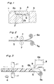
- Fig. 1 is a fragmentary cross section showing essential portions of a bearing sealing device according to one preferred embodiment of the present invention,
- Fig. 2 is a diagram for explaining a method of applying an adhesive material layer on a sealing material,
- Fig. 3 is a diagram similar to Fig. 2, which particularly shows another method therefor,
- Fig. 4 is a fragmentary cross section showing essential portions of a bearing sealing device according to a modification of the present invention,
- Fig. 5 is a fragmentary cross section showing essential portions of a bearing sealing device according to another modification of the present invention,
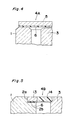
- Fig. 6 is a fragmentary cross section showing essential portions of a bearing sealing device according to a further modification of the present invention,
- Fig. 7 is a fragmentary cross section showing essential portions of a bearing sealing device according to still another modification of the present invention,
- Fig. 8 is a fragmentary cross section showing essential portions of a bearing sealing device according to a further modification of the present invention, and
- Figs. 9(A) and 9(B) are fragmentary cross sections for explaining another method of mounting the bearing sealing plate according to the present invention.
- Before the description of the present invention proceeds, it is to be noted that like parts are designated by like references numerals throughout the accompanying drawings.
- Referring now to the drawings, there is shown in Fig. 1, a sealing device for a bearing according to one preferred embodiment of the present invention, which generally includes a bearing
outer race 1 having asealing groove 2 including a vertical face 2a and ahorizontal support face 2b, a bearinginner race 3 and a bearingsealing plate 4 constituted by anadhesive material 6 applied to one or both faces of a sealingmaterial 5 having a ring-hole or not, and the bearingsealing plate 4 is bonded and fixed to the horizontal support face of said sealinggroove 2. - The bearing
sealing plate 4 is of a flat plate, and constituted by covering the surface of the sealingmaterial 5 with theadhesive material 6. The sealingmaterial 5 is made of, for example, metal, natural or synthetic rubber, plastics and the like, and is not limited in the raw material therefor so far as it is provided with air tightness. - For the
adhesive material layer 6, a material which may be bonded by heating, pressurization or known methods can be used, and although the material itself is not limited, an elastic material with adhering nature including an adhesive material of thermo-plastic property of hot-melt group is preferable. - Fig. 2 shows one embodiment of the adhering method of the
adhesive material layer 6 onto the sealingmaterial 5 for the bearingsealing plate 4, in which the sealingmaterial 5 drawn out of its roll 5a, and thatadhesive material 6 drawn out of its roll 6a respectively are passed between a set ofrollers 7 for adhesion to each other under pressure. From the belt-like sheet thus prepared by adhering theadhesive material layer 6 to the sealingmaterial 5, the bearingsealing plates 4 of a desired size are punched out by metal dies (not shown in Fig. 2). - Fig. 3 shows another method of producing the bearing
sealing plate 4. In this method, theadhesive material 6b contained in a vessel 8 is melted through heating by heating means 10, e.g., an electric heater or the like, and the moltenadhesive material 6b is discharged through a nozzle 9 of the vessel 8 onto the upper surface of the sealingmaterial 5 drawn out from aroll 5b, thereby to cause theadhesive material 6b to adhere onto the surface of the sealingmaterial 5. The belt-like sheet thus prepared is blanked bymetal dies 11 to prepare the bearingsealing plate 4. - In still another method of providing the
adhesive material layer 6 on the sealingmaterial 5, it may be so arranged to pass the sealingmaterial 5 through the moltenadhesive material 6b so as to apply theadhesive material 6b onto both surfaces of the sealingmaterial 5. - For mounting such bearing
sealing plate 4 as described so far into thesealing groove 2 in the bearingouter race 1, thesealing plate 4 is fitted into thesealing groove 2, with theadhesive material layer 6 directed downwards, and by contacting theadhesive material layer 6 with thesupport face 2b of thesealing groove 2, thesealing plate 4 is heated from above so as to melt part or all of theadhesive material layer 6, thereby to cause thesealing plate 4 to adhesive to saidsupport face 2b for subsequent cooling and fixing. (Fig. 1). - It should be noted here that the heating of the bearing
sealing plate 4 may be effected before contact with thesupport face 2b of thesealing groove 2, and that the heating means for the heating of thesealing plate 4 is not limited to any specific means. - It should also be noted that the manufacturing method of the bearing
sealing plate 4 is not limited to the above, but may, for example, be so modified as to apply the molten adhesive material onto the surface of the sealingmaterial 5 by a sprayer or by a brush. - It is further to be noted that, in the formation of the adhesive material layer on the
sealing plate 4, it may be so arranged to cause the adhering material to adhere thereto by painting, spraying or other methods after punching the sealingmaterial 5 in a desired shape. - Moreover, in the embodiment as shown in Fig. 1, it may be so modified that the
sealing groove 2 is provided on theinner race 3 instead of being formed on theouter race 1, and theadhesive material layer 6 of the bearingsealing plate 4 is brought into contact with the support face of the sealing groove of theinner race 3 for adhesion by heating. In this case, a lip may be provided on the outer peripheral edge of thesealing plate 4 so as to contact the bearingouter race 1. - In a modification as shown in Fig. 4, it is so arranged that the
sealing groove 2 is not provided on the bearingouter race 1, but thesealing plate 4A prepared by causing theadhesive material layer 6 to adhere to the sealingmaterial 5 is adapted to contact the upper surface (in Fig. 4) of the bearingouter race 1 at its side of theadhesive material layer 6, and thesealing plate 4A is heated for subsequent forced or spontaneous cooling, thereby to cause thesealing plate 4A to closely contact and to be fixed to theouter race 1. In this case, a clearance is provided between the upper surface (in Fig. 4) of theinner race 3 and theadhesive material layer 6 or thesealing material 5 as shown. - The bearing
sealing plate 4A in a flat disk-like shape may be modified to be a ring-like shape, and further, to be provided with a known lip in a peripheral edge of its inner hole (not shown). - The sealing device in Fig. 4 may be further modified in such a manner that, instead of causing the
sealing plate 4A to adhere to the surface of the bearingouter race 1, it may be adapted to adhere to theinner race 3. In that case, it may be so arranged to provide a lip at the outer peripheral edge portion of the bearing sealing plate, so that said lip contacts the bearing outer race. - The configurations of the bearing sealing plate are not limited to those as shown in Fig. 1 and Fig. 4. In the bearing
sealing plate 4B as shown in Fig. 5, the outerperipheral edge portion 13 is made of a metallic material, and its innerperipheral portion 14 is formed by an elastic material, with theadhesive material layer 6 being provided on the outerperipheral edge portion 13. Moreover, the arrangement may be so modified that the innerperipheral portion 14 is made of a metallic material and the outerperipheral portion 13 is formed by an elastic material in the reverse order as above. - In the bearing
sealing plates sealing plate 4B in Fig. 5. In thesealing plate 4A in Fig. 4, the outer peripheral edge portion and the inner portion may be formed either by a metallic material or elastic material. - The bearing sealing plate 4C as shown in Fig. 6 is of a ring-like shape, with a ring-shaped protrusion 5C being formed along an inner hole edge of the ring, and the
adhesive material layer 6 is provided on the face of the sealingmaterial 5 at its side of the protrusion 5C (excluding the under surface of the protrusion 5C) or on the outer side face of the protrusion 5C continuous on said face. The lip in the inner hole of the sealing plate 4C is abbreviated for brevity in the drawing. - In the sealing plate 4C, since the
adhesive material layer 6 is not provided on the under surface of the protrusion 5C in the ring-like shape, an unused sealing plate 4C may be overlapped therewith for storing. - Furthermore, in the sealing plate 4C, it may be so modified to place the outer peripheral portion of the sealing plate 4C on the upper surface (in Fig. 6) of the bearing
outer race 1 for use by adhering, without providing thesealing groove 2 on theouter race 1. - Moreover, in the bearing sealing plate 4C, the protrusion 5C may be provided on the outer peripheral edge of the sealing plate, instead of being provided on the ring inner hole edge.
- The bearing
sealing plate 4D as shown in Fig. 7 is of a ring-shape, and includes an outerperipheral portion 17 in a horizontal plane, anintermediate portion 18 inclined upwardly from theportion 17, and an innerhole edge portion 19 extending horizontally laterally from saidintermediate portion 17 as shown, with anadhesive material layer 6 is provided on the under surface of said outerperipheral portion 17. A lip may further be provided along the inner hole edge. - In the case where the bearing
sealing plate 4D is fitted into asealing groove 20 of a conventional bearingouter race 1 for use, after contacting theadhesive material layer 6 on the under surface of the outerperipheral portion 17 of the fittedsealing plate 4D, with the support face 20a of thesealing groove 20, thesealing plate 4D is heated, and thereafter, cooled so as to be bonded and fixed to said support face 20a. - Moreover, it may be so modified that the
bearing sealing plate 4D is bonded and fixed onto the upper surface (in Fig. 7) of the bearingouter race 1 not provided with the sealinggroove 20. In such a case, thickness (i.e., height in Fig. 7) of the bearingouter race 1 is made thinner than that of theinner race 3. - As shown in Fig. 8, it is possible to improve the sealing performance of the conventional bearing by using a conventional
outer race 1 provided with the sealinggroove 20 and a conventionalbearing sealing plate 4E, and providing theadhesive material layer 6 on the surface contacting the support face 20a of the sealinggroove 20 at the bottom face of the sealingplate 4E so as to melt theadhesive material 6 through heating for subsequent bonding and fixing. Similar effect may be obtained also with respect to the conventional construction in which the sealing groove is provided on the inner race for fitting of the bearing sealing plate. - Conventionally, in the bearing sealing plates made of metallic materials, there are available the sealing plates of curl type, root type and washer type, each of which, however, has a problem in the sealing performance. Even in the bearing sealing plates of metallic materials, the sealing performance may be improved by providing the
adhesive material layer 6 on the surfaces contacting the concave portion of the sealing groove of the outer race or the support face of the sealing groove, and by bonding the metallic sealing plate with the bearing outer race with the adhesive material. - In any of the foregoing embodiments, the layers or films may be formed through employment of the known adhesive material or elastic material with adhesive nature as the adhesive material of the
adhesive material layer 6, and the adhesive material is not limited to the thermo-plastic adhesive material. - Moreover, in any of the foregoing embodiments, it may be so arranged to cause the adhesive material to adhere to the surface of the bearing outer race or inner race contacting the sealing plate instead of subjecting the adhesive material to adhere to the sealing plate.
- Furthermore, in any of the foregoing embodiments, the adhesion between the bearing sealing plate and the bearing outer race or inner race is not limited to that by the heating method, but heating, pressurization or known methods therefor may be employed according to the nature of the adhesive material.
- Figs. 9(A) and 9(B) show another method for mounting the bearing sealing plate.
- Specifically, a sealing
groove 24 including avertical face 24a and ahorizontal support face 24b is provided on the bearingouter race 1, and aconcave portion 25 is continuously or intermittently formed on the entire surface of thevertical face 24a. - The
bearing sealing plate 4F is provided with a rather thickadhesive material layer 6F of a thermo-plastic resin formed on at least one surface of a sealingmaterial 5F. Thisadhesive material layer 6F is adapted to be slightly thicker over the entire surface or at least on the outer peripheral portion thereof. - The sealing
plate 4F is inserted into the sealinggroove 24, with theadhesive material layer 6F directed downward, and thus, theadhesive material layer 6F is caused to adhere to thesupport face 24b of the sealinggroove 24. Then, the sealingplate 4F is heated and pressurized, and part of the molten adhesive material is depressed so as to flow into theconcave portion 25 provided in thevertical face 24a and to be filled therein. Subsequently, thebearing sealing plate 6F is subjected to natural or forcible cooling or drying, thereby to solidify the adhesive material. - In the
bearing sealing plate 4F mounted in the above described method, the protruding portion 6Fa of theadhesive material layer 6F hardened in theconcave portion 25 prevents the sealingplate 4F from coming off the sealinggroove 24, thus positively maintaining the mounting strength to the bearing outer race. - It should be noted here that the arrangement may, for example, be so modified that the sealing
groove 24 is provided on theinner race 3 instead of theouter race 1, with a concave portion equivalent to theconcave portion 25 being provided in said sealing groove. In such a case, the bearing sealing plate is provided with a rather thick adhesive material layer of a thermo-plastic resin formed on at least one surface of the sealing material. This adhesive material layer is adapted to be slightly thicker over the entire surface or at least on the inner peripheral portion. In this case, the mounting method of the bearing sealing plate and formation of the protrusion of the adhesive layer and its effect, etc. are similar to those in the above arrangement. - As is clear from the foregoing description, according to the present invention, favorable effects as follows may be obtained.
- Since the constructions of the bearing sealing plate, and the sealing grooves in the bearing outer race or inner race are simple for facilitation of manufacture, less time and cost are required in the manufacture as compared with conventional arrangements.
- In the manufacture of the bearing sealing plate of the present invention, removal of burr as in the conventional arrangements is not required.
- According to the present invention, the sealing groove of the bearing outer race or inner race may be simply constituted by the vertical face and horizontal face, and the wall face of the sealing groove is not required to be curved as in the conventional constructions. Moreover, since the bearing outer race or inner race to formed with the sealing groove itself may be employed, higher strength can be achieved as compared with conventional outer race or inner race.
- In the conventional bearings, since the sealing plate is fitted into the sealing groove provided in the bearing outer race or inner race, a space is required therefor, with a consequent increase of diameter and thickness of the bearing, thus presenting a bottleneck for the size reduction of bearings. According to the present invention, however, owing to the fact that the constructions of the sealing groove of the outer race or inner face, and of the sealing plate are simplified, diameter and thickness of the bearing can be reduced for compact size of the bearing.
- When the flat sealing material is caused to adhere to the surface of the outer race or inner race without providing the sealing groove on such bearing outer race or inner race, still more compact size of the bearing may be achieved. Moreover, there is also available such an effect that in this case, particular positioning of the bearing sealing plate is not required.
- By applying the present invention to the conventional bearing outer race or inner race or to the conventional metallic bearing sealing plates and other sealing plates, sealing performance can be improved.
- In the present invention, in the case where the concave portion is provided in the vertical face of the sealing groove, and the adhesive material of the adhesive material layer is continuously directed into said concave portion to be filled therein for solidification, the hardened adhesive material in said concave portion acts as a retainer or anchor for the bearing sealing plate, thereby providing higher mounting strength of the sealing plate.
- Although the present invention has been fully described by way of example with reference to the accompanying drawings, it is to be noted here that various changes and modifications will be apparent to those skilled in the art. Therefore, unless otherwise such changes and modifications depart from the scope of the present invention, they should be construed as included therein.
Claims (8)
Applications Claiming Priority (4)
| Application Number | Priority Date | Filing Date | Title |
|---|---|---|---|
| JP324878/92 | 1992-11-10 | ||
| JP32487892 | 1992-11-10 | ||
| JP5294560A JPH06200949A (en) | 1992-11-10 | 1993-10-29 | Method for mounting sealing plate for bearing and sealing device for bearing |
| JP294560/93 | 1993-10-29 |
Publications (3)
| Publication Number | Publication Date |
|---|---|
| EP0597421A2 true EP0597421A2 (en) | 1994-05-18 |
| EP0597421A3 EP0597421A3 (en) | 1994-10-12 |
| EP0597421B1 EP0597421B1 (en) | 1999-02-10 |
Family
ID=26559886
Family Applications (1)
| Application Number | Title | Priority Date | Filing Date |
|---|---|---|---|
| EP93118080A Expired - Lifetime EP0597421B1 (en) | 1992-11-10 | 1993-11-08 | Bearing sealing device and method of mounting bearing sealing plate |
Country Status (5)
| Country | Link |
|---|---|
| US (1) | US5882121A (en) |
| EP (1) | EP0597421B1 (en) |
| JP (1) | JPH06200949A (en) |
| CN (1) | CN1054908C (en) |
| DE (1) | DE69323472T2 (en) |
Cited By (3)
| Publication number | Priority date | Publication date | Assignee | Title |
|---|---|---|---|---|
| GB2305697A (en) * | 1995-09-29 | 1997-04-16 | Michael Mcallister | In-line skate wheel cover |
| DE19900469B4 (en) * | 1998-01-08 | 2012-11-29 | Nsk Ltd. | roller bearing |
| EP3462049A1 (en) * | 2017-09-29 | 2019-04-03 | Globeride, Inc. | Magnetic fluid sealing device and magnetic fluid sealed bearing |
Families Citing this family (8)
| Publication number | Priority date | Publication date | Assignee | Title |
|---|---|---|---|---|
| US7031106B2 (en) * | 2000-02-01 | 2006-04-18 | Nsk Ltd. | Sealing member, rolling bearing, thin motor, and bearing device |
| JP2002267028A (en) * | 2001-03-07 | 2002-09-18 | Shimano Inc | Parts assembly |
| US8061903B2 (en) * | 2010-01-28 | 2011-11-22 | Rexnord Industries, Llc | Bearing assembly with extended maintenance interval |
| US8740464B2 (en) | 2011-11-02 | 2014-06-03 | Rexnord Industries, Llc | Bearing assembly having a floating seal |
| RU2608635C2 (en) | 2012-03-08 | 2017-01-23 | Везерфорд Текнолоджи Холдингз, ЛЛК | Optical converter with integrated pass element |
| WO2016145623A1 (en) * | 2015-03-18 | 2016-09-22 | The Timken Company | Fixture for installing a seal wear ring |
| DE102017107005B3 (en) | 2017-03-31 | 2018-09-13 | Schaeffler Technologies AG & Co. KG | Sealed rolling bearing |
| JP7262182B2 (en) * | 2018-05-31 | 2023-04-21 | ミネベアミツミ株式会社 | bearing device |
Citations (3)
| Publication number | Priority date | Publication date | Assignee | Title |
|---|---|---|---|---|
| GB599095A (en) * | 1945-09-13 | 1948-03-04 | Fischer Bearings Company Ltd | Improvements relating to sealed bearings |
| FR1477701A (en) * | 1966-03-10 | 1967-04-21 | Sfim | Improvements to bearings, in particular to bearings with a rotating outer ring |
| DE4135035A1 (en) * | 1991-10-23 | 1993-04-29 | Hoechst Ag | Ball bearing system - has lateral ball bearing capsule with layer of heat-resistant plastic, at right angles to the rolling axis |
Family Cites Families (2)
| Publication number | Priority date | Publication date | Assignee | Title |
|---|---|---|---|---|
| US2140672A (en) * | 1937-04-17 | 1938-12-20 | Glenn L Martin Co | Method of producing a seal |
| JPH022526U (en) * | 1988-06-16 | 1990-01-09 |
-
1993
- 1993-10-29 JP JP5294560A patent/JPH06200949A/en active Pending
- 1993-11-08 DE DE69323472T patent/DE69323472T2/en not_active Expired - Lifetime
- 1993-11-08 EP EP93118080A patent/EP0597421B1/en not_active Expired - Lifetime
- 1993-11-10 CN CN93112940A patent/CN1054908C/en not_active Expired - Fee Related
-
1997
- 1997-04-10 US US08/834,862 patent/US5882121A/en not_active Expired - Fee Related
Patent Citations (3)
| Publication number | Priority date | Publication date | Assignee | Title |
|---|---|---|---|---|
| GB599095A (en) * | 1945-09-13 | 1948-03-04 | Fischer Bearings Company Ltd | Improvements relating to sealed bearings |
| FR1477701A (en) * | 1966-03-10 | 1967-04-21 | Sfim | Improvements to bearings, in particular to bearings with a rotating outer ring |
| DE4135035A1 (en) * | 1991-10-23 | 1993-04-29 | Hoechst Ag | Ball bearing system - has lateral ball bearing capsule with layer of heat-resistant plastic, at right angles to the rolling axis |
Cited By (4)
| Publication number | Priority date | Publication date | Assignee | Title |
|---|---|---|---|---|
| GB2305697A (en) * | 1995-09-29 | 1997-04-16 | Michael Mcallister | In-line skate wheel cover |
| DE19900469B4 (en) * | 1998-01-08 | 2012-11-29 | Nsk Ltd. | roller bearing |
| EP3462049A1 (en) * | 2017-09-29 | 2019-04-03 | Globeride, Inc. | Magnetic fluid sealing device and magnetic fluid sealed bearing |
| US10451115B2 (en) | 2017-09-29 | 2019-10-22 | Globeride, Inc. | Magnetic fluid sealing device and magnetic fluid sealed bearing |
Also Published As
| Publication number | Publication date |
|---|---|
| DE69323472T2 (en) | 1999-08-05 |
| CN1054908C (en) | 2000-07-26 |
| CN1095800A (en) | 1994-11-30 |
| JPH06200949A (en) | 1994-07-19 |
| DE69323472D1 (en) | 1999-03-25 |
| US5882121A (en) | 1999-03-16 |
| EP0597421B1 (en) | 1999-02-10 |
| EP0597421A3 (en) | 1994-10-12 |
Similar Documents
| Publication | Publication Date | Title |
|---|---|---|
| EP0597421A2 (en) | Bearing sealing device and method of mounting bearing sealing plate | |
| US4459092A (en) | Apparatus for integrally molding an ornament plate on a plastic body | |
| US6066184A (en) | Voltaic cell | |
| US4595117A (en) | Sealing lip for lid on thermoformed container | |
| US4131211A (en) | Receptacle made of thermoplastic material | |
| US4228633A (en) | Method for manufacturing, filling and closing a receptacle made of thermoplastic material | |
| JPH0415091B2 (en) | ||
| CA1223532A (en) | Paper container for hot fillable liquids | |
| US4078287A (en) | Method of forming sealing members | |
| JPH10242733A (en) | Exterior component incorporating antenna for vehicle | |
| AU576740B2 (en) | An improved mounting cup and method of making same | |
| US3454692A (en) | Method of forming vehicular rearview mirrors | |
| US4659405A (en) | Method and apparatus for making a sealing lip for lid on thermoformed container | |
| EP0636820B1 (en) | Bearing sealing plate and method of manufacturing thereof | |
| US4370689A (en) | Flexible magnetic recording medium with improved reinforcement means | |
| JPH11154503A (en) | Terminal for lead-acid battery | |
| JP2956491B2 (en) | Composite lid of metal and synthetic resin and its manufacturing equipment | |
| JPH02258320A (en) | Manufacture of resin molded product with core component | |
| JPH08197648A (en) | Plastic molding with pad and its production | |
| JPS5845960Y2 (en) | Molding | |
| WO1997003807A3 (en) | Process of making b-pillar covers and covers produced thereby | |
| JPS6222026B2 (en) | ||
| JPH0564571U (en) | Sealing device | |
| JP3602982B2 (en) | Bearing seal and its manufacturing method | |
| JPH08270665A (en) | Manufacture of bearing seal |
Legal Events
| Date | Code | Title | Description |
|---|---|---|---|
| PUAI | Public reference made under article 153(3) epc to a published international application that has entered the european phase |
Free format text: ORIGINAL CODE: 0009012 |
|
| 17P | Request for examination filed |
Effective date: 19931206 |
|
| AK | Designated contracting states |
Kind code of ref document: A2 Designated state(s): DE FR GB |
|
| PUAL | Search report despatched |
Free format text: ORIGINAL CODE: 0009013 |
|
| AK | Designated contracting states |
Kind code of ref document: A3 Designated state(s): DE FR GB |
|
| 17Q | First examination report despatched |
Effective date: 19951013 |
|
| GRAG | Despatch of communication of intention to grant |
Free format text: ORIGINAL CODE: EPIDOS AGRA |
|
| GRAG | Despatch of communication of intention to grant |
Free format text: ORIGINAL CODE: EPIDOS AGRA |
|
| GRAH | Despatch of communication of intention to grant a patent |
Free format text: ORIGINAL CODE: EPIDOS IGRA |
|
| GRAH | Despatch of communication of intention to grant a patent |
Free format text: ORIGINAL CODE: EPIDOS IGRA |
|
| GRAA | (expected) grant |
Free format text: ORIGINAL CODE: 0009210 |
|
| AK | Designated contracting states |
Kind code of ref document: B1 Designated state(s): DE FR GB |
|
| ET | Fr: translation filed | ||
| REF | Corresponds to: |
Ref document number: 69323472 Country of ref document: DE Date of ref document: 19990325 |
|
| PLBE | No opposition filed within time limit |
Free format text: ORIGINAL CODE: 0009261 |
|
| STAA | Information on the status of an ep patent application or granted ep patent |
Free format text: STATUS: NO OPPOSITION FILED WITHIN TIME LIMIT |
|
| 26N | No opposition filed | ||
| REG | Reference to a national code |
Ref country code: GB Ref legal event code: IF02 |
|
| PGFP | Annual fee paid to national office [announced via postgrant information from national office to epo] |
Ref country code: GB Payment date: 20091124 Year of fee payment: 17 Ref country code: FR Payment date: 20091027 Year of fee payment: 17 |
|
| PGFP | Annual fee paid to national office [announced via postgrant information from national office to epo] |
Ref country code: DE Payment date: 20091229 Year of fee payment: 17 |
|
| GBPC | Gb: european patent ceased through non-payment of renewal fee |
Effective date: 20101108 |
|
| REG | Reference to a national code |
Ref country code: DE Ref legal event code: R119 Ref document number: 69323472 Country of ref document: DE Effective date: 20110601 Ref country code: DE Ref legal event code: R119 Ref document number: 69323472 Country of ref document: DE Effective date: 20110531 |
|
| REG | Reference to a national code |
Ref country code: FR Ref legal event code: ST Effective date: 20110801 |
|
| PG25 | Lapsed in a contracting state [announced via postgrant information from national office to epo] |
Ref country code: DE Free format text: LAPSE BECAUSE OF NON-PAYMENT OF DUE FEES Effective date: 20110531 |
|
| PG25 | Lapsed in a contracting state [announced via postgrant information from national office to epo] |
Ref country code: FR Free format text: LAPSE BECAUSE OF NON-PAYMENT OF DUE FEES Effective date: 20101130 |
|
| PG25 | Lapsed in a contracting state [announced via postgrant information from national office to epo] |
Ref country code: GB Free format text: LAPSE BECAUSE OF NON-PAYMENT OF DUE FEES Effective date: 20101108 |