EP0597052B1 - Transport robot for a machining or processing line for lead frames - Google Patents
Transport robot for a machining or processing line for lead frames Download PDFInfo
- Publication number
- EP0597052B1 EP0597052B1 EP93909739A EP93909739A EP0597052B1 EP 0597052 B1 EP0597052 B1 EP 0597052B1 EP 93909739 A EP93909739 A EP 93909739A EP 93909739 A EP93909739 A EP 93909739A EP 0597052 B1 EP0597052 B1 EP 0597052B1
- Authority
- EP
- European Patent Office
- Prior art keywords
- magazine
- transport robot
- clamping jaw
- wall
- robot according
- Prior art date
- Legal status (The legal status is an assumption and is not a legal conclusion. Google has not performed a legal analysis and makes no representation as to the accuracy of the status listed.)
- Expired - Lifetime
Links
Images


Classifications
-
- H—ELECTRICITY
- H01—ELECTRIC ELEMENTS
- H01L—SEMICONDUCTOR DEVICES NOT COVERED BY CLASS H10
- H01L21/00—Processes or apparatus adapted for the manufacture or treatment of semiconductor or solid state devices or of parts thereof
- H01L21/67—Apparatus specially adapted for handling semiconductor or electric solid state devices during manufacture or treatment thereof; Apparatus specially adapted for handling wafers during manufacture or treatment of semiconductor or electric solid state devices or components ; Apparatus not specifically provided for elsewhere
- H01L21/68—Apparatus specially adapted for handling semiconductor or electric solid state devices during manufacture or treatment thereof; Apparatus specially adapted for handling wafers during manufacture or treatment of semiconductor or electric solid state devices or components ; Apparatus not specifically provided for elsewhere for positioning, orientation or alignment
-
- H—ELECTRICITY
- H01—ELECTRIC ELEMENTS
- H01L—SEMICONDUCTOR DEVICES NOT COVERED BY CLASS H10
- H01L21/00—Processes or apparatus adapted for the manufacture or treatment of semiconductor or solid state devices or of parts thereof
- H01L21/67—Apparatus specially adapted for handling semiconductor or electric solid state devices during manufacture or treatment thereof; Apparatus specially adapted for handling wafers during manufacture or treatment of semiconductor or electric solid state devices or components ; Apparatus not specifically provided for elsewhere
- H01L21/677—Apparatus specially adapted for handling semiconductor or electric solid state devices during manufacture or treatment thereof; Apparatus specially adapted for handling wafers during manufacture or treatment of semiconductor or electric solid state devices or components ; Apparatus not specifically provided for elsewhere for conveying, e.g. between different workstations
- H01L21/67703—Apparatus specially adapted for handling semiconductor or electric solid state devices during manufacture or treatment thereof; Apparatus specially adapted for handling wafers during manufacture or treatment of semiconductor or electric solid state devices or components ; Apparatus not specifically provided for elsewhere for conveying, e.g. between different workstations between different workstations
- H01L21/67721—Apparatus specially adapted for handling semiconductor or electric solid state devices during manufacture or treatment thereof; Apparatus specially adapted for handling wafers during manufacture or treatment of semiconductor or electric solid state devices or components ; Apparatus not specifically provided for elsewhere for conveying, e.g. between different workstations between different workstations the substrates to be conveyed not being semiconductor wafers or large planar substrates, e.g. chips, lead frames
-
- B—PERFORMING OPERATIONS; TRANSPORTING
- B25—HAND TOOLS; PORTABLE POWER-DRIVEN TOOLS; MANIPULATORS
- B25J—MANIPULATORS; CHAMBERS PROVIDED WITH MANIPULATION DEVICES
- B25J15/00—Gripping heads and other end effectors
- B25J15/02—Gripping heads and other end effectors servo-actuated
- B25J15/0253—Gripping heads and other end effectors servo-actuated comprising parallel grippers
- B25J15/026—Gripping heads and other end effectors servo-actuated comprising parallel grippers actuated by gears
-
- H—ELECTRICITY
- H01—ELECTRIC ELEMENTS
- H01L—SEMICONDUCTOR DEVICES NOT COVERED BY CLASS H10
- H01L21/00—Processes or apparatus adapted for the manufacture or treatment of semiconductor or solid state devices or of parts thereof
- H01L21/67—Apparatus specially adapted for handling semiconductor or electric solid state devices during manufacture or treatment thereof; Apparatus specially adapted for handling wafers during manufacture or treatment of semiconductor or electric solid state devices or components ; Apparatus not specifically provided for elsewhere
- H01L21/683—Apparatus specially adapted for handling semiconductor or electric solid state devices during manufacture or treatment thereof; Apparatus specially adapted for handling wafers during manufacture or treatment of semiconductor or electric solid state devices or components ; Apparatus not specifically provided for elsewhere for supporting or gripping
- H01L21/687—Apparatus specially adapted for handling semiconductor or electric solid state devices during manufacture or treatment thereof; Apparatus specially adapted for handling wafers during manufacture or treatment of semiconductor or electric solid state devices or components ; Apparatus not specifically provided for elsewhere for supporting or gripping using mechanical means, e.g. chucks, clamps or pinches
- H01L21/68707—Apparatus specially adapted for handling semiconductor or electric solid state devices during manufacture or treatment thereof; Apparatus specially adapted for handling wafers during manufacture or treatment of semiconductor or electric solid state devices or components ; Apparatus not specifically provided for elsewhere for supporting or gripping using mechanical means, e.g. chucks, clamps or pinches the wafers being placed on a robot blade, or gripped by a gripper for conveyance
-
- H—ELECTRICITY
- H01—ELECTRIC ELEMENTS
- H01L—SEMICONDUCTOR DEVICES NOT COVERED BY CLASS H10
- H01L2924/00—Indexing scheme for arrangements or methods for connecting or disconnecting semiconductor or solid-state bodies as covered by H01L24/00
- H01L2924/0001—Technical content checked by a classifier
- H01L2924/0002—Not covered by any one of groups H01L24/00, H01L24/00 and H01L2224/00
Definitions
- the invention relates to a transport robot for transporting an essentially cuboid magazine for system carriers (so-called lead frames) equipped with electronic components (so-called chips) in a line of machines or devices for automatic processing or treatment of these electronic components,
- the magazine consisting essentially of consists of two parallel and spaced walls and is equipped with at least one system carrier used in compartments or grooves of its walls, and wherein the transport robot is provided with a gripping device for automatically gripping and releasing the magazine.
- the system carriers are transported from station to station in such lines.
- one or more devices for fastening the electronic components on the system carrier
- one or more devices for curing adhesives for curing ovens
- one or more devices for wire contacting are arranged in a line , with the transport of the system carriers in magazines of the type specified at the beginning.
- the system carriers are inserted laterally, but are not fastened in this direction.
- magazines of various widths, lengths and heights must be able to be handled in such a line.
- the automatic transport of the magazines is carried out by a transport robot that transports the magazines from station to station.
- Transport robots of this type are described in Solid State Technology, May 1989, pages 51-54 and in EP-A-0 412 945.
- the object of the present invention is to improve a processing line of the type mentioned above in such a way that a secure transport of the magazines or the system carriers in It is possible for the magazines that positioning errors by transport robots do not add up and that a wide variety of magazines can be taken into account.
- a transport robot of the type specified at the outset is characterized in that the gripping device has two clamping jaws which abut one side edge of a wall of the magazine and clamp this wall together when the magazine is gripped by the gripping device, being orthogonal in the direction for this clamped wall, the width of the clamping jaws is greater than the thickness of this wall.
- the magazine is no longer gripped from above and below, but from the side. This eliminates the need to lift the magazine to guide a gripper under the magazine.
- the magazine can now be conveyed on a corresponding transport surface of the processing or treatment station by means of the belt transport and, for example, be brought back into an unloading position which roughly corresponds to the loading position.
- the mutually facing sides of the two clamping jaws preferably lie essentially in mutually parallel planes, which in turn lie orthogonally to the clamped-in wall. This arrangement is optimally adapted to the essentially cuboid design of the magazine.
- the magazine In the aforementioned system of belt transport of the magazine in the processing or treatment stations, the magazine is in its loading or unloading position by the belt or belts, or better said by the friction of the magazine on or on the running belt, against a step pressed, which is higher than the floor level of the magazine and thus acts as a stop for the magazine.
- the position of the magazine is thus well defined by the fact that the magazine lies against the step.
- the gripping device can of the transport robot only reach the magazine over the step, which means that the gripping device has to move relatively high to the magazine, with the result that the lowermost system carriers in the magazine are not prevented from sliding out laterally under these circumstances.
- the gripping device of the transport robot would also have to move relatively high towards the magazine without this step in order to avoid grinding the mechanism of the gripping device on the transport surface of the processing or treatment station, again with the result that the lowermost system carriers in the magazine under these circumstances not be prevented from sliding out sideways.
- a nose is preferably formed on a lower edge of each clamping jaw, the side of which facing the other nose lies in the same plane as the corresponding plane of the clamping jaw itself, while preferably in a transport surface of a processing or treatment station of the line intended to support a magazine a recess, possibly designed as a step, for receiving the nose is formed by machines or devices.
- the tabs also overlap the lowest system carrier, so that this can also be transported safely in the magazine. For example, the magazine is first moved up to the loading position above the step and then placed on the transport surface or the transport belt, the nose engaging behind the step. The same is done in the opposite order and direction at an unloading position.
- the magazine By attacking the magazine from the side, it can have any width, height or length.
- the length of the magazine is only limited by the maximum distance between the jaws.
- the clamping jaw In order to reduce weight as much as possible, the clamping jaw should be as slim as possible, but exert a clamping effect that is as constant as possible over the entire height of the magazine. This can be guaranteed that the clamping jaws are divided into a lower strip and an upper strip of strips, a support shoulder being formed between the strip and strip of strips. This support shoulder lies in the position of use of the upper edge of the above-mentioned support strip of the gripping adapter, so that the upper strip strip, which, in contrast to the lower strip, has no abutment, can be supported against the support strip via this support shoulder.
- the gripping device is therefore preferably provided with two gripping adapters, each of which is assigned to a clamping jaw and each provided with a support strip for supporting and fastening the corresponding clamping jaw.
- the clamping jaw preferably has a clamping jaw strip which is supported and fastened on the supporting strip of the gripping adapter, and a support shoulder of a side strip projecting beyond the supporting strip and supported thereon, while the supporting strip is preferably designed as a projection protruding from a supporting surface of the gripping adapter.
- the jaw is resiliently mounted on the support bar.
- a change in the dimensions of the magazine is taken into account, for example when the magazine cools down after treatment in an oven.
- This also takes into account an inaccuracy of the magazine, for example if a magazine edge has a slope.
- a bolt arranged on the supporting strip between two spring elements engages in a cutout provided in the clamping jaw and therein against spring forces of the spring elements is movable, with a base of the cutout being positioned on the clamping jaw and the bolt on the supporting strip in such a way that there is also a distance between the clamping jaw and the supporting strip is when the bolt is pressed against the spring forces of the spring elements to the bottom of the cutout.
- the bolt forms a fulcrum for a rocker movement of the clamping jaw on the support bar.
- the clamping jaws When pressing the clamping jaws onto the side edges of the wall of the magazine, the clamping jaws first rock against the spring forces of the spring elements until they fit snugly against the side edges, then the bolt in the cutout of the clamping jaw is moved against the spring forces when the spring elements are pressed together until it hits the bottom of the cutout, but then the contact of the bolt with the base of the cutout prevents any further yielding of the clamping jaws, ie the full force of the gripper device can then act to grasp the magazine.
- the gripping device preferably has a front surface of a cover plate and the two gripping adapters each have a supporting surface, while the front surface and the two supporting surfaces lie essentially in one plane, and the front surface and essentially also the supporting surfaces in the direction orthogonal to the clamped wall thereon if the magazine is gripped by the gripping device.
- This cover plate protects a transmission mentioned below and at the same time serves as a stop for the gripping device on the wall of the magazine, so that this front surface of the cover plate forms a reference surface when the transport robot is accessed and, if necessary, also serves to move the magazine into place.
- the two gripping adapters are guided on both sides of the cover plate on counter-rotating spindles, which in turn are preferably connected to a gear, which in turn is associated with a drive.
- a symmetrical, force-controlled DC motor is selected for the drive.
- the gripping device is preferably supported via a support arm with a threaded sleeve integrated therein on a spindle arranged vertically in a column profile of the transport robot.
- This arrangement enables a lifting movement of the gripping device, which is necessary above all to compensate for different heights of the machines or devices in question for the automatic processing or treatment of electronic components, for example in order to be able to operate curing ovens arranged at different heights horizontally.
- the transport robot according to the invention can advantageously be used to transport a magazine with system carriers (so-called lead frames) for electronic components (so-called chips) in a line of machines or devices for the automatic processing or treatment of these electronic components.
- a line R of machines or devices for the automatic processing or treatment of electronic components has several processing or treatment stations connected in series one after the other (cf. FIG. 1).
- system carriers (so-called lead frames) are transported from station to station in order to be processed or treated there.
- the line R includes a device 5 (so-called die bonders) for fastening the electronic components on the system carrier, four similar devices 4 for curing adhesives (so-called curing ovens) and three similar devices 1, 2, 3 for wire contacting (so-called Wire Bonder) arranged in series one behind the other.
- a transport robot 6 which can be moved on a rail 7, magazines 8, which are equipped with system carriers, are removed from a buffer 9 and transported to the corresponding processing or treatment stations.
- the rail 7 with the transport robot 6 is positioned behind the respective processing or treatment station, so that the corresponding system carriers can be processed from the front without difficulty.
- the transport robot 6 places a magazine 8 on a transport surface 10 of a processing or treatment station, with corresponding transport belts 11 being located in the transport surface 10 and wrapping around a possibly driven deflection roller 46. 4 that a step 45 is formed in the transport surface 10, over which the magazine 8 is placed on the conveyor belts 11.
- the magazine 8 is transported to the front of the processing or treatment station by means of the conveyor belts 11.
- the system carriers 35 are removed from the magazine 8, processed or treated and then returned to the magazine 8.
- the magazine 8 is transported back by means of the conveyor belts 11 until it is pressed against the step 45 by friction on the running conveyor belts 11, which thereby acts as a stop for the magazine 8.
- the transport robot 6 In this position of the magazine 8, it can be detected by the transport robot 6 and passed on to another processing or treatment station, for example, the device 5 (so-called die bonder) for fastening the electronic components on the system carrier, a device 4 for curing of adhesives (so-called curing ovens) and a device 1, 2 or 3 for wire contacting (so-called wire bonders).
- the device 5 for fastening the electronic components on the system carrier
- a device 4 for curing of adhesives so-called curing ovens
- a device 1, 2 or 3 for wire contacting so-called wire bonders
- the transport robot 6 is seated on a carriage 13 with a housing 12, the carriage 13 being arranged to be movable on the rail 7.
- a telescopic frame 14 can be extended in the direction X from the housing 12, so that a column profile 15 can be brought close to a magazine 8 with a gripping device 16 shown in particular in FIGS. 2 and 3.
- the gripping device 16 has a support arm 17 which is guided in the column profile 15 on a spindle 18.
- a threaded sleeve 19 is placed on the spindle 18, the internal thread of which cooperates with the external thread of the spindle 18.
- a rail strip 20 is flanged to the support arm 17, on which a gear 21 for rotating two spindle rods 22 and 23 arranged in mirror image is fixed.
- the gear 21 is covered by a cover plate 24.
- the gear 21 is also assigned a drive 25, which is indicated in FIG. 2 below the gear 21, wherein corresponding gear elements transmit a rotation of a drive shaft to the gear and the gear 21 converts this rotation into a rotation of the spindle rods 22 and 23.
- the spindle 18 is also assigned a corresponding drive 26, through which the spindle 18 is rotated, the threaded sleeve 19 and then the support arm 17 or the gripping device 16 moving in the direction of the double arrow Z.
- each gripping adapter 26 On each spindle rod 22 and 23 there is a gripping adapter 26 which is guided both on the spindle rods 22 and 23 and on the rail strip 20. Upon rotation of the spindle rods 22 and 23, which takes place in opposite directions, each gripping adapter 26 is moved in the direction of the double arrow Y. The spindle rods 22 and 23 thus form two counter-rotating spindle drives with the gripping adapters 26. An outer end position of the gripping adapter 26 is indicated by dashed or dash-dotted lines.
- a front surface 27 of the gripping adapter 26 lies in a plane of a front surface 28 of the cover plate 24. Protruding beyond this front surface 27, support strips 29 are formed on each side of the adapters 26 and hold clamping jaws 30. The clamping jaws 30 are connected to the support strips 29 by means of corresponding screws 31.
- the activity of the gripping device 16 is clearly shown in FIG. 4.
- the magazines 8 generally consist of a front wall 32 and a rear wall 33. Both walls 32 and 33 are held parallel and at a distance from one another by means of threaded bolts 34, the threaded bolts 34 being able, for example, to place spacer sleeves between the two walls 32 and 33.
- System supports 35 are arranged between front wall 32 and rear wall 33 and can be accommodated in corresponding compartments or grooves, for example.
- the magazine 8 is gripped and gripped for transportation by the gripping device 16 in such a way that the clamping jaws 30 hold the rear wall 33 between them from both sides and hold them in a clamping manner.
- this transport surface 10 is formed on both sides of a recess, for example, designed as a step 45, which is provided by the nose 36 both when the magazine 8 is parked and when it is turned off Attacked recording becomes.
- a ledge 39 adjoins the lug 36 and is used to abut the support ledge 29. Holes 40 for the screws 31 are also provided in this strip 39.
- the clamping jaw is spread to form a free strip strip 42, forming a support shoulder 41, which tapers conically upwards.
- the support shoulder 41 strikes in the position of use on the upper edge of the support strip 29, whereby the strip strip 42 is supported. Therefore, when the clamping jaw 30 is clamped against the magazine 8, it cannot deflect outwards. As a result, the magazine 8 is held securely.
- the clamping jaws are resilient.
- a corresponding clamping jaw 30a takes a variable distance e from a corresponding support bar 29a against the spring force of two spring elements 47a and 47b.
- the spring elements 47a and 47b consist, for example, of packages of disc springs, i.e. so-called spring packs. Changes and inaccuracies in the dimensions of the magazine can thereby be taken into account by cushioning the clamping jaw 30a.
- a bolt 49 is arranged on the support bar 29a between the two spring elements 47a and 47b, while a cutout 50 is provided on the jaw 30a, in which the bolt 49 engages, wherein it can be moved against spring forces of the spring elements.
- the cutout 50 has a base 51 up to which the bolt 49 can be pressed against the spring force of the two spring elements 47a and 47b.
- the base 51 of the cutout 50 is positioned on the clamping jaw 30a and the bolt 49 on the support strip 29a in such a way that an average distance e shown in FIG. 6 is maintained between the clamping jaw 30a and the support strip 29a even when the bolt 49 is pressed against the spring force of the two spring elements 47a and 47b up to the base 51 of the cutout 50.
- the bolt 49 forms a fulcrum for a rocker movement of the clamping jaw 30a on the support bar 29a, which contributes to taking into account the changes and inaccuracies in the dimensions of the magazine.
- the clamping jaws 30a When pressing the two clamping jaws 30a on both sides onto the side edges of the wall of the magazine, the clamping jaws 30a first rock against the spring forces of the spring elements 47a and 47b until they lie snugly against the side edges of the magazine.
- the bolt in the cutout 50 is then moved against the spring forces when the spring elements 47a and 47b are further compressed until it rests on the base 51 of the cutout 50. Thereafter, however, the contact of the bolt 49 with the base 51 of the cutout 50 prevents any further yielding of the clamping jaws 30a, so that the full force of the gripper device is transmitted to the clamping jaws 30a and acts to grip the magazine.
- a significant advantage of this measure is that, for example, when the magazine 8 is picked up from a furnace, the magazine 8 is contracted. For this reason, the bolt 49 is not in the rest position at the base 51 of the cutout 50, but at a distance of, for example, two millimeters from it. When magazine 8 is taken up, this rest position distance is first reduced to zero. If the magazine 8 cools down, it does not fall down between the two clamping jaws 30a, because thanks to the spring-back of the spring elements 47a and 47b, these follow the changes in the dimensions of the magazine 8.
Abstract
Description
Die Erfindung betrifft einen Transportroboter zum Transport eines im wesentlichen quaderförmigen Magazins für mit elektronischen Bauelementen (sogenannten Chips) bestückte systemträger (sogenannte Leadframes) in einer Linie von Maschinen bzw. Einrichtungen zur automatischen Bearbeitung bzw. Behandlung dieser elektronischen Bauelemente, wobei das Magazin im wesentlichen aus zwei einander parallelen und im Abstand voneinander gehaltenen Wänden besteht und mit mindestens einem in Fächern oder Nuten seiner Wände eingesetzten Systemträgern bestückt ist, und wobei der Transportroboter mit einer Greifeinrichtung zum automatischen Fassen und Loslassen des Magazins versehen ist.The invention relates to a transport robot for transporting an essentially cuboid magazine for system carriers (so-called lead frames) equipped with electronic components (so-called chips) in a line of machines or devices for automatic processing or treatment of these electronic components, the magazine consisting essentially of consists of two parallel and spaced walls and is equipped with at least one system carrier used in compartments or grooves of its walls, and wherein the transport robot is provided with a gripping device for automatically gripping and releasing the magazine.
Bei der Verarbeitung von aus Halbleiterscheiben (sogenannten Wafers) herausgetrennten einzelnen elektronischen Bauelementen (sogenannten Chips) zu einem gebrauchsfertigen Zustand, der ihren industriellen Einsatz in elektronischen Schaltungen erlaubt, besteht seit langem ein Bedarf für Qualitätssteigerung und Prozess-Optimierung. Dieser Bedarf führte dazu, ganze Linien von Maschinen bzw. Einrichtungen zur automatischen Bearbeitung bzw. Behandlung dieser elektronischen Bauelemente aufzustellen und einzusetzen. Dabei werden die zunächst auf Systemträger (sogenannte Leadframes) angebrachten elektronischen Bauelemente (sogenannten Chips) auf diesen Systemträgern weiterverarbeitet.There has long been a need for quality improvement and process optimization when processing individual electronic components (so-called chips) cut out of semiconductor wafers to give them a ready-to-use state that allows their industrial use in electronic circuits. This requirement led to the establishment and use of entire lines of machines or devices for automatic processing or treatment of these electronic components. The electronic components (so-called chips) initially attached to system carriers (so-called lead frames) are further processed on these system carriers.
In derartigen Linien werden die Systemträger von Station zu Station transportiert. Beispielsweise sind eine oder mehrere Einrichtungen (sogenannte Die Bonder) zur Befestigung der elektronischen Bauelemente auf dem Systemträger, eine oder mehrere Einrichtungen zur Aushärtung von Klebstoffen (sogenannte Curing-öfen) und eine oder mehrere Einrichtungen zur Drahtkontaktierung (sogenannte Wire Bonder) in einer Linie angeordnet, wobei der Transport der Systemträger in Magazinen der eingangs angegebenen Art erfolgt. In solchen Magazinen sind die Systemträger seitlich eingeschoben, jedoch in dieser Einschubrichtung nicht befestigt.The system carriers are transported from station to station in such lines. For example, one or more devices (so-called die bonders) for fastening the electronic components on the system carrier, one or more devices for curing adhesives (so-called curing ovens) and one or more devices for wire contacting (so-called wire bonders) are arranged in a line , with the transport of the system carriers in magazines of the type specified at the beginning. In such magazines, the system carriers are inserted laterally, but are not fastened in this direction.
In Abhängigkeit der bearbeiteten Systemträger müssen in einer solchen Linie Magazine unterschiedlichster Breite, Länge und Höhe gehandhabt werden können. Der automatische Transport der Magazine wird durch einen Transportroboter bewerkstelligt, welcher die Magazine von Station zu Station transportiert.Depending on the processed system carrier, magazines of various widths, lengths and heights must be able to be handled in such a line. The automatic transport of the magazines is carried out by a transport robot that transports the magazines from station to station.
Transportroboter dieser Art sind in Solid State Technology, May 1989, Seiten 51-54 und in EP-A-0 412 945 beschrieben.Transport robots of this type are described in Solid State Technology, May 1989, pages 51-54 and in EP-A-0 412 945.
Bestimmte bisherige Transportroboter weisen eine Greifeinrichtung auf, mit der ein Magazin oben und unten von entsprechenden Greifern gefasst wird. Dies hat den erheblichen Nachteil, dass die Systemträger aus dem Magazin seitlich herausgleiten, sobald der Transportroboter mit Schwung bzw. ansehnlicher Beschleunigung eine horizontale Bewegung parallel zur Einschubrichtung der Systemträger ausführt.Certain previous transport robots have a gripping device with which a magazine is gripped by appropriate grippers at the top and bottom. This has the considerable disadvantage that the system carriers slide out of the magazine from the side as soon as the transport robot executes a horizontal movement with momentum or considerable acceleration parallel to the insertion direction of the system carriers.
Ein weiterer Nachteil ist, dass die Magazine zum Fassen und Greifen angehoben werden müssen oder aber sich über Ausnehmungen befinden, damit der untere Greifer unter das Magazin greifen kann.Another disadvantage is that the magazines have to be lifted for gripping and gripping or are located above recesses so that the lower gripper can reach under the magazine.
Ferner sind es nicht dieselben Kanten eines Magazins, die an den Bearbeitungs- bzw. Behandlungsstationen in Ladeposition und Entladeposition des Magazins als Referenzkante für den Transportroboter wirken, so dass die Greifer bisheriger Transportroboter das Magazin an einer anderen Stelle beim Wiederaufnehmen angreifen als beim Abladen. Hierdurch addieren sich die Positionierfehler des Transportroboters, und das Magazin wird bei der nächsten Bearbeitungs- bzw. Behandlungsstation an eine verschobene Position versetzt, so dass schliesslich der Transport des Magazins gefährdet ist, vor allem bei dem heute verwendeten System des Riementransportes des Magazins an bzw. in den Bearbeitungs- bzw. Behandlungsstationen selbst.Furthermore, it is not the same edges of a magazine that act at the processing or treatment stations in the loading position and unloading position of the magazine as a reference edge for the transport robot, so that the grippers of previous transport robots attack the magazine at a different location than when unloading it. As a result, the positioning errors of the transport robot add up, and the magazine is moved to a shifted position at the next processing or treatment station, so that the transport of the magazine is endangered, especially in the system of belt transport of the magazine used today or in the processing or treatment stations themselves.
Aufgabe der vorliegenden Erfindung ist es, eine Bearbeitungslinie der obengenannten Art so zu verbessern, dass ein gesicherter Transport der Magazine bzw. der Systemträger in den Magazinen möglich ist, dass sich Positionierfehler von Transportrobotern nicht addieren, und dass unterschiedlichsten Magazinen Rechnung getragen werden kann.The object of the present invention is to improve a processing line of the type mentioned above in such a way that a secure transport of the magazines or the system carriers in It is possible for the magazines that positioning errors by transport robots do not add up and that a wide variety of magazines can be taken into account.
Zur Lösung dieser Aufgabe ist ein Transportroboter der eingangs angegebenen Art dadurch gekennzeichnet, dass die Greifeinrichtung zwei Klemmbacken aufweist, die an je einer Seitenkante einer Wand des Magazins anliegen und zusammen diese Wand einklemmen, wenn das Magazin von der Greifeinrichtung gefasst ist, wobei in Richtung orthogonal zu dieser eingeklemmten Wand eine Breite der Klemmbacken grösser ist als die Dicke dieser Wand.To achieve this object, a transport robot of the type specified at the outset is characterized in that the gripping device has two clamping jaws which abut one side edge of a wall of the magazine and clamp this wall together when the magazine is gripped by the gripping device, being orthogonal in the direction for this clamped wall, the width of the clamping jaws is greater than the thickness of this wall.
Dies bedeutet, dass die Klemmbacken beiderseits in die lichte Weite des Magazins einragen, so dass die Systemträger seitlich nicht mehr aus dem Magazin herausgleiten können.This means that the clamping jaws protrude on both sides into the clear width of the magazine, so that the system carriers can no longer slide out of the magazine from the side.
Dies bedeutet auch, dass das Magazin nicht mehr von oben und unten, sondern von der Seite her gefasst wird. Damit entfällt ein Anheben des Magazins, um einen Greifer unter das Magazin zu führen. Das Magazin kann jetzt auf einer entsprechenden Transportfläche der Bearbeitungs- bzw. Behandlungsstation mittels des Riementransports gefördert werden und beispielsweise wieder in eine Entladeposition gebracht werden, die in etwa der Ladeposition entspricht.This also means that the magazine is no longer gripped from above and below, but from the side. This eliminates the need to lift the magazine to guide a gripper under the magazine. The magazine can now be conveyed on a corresponding transport surface of the processing or treatment station by means of the belt transport and, for example, be brought back into an unloading position which roughly corresponds to the loading position.
Vorzugsweise liegen dabei die einander zugewandten Seiten der beiden Klemmbacken im wesentlichen in einander parallelen Ebenen, welche ihrerseits orthogonal zur eingeklemmten Wand liegen. Diese Anordnung ist optimal an die im wesentlichen quaderförmigen Ausbildung des Magazins angepasst.The mutually facing sides of the two clamping jaws preferably lie essentially in mutually parallel planes, which in turn lie orthogonally to the clamped-in wall. This arrangement is optimally adapted to the essentially cuboid design of the magazine.
Bei dem bereits erwähnten System des Riementransportes des Magazins in den Bearbeitungs- bzw. Behandlungsstationen wird das Magazin in seiner Lade- oder Entladeposition durch den bzw. die Riemen, besser gesagt durch die Reibung des Magazins am bzw. an den laufenden Riemen, gegen eine Stufe gedrückt, die höher als die Bodenebene des Magazins liegt und dadurch als Anschlag für das Magazin wirkt. Somit wird die Position des Magazins durch das Anliegen des Magazins an der Stufe gut definiert. Dabei kann jedoch die Greifeinrichtung des Transportroboters nur über die Stufe hinweg zum Magazin gelangen, was bedeutet, dass die Greifeinrichtung relativ hoch an das Magazin heranfahren muss mit der Folge, dass die im Magazin untersten Systemträger unter diesen Umständen nicht am seitlichen Herausgleiten gehindert werden.In the aforementioned system of belt transport of the magazine in the processing or treatment stations, the magazine is in its loading or unloading position by the belt or belts, or better said by the friction of the magazine on or on the running belt, against a step pressed, which is higher than the floor level of the magazine and thus acts as a stop for the magazine. The position of the magazine is thus well defined by the fact that the magazine lies against the step. However, the gripping device can of the transport robot only reach the magazine over the step, which means that the gripping device has to move relatively high to the magazine, with the result that the lowermost system carriers in the magazine are not prevented from sliding out laterally under these circumstances.
Übrigens müsste die Greifeinrichtung des Transportroboters auch ohne diese Stufe relativ hoch an das Magazin heranfahren, um ein Schleifen des Mechanismus der Greifeinrichtung auf der Transportfläche der Bearbeitungs- bzw. Behandlungsstation zu vermeiden, wiederum mit der Folge, dass die im Magazin untersten Systemträger unter diesen Umständen nicht am seitlichen Herausgleiten gehindert werden.Incidentally, the gripping device of the transport robot would also have to move relatively high towards the magazine without this step in order to avoid grinding the mechanism of the gripping device on the transport surface of the processing or treatment station, again with the result that the lowermost system carriers in the magazine under these circumstances not be prevented from sliding out sideways.
Zur Abhilfe ist vorzugsweise an einem unteren Rand jeder Klemmbacke eine Nase angeformt, deren der anderen Nase zugewandte Seite in derselben Ebene liegt wie die entsprechende Ebene der Klemmbacke selbst, während vorzugsweise in eine zur Abstützung eines Magazins bestimmten Transportfläche einer Bearbeitungs- bzw. Behandlungsstation der Linie von Maschinen bzw. Einrichtungen eine gegebenenfalls als Stufe ausgebildete Ausnehmung zur Aufnahme der Nase eingeformt ist. Die Nasen übergreifen dann in jedem Fall auch den untersten Systemträger, so dass auch dieser gesichert im Magazin transportiert werden kann. Beispielsweise wird das Magazin zum Aufsetzen an einer Ladeposition zunächst über der Stufe herangefahren und dann auf die Transportfläche bzw. den Transportriemen abgesetzt, wobei die Nase die Stufe hintergreift. Entsprechendes erfolgt in entgegengesetzer Reihenfolge und Richtung an einer Entladeposition.To remedy this, a nose is preferably formed on a lower edge of each clamping jaw, the side of which facing the other nose lies in the same plane as the corresponding plane of the clamping jaw itself, while preferably in a transport surface of a processing or treatment station of the line intended to support a magazine a recess, possibly designed as a step, for receiving the nose is formed by machines or devices. In any case, the tabs also overlap the lowest system carrier, so that this can also be transported safely in the magazine. For example, the magazine is first moved up to the loading position above the step and then placed on the transport surface or the transport belt, the nose engaging behind the step. The same is done in the opposite order and direction at an unloading position.
Durch den Angriff des Magazins von der Seite her kann dieses eine beliebige Breite, Höhe oder Länge haben. Die Länge des Magazins wird lediglich von dem maximalen Abstand der Klemmbacken voneinander begrenzt.By attacking the magazine from the side, it can have any width, height or length. The length of the magazine is only limited by the maximum distance between the jaws.
Zur möglichst weitgehenden Gewichtsreduzierung sollte die Klemmbacke möglichst schlank ausgebildet sein, aber über die gesamte Höhe des Magazins eine möglichst gleichbleibende Klemmwirkung ausüben. Dies kann dadurch gewährleistet werden, dass die Klemmbacken in eine untere Leiste und einen oberen Leistenstreifen aufgeteilt sind, wobei zwischen Leiste und Leistenstreifen eine Auflageschulter ausgeformt ist. Diese Auflageschulter liegt in Gebrauchslage der oberen Kante der oben erwähnten Stützleiste des Greifadapters auf, so dass sich der obere Leistenstreifen, der im Gegensatz zur unteren Leiste kein Widerlager besitzt, über diese Auflageschulter gegen die Stützleiste abstützen kann.In order to reduce weight as much as possible, the clamping jaw should be as slim as possible, but exert a clamping effect that is as constant as possible over the entire height of the magazine. This can be guaranteed that the clamping jaws are divided into a lower strip and an upper strip of strips, a support shoulder being formed between the strip and strip of strips. This support shoulder lies in the position of use of the upper edge of the above-mentioned support strip of the gripping adapter, so that the upper strip strip, which, in contrast to the lower strip, has no abutment, can be supported against the support strip via this support shoulder.
Zu diesem Zweck ist daher die Greifeinrichtung vorzugsweise mit zwei Greifadaptern versehen, die je einer Klemmbacke zugeordnet und mit je einer Stützleiste zur Abstütztung und Befestigung der entsprechenden Klemmbacke versehen sind. Dabei weist die Klemmbacke vorzugsweise eine an der Stützleiste des Greifadapters abgestützte und befestigte Klemmbackenleiste sowie eine die Stützleiste übergreifende und daran abgestützte Auflageschulter eines die Stützleiste überragenden Seitenstreifens auf, während die Stützleiste vorzugsweise als aus einer Tragfläche des Greifadapters herausragender Vorsprung ausgebildet ist.For this purpose, the gripping device is therefore preferably provided with two gripping adapters, each of which is assigned to a clamping jaw and each provided with a support strip for supporting and fastening the corresponding clamping jaw. In this case, the clamping jaw preferably has a clamping jaw strip which is supported and fastened on the supporting strip of the gripping adapter, and a support shoulder of a side strip projecting beyond the supporting strip and supported thereon, while the supporting strip is preferably designed as a projection protruding from a supporting surface of the gripping adapter.
In einem bevorzugten Ausführungsbeispiel der Erfindung ist die Klemmbacke an der Stützleiste federnd gelagert. Durch diese federnde Lagerung wird einer Änderung der Abmessungen des Magazins beispielsweise beim Abkühlen desselben nach einer Behandlung in einem Ofen Rechnung getragen. Auch einer Ungenauigkeit des Magazins wird dadurch Rechnung getragen, beispielsweise wenn eine Magazinkante eine Schräge aufweist.In a preferred embodiment of the invention, the jaw is resiliently mounted on the support bar. As a result of this resilient mounting, a change in the dimensions of the magazine is taken into account, for example when the magazine cools down after treatment in an oven. This also takes into account an inaccuracy of the magazine, for example if a magazine edge has a slope.
Um dennoch einen beliebig gewünschten Anpressdruck der Klemmbacken auf die Seitenkanten der von der Greifereinrichtung gefassten Wand des Magazins zu gewährleisten, kann vorzugsweise vorgesehen werden, dass ein an der Stützleiste zwischen zwei Federelementen ortsfest angeordneter Bolzen in einen in der Klemmbacke vorgesehenen Ausschnitt eingreift und darin gegen Federkräfte der Federelemente bewegbar ist, wobei ein Grund des Ausschnitts so an der Klemmbacke und der Bolzen so an der Stützleiste positioniert ist, dass zwischen der Klemmbacke und der Stützleiste auch dann ein Abstand vorhanden ist, wenn der Bolzen gegen die Federkräfte der Federelemente bis an den Grund des Ausschnitts angedrückt ist. Durch diese Massnahme bildet der Bolzen einen Drehpunkt für eine Wippenbewegung der Klemmbacke an der Stützleiste. Beim Anpressen der Klemmbacken auf die Seitenkanten der Wand des Magazins wippen zunächst die Klemmbacken gegen die Federkräfte der Federelemente, bis sie an den Seitenkanten satt anliegen, dann wird der Bolzen im Ausschnitt der Klemmbacke gegen die Federkräfte beim Zusammendrücken der Federelemente bewegt, bis er am Grund des Ausschnitts anliegt, danach aber verhindert der Kontakt des Bolzens mit dem Grund des Ausschnitts jedes weitere Nachgeben der Klemmbacken, d.h. die volle Kraft der Greifereinrichtung kann dann zum Fassen des Magazins wirken.In order to ensure that the clamping jaws are pressed against the side edges of the wall of the magazine that is gripped by the gripper device, it can preferably be provided that a bolt arranged on the supporting strip between two spring elements engages in a cutout provided in the clamping jaw and therein against spring forces of the spring elements is movable, with a base of the cutout being positioned on the clamping jaw and the bolt on the supporting strip in such a way that there is also a distance between the clamping jaw and the supporting strip is when the bolt is pressed against the spring forces of the spring elements to the bottom of the cutout. As a result of this measure, the bolt forms a fulcrum for a rocker movement of the clamping jaw on the support bar. When pressing the clamping jaws onto the side edges of the wall of the magazine, the clamping jaws first rock against the spring forces of the spring elements until they fit snugly against the side edges, then the bolt in the cutout of the clamping jaw is moved against the spring forces when the spring elements are pressed together until it hits the bottom of the cutout, but then the contact of the bolt with the base of the cutout prevents any further yielding of the clamping jaws, ie the full force of the gripper device can then act to grasp the magazine.
Im übrigen weisen vorzugsweise die Greifeinrichtung eine Frontfläche einer Abdeckplatte und die beiden Greifadapter je eine Tragfläche auf, während die Frontfläche und die beiden Tragflächen im wesentlichen in einer Ebene liegen, und die Frontfläche sowie im wesentlichen auch die Tragflächen in Richtung orthogonal zur eingeklemmten Wand an dieser anliegen, wenn das Magazin von der Greifeinrichtung gefasst ist.Otherwise, the gripping device preferably has a front surface of a cover plate and the two gripping adapters each have a supporting surface, while the front surface and the two supporting surfaces lie essentially in one plane, and the front surface and essentially also the supporting surfaces in the direction orthogonal to the clamped wall thereon if the magazine is gripped by the gripping device.
Diese Abdeckplatte schützt ein weiter unten erwähntes Getriebe und dient gleichzeitig als Anschlag der Greifeinrichtung an der Wand des Magazins, so dass diese Frontfläche der Abdeckplatte eine Referenzfläche beim Zugreifen des Transportroboters bildet und nötigenfalls auch dazu dient, das Magazin zurechtzurücken.This cover plate protects a transmission mentioned below and at the same time serves as a stop for the gripping device on the wall of the magazine, so that this front surface of the cover plate forms a reference surface when the transport robot is accessed and, if necessary, also serves to move the magazine into place.
Vorzugsweise sind die beiden Greifadapter beiderseits der Abdeckplatte an gegenläufig drehbaren Spindel antrieben geführt, die ihrerseits vorzugsweise mit einem Getriebe verbunden sind, welchem seinerseits ein Antrieb zugeordnet ist.Preferably, the two gripping adapters are guided on both sides of the cover plate on counter-rotating spindles, which in turn are preferably connected to a gear, which in turn is associated with a drive.
Dies hat den Vorteil, dass wenn beispielsweise das Magazin in eine Entladeposition kommen sollte, welche von der Ladeposition abweicht, nun mittels der Frontfläche der Abdeckplatte als Referenzfläche und den seitlich geführten Greifadaptern eine Korrektur der Position des Magazins vorgenommen werden kann. Hierdurch können sich Positionierfehler des Transportroboters nicht in den einzelnen Bearbeitungs-bzw. Behandlungsstation addieren.This has the advantage that if, for example, the magazine comes into an unloading position that deviates from the loading position, the position of the magazine is now corrected using the front surface of the cover plate as a reference surface and the gripping adapters on the side can be. As a result, positioning errors of the transport robot cannot occur in the individual processing or Add treatment station.
Ein weiterer Vorteil der Kombination von Spindelantrieben und Getriebe ist, dass die Klemmkraft auch bei einem Stromausfall nicht aufgehoben wird und deshalb das Magazin auch bei einem Stromausfall nicht aus der Greifeinrichtung fallen kann. Ferner erfolgt die Klemmung des Magazins mit einer definierten Klemmkraft ohne Verkanten der Klemmbacken.Another advantage of the combination of spindle drives and gears is that the clamping force is not released even in the event of a power failure and therefore the magazine cannot fall out of the gripping device even in the event of a power failure. Furthermore, the magazine is clamped with a defined clamping force without tilting the clamping jaws.
Für den Antrieb wird beispielsweise ein symmetrischer kraftgesteuerter Gleichstrom-Motor gewählt.For example, a symmetrical, force-controlled DC motor is selected for the drive.
Vorzugsweise ist die Greifeinrichtung über einen Tragarm mit darin integrierter Gewindehülse an einer senkrecht in einem Säulenprofil des Transportroboters angeordneten Spindel abgestützt. Diese Anordnung ermöglicht eine Hubbewegung der Greifeinrichtung, die vor allem notwendig ist, um unterschiedliche Höhen der betreffenden Maschinen bzw. Einrichtungen zur automatischen Bearbeitung bzw. Behandlung von elektronischen Bauelementen auszugleichen, beispielsweise um in unterschiedlichen Höhen angeordnete Aushärtungsöfen waagrecht bedienen zu können.The gripping device is preferably supported via a support arm with a threaded sleeve integrated therein on a spindle arranged vertically in a column profile of the transport robot. This arrangement enables a lifting movement of the gripping device, which is necessary above all to compensate for different heights of the machines or devices in question for the automatic processing or treatment of electronic components, for example in order to be able to operate curing ovens arranged at different heights horizontally.
Insgesamt ist der erfindungsgemässe Transportroboter mit Vorteil zum Transport eines Magazins mit darin eingesetzten Systemträgern (sogenannten Leadframes) für elektronische Bauelemente (sogenannte Chips) in einer Linie von Maschinen bzw. Einrichtungen zur automatischen Bearbeitung bzw. Behandlung dieser elektronischen Bauelemente verwendbar.Overall, the transport robot according to the invention can advantageously be used to transport a magazine with system carriers (so-called lead frames) for electronic components (so-called chips) in a line of machines or devices for the automatic processing or treatment of these electronic components.
Eine solche Verwendung ist preisgünstig, wobei die Umrüstung von vorhandenen Transportrobotern lediglich bezüglich der Greifeinrichtung mechanisch, ansonsten nur softwaremässig zu erfolgen braucht.Such use is inexpensive, the retrofitting of existing transport robots only having to be done mechanically with respect to the gripping device, otherwise only using software.
Weitere Vorteile, Merkmale und Einzelheiten der Erfindung ergeben sich aus der nachfolgenden Beschreibung bevorzugter Ausführungsbeispiele sowie anhand der Zeichnung. Es zeigen:
- Fig. 1
- eine perspektivische Ansicht einer Linie von Maschinen bzw. Einrichtungen zur automatischen Bearbeitung bzw. Behandlung von elektronischen Bauelementen;
- Fig. 2
- eine schematisierte Draufsicht auf einen erfindungsgemässen Transportroboter;
- Fig. 3
- eine Seitenansicht des Transportroboters gemäss Fig. 2;
- Fig. 4
- eine Seitenansicht eines Teils einer Bearbeitungs-bzw. Behandlungsstation sowie eines Teils des Transportroboters gemäss Fig. 2 beim Aufsetzen eines Magazins;
- Fig. 5
- eine Seitenansicht eines Teils eines weiteren Ausführungsbeispiels eines Transportroboters;
- Fig. 6
- eine Vorderansicht des Teils des Transportroboters beim Ausführungsbeispiel gemäss Fig. 5;
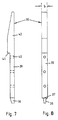
- Fig. 7
- eine Draufsicht auf eine erfindungsgemässe Klemmbacke;
- Fig. 8
- eine weitere Draufsicht auf die Klemmbacke gemäss Fig. 5, jedoch um 90° gedreht.
- Fig. 1
- a perspective view of a line of machines or devices for automatic processing or treatment of electronic components;
- Fig. 2
- a schematic plan view of an inventive transport robot;
- Fig. 3
- a side view of the transport robot according to FIG. 2;
- Fig. 4
- a side view of part of a machining or. Treatment station and part of the transport robot according to Figure 2 when placing a magazine.
- Fig. 5
- a side view of part of a further embodiment of a transport robot;
- Fig. 6
- a front view of the part of the transport robot in the embodiment of FIG. 5;
- Fig. 7
- a plan view of a jaw according to the invention;
- Fig. 8
- another plan view of the jaw according to FIG. 5, but rotated by 90 °.
Eine Linie R von Maschinen bzw. Einrichtungen zur automatischen Bearbeitung bzw. Behandlung von elektronischen Bauelementen (sogenannten Chips) weist in Reihe hintereinander geschaltet mehrere Bearbeitungs- bzw. Behandlungsstationen auf (vgl. Fig. 1). In der Linie R werden Systemträger (sogenannte Leadframes) von Station zu Station transportiert, um dort bearbeitet bzw. behandelt zu werden. Beispielsweise sind in der Linie R eine Einrichtung 5 (sogenannter Die Bonder) zur Befestigung der elektronischen Bauelemente auf dem Systemträger, vier gleichartige Einrichtungen 4 zur Aushärtung von Klebstoffen (sogenannte Curing-öfen) und drei gleichartige Einrichtungen 1, 2, 3 zur Drahtkontaktierung (sogenannte Wire Bonder) in Reihe hintereinander geschaltet angeordnet.A line R of machines or devices for the automatic processing or treatment of electronic components (so-called chips) has several processing or treatment stations connected in series one after the other (cf. FIG. 1). In line R, system carriers (so-called lead frames) are transported from station to station in order to be processed or treated there. For example, the line R includes a device 5 (so-called die bonders) for fastening the electronic components on the system carrier, four
Über einen Transportroboter 6, welcher auf einer Schiene 7 verfahrbar ist, werden Magazine 8, die mit Systemträgern bestückt sind, einem Puffer 9 entnommen und zu den entsprechenden Bearbeitungs- bzw. Behandlungsstationen transportiert. Anders als beim bisher bekannten Stand der Technik ist dabei die Schiene 7 mit dem Transportroboter 6 hinter der jeweiligen Bearbeitungs- bzw. Behandlungsstation positioniert, so dass eine Bearbeitung der entsprechenden systemträger von vorne ohne Schwierigkeiten stattfinden kann.Via a transport robot 6, which can be moved on a
Der Transportroboter 6 setzt ein Magazin 8 auf eine Transportfläche 10 einer Bearbeitungs- bzw. Behandlungsstation auf, wobei sich in der Transportfläche 10 entsprechende Transportbänder 11 befinden, welche eine gegebenenfalls angetriebene Umlenkrolle 46 umschlingen. In Fig. 4 ist erkennbar, dass in der Transportfläche 10 eine Stufe 45 eingeformt ist, über welche hinweg das Magazin 8 auf die Transportbänder 11 aufgesetzt wird. Mittels der Transportbänder 11 wird das Magazin 8 zur Vorderseite der Bearbeitungs- bzw. Behandlungsstation transportiert. Dort werden die Systemträger 35 aus dem Magazin 8 entnommen, bearbeitet bzw. behandelt und dann wieder in das Magazin 8 zurückgegeben. Danach erfolgt mittels der Transportbänder 11 ein Rücktransport des Magazins 8, bis es durch Reibung an den laufenden Transportbändern 11 gegen die Stufe 45 gedrückt wird, welche dadurch als Anschlag für das Magazin 8 wirkt. In dieser Position des Magazins 8 kann es von dem Transportroboter 6 erfasst und zu einer anderen Bearbeitungs- bzw. Behandlungsstation weitergegeben werden, um beispielsweise nacheinander die Einrichtung 5 (sogenannter Die Bonder) zur Befestigung der elektronischen Bauelemente auf dem Systemträger, eine Einrichtung 4 zur Aushärtung von Klebstoffen (sogenannte Curing-Öfen) und eine Einrichtung 1, 2 oder 3 zur Drahtkontaktierung (sogenannte Wire Bonder) durchzulaufen.The transport robot 6 places a
Der Transportroboter 6 sitzt mit einem Gehäuse 12 einem Schlitten 13 auf, wobei der Schlitten 13 auf der Schiene 7 verfahrbar angeordnet ist. Aus dem Gehäuse 12 ist ein Teleskoprahmen 14 in Richtung X ausfahrbar, so dass ein Säulenprofil 15 mit einer insbesondere in den Fig. 2 und 3 gezeigten Greifeinrichtung 16 nahe an ein Magazin 8 herangebracht werden kann.The transport robot 6 is seated on a
Dabei weist die Greifeinrichtung 16 einen Tragarm 17 auf, welcher in dem Säulenprofil 15 an einer Spindel 18 geführt ist. Auf die Spindel 18 ist eine Gewindehülse 19 aufgesetzt, deren Innengewinde mit dem Aussengewinde der Spindel 18 zusammenwirkt. Hierdurch erfolgt ein Anheben oder Absenken des Tragarmes 17 und damit der Greifeinrichtung 16 in Richtung des Doppelpfeiles Z.The
An den Tragarm 17 ist ein Schienenstreifen 20 angeflanscht, an welchem ein Getriebe 21 zum Drehen von zwei spiegelbildlich angeordneten Spindelstangen 22 und 23 festgelegt ist. Frontwärtig wird das Getriebe 21 von einer Abdeckplatte 24 abgedeckt. Dem Getriebe 21 ist im übrigen ein Antrieb 25 zugeordnet, der in Fig. 2 unterhalb des Getriebes 21 angedeutet ist, wobei entsprechende Getriebelemente eine Drehung einer Antriebswelle auf das Getriebe übertragen und das Getriebe 21 diese Drehung in eine Drehung der Spindelstangen 22 und 23 umsetzt. Es versteht sich von selbst, dass auch der Spindel 18 ein entsprechender Antrieb 26 zugeordnet ist, durch den die Spindel 18 gedreht wird, wobei sich dann die Gewindehülse 19 und mit ihr der Tragarm 17 bzw. die Greifeinrichtung 16 in Richtung des Doppelpfeiles Z bewegen.A
Auf jeder Spindelstange 22 und 23 befindet sich ein Greifadapter 26, welcher sowohl an den Spindelstangen 22 und 23 wie auch an dem Schienenstreifen 20 geführt ist. Bei Drehung der Spindelstangen 22 und 23, welche gegenläufig erfolgt, wird jeder Greifadapter 26 in Richtung des Doppelpfeiles Y bewegt. Die Spindelstangen 22 und 23 bilden also mit den Greifadaptern 26 zwei gegenläufige Spindelantriebe. Eine äussere Endlage des Greifadapters 26 ist gestrichelt bzw. strichpunktiert angedeutet.On each
Eine Frontfläche 27 des Greifadapters 26 liegt in einer Ebene einer Frontfläche 28 der Abdeckplatte 24. Über diese Frontfläche 27 hinausragend sind den Adaptern 26 jeweils seitlich Stützleisten 29 angeformt, welche Klemmbacken 30 halten. Die Klemmbacken 30 sind dabei über entsprechende Schrauben 31 mit den Stützleisten 29 verbunden.A
In Fig. 4 ist die Tätigkeit der Greifeinrichtung 16 deutlich gezeigt. Die Magazine 8 bestehen in der Regel aus einer Frontwand 32 und einer Rückwand 33. Beide Wände 32 und 33 sind über Gewindebolzen 34 parallel zueinander und im Abstand voneinander gehalten, wobei den Gewindebolzen 34 beispielsweise Abstandshülsen zwischen beiden Wänden 32 und 33 aufgesetzt sein können. Zwischen Frontwand 32 und Rückwand 33 sind Systemträger 35 angeordnet, die beispielsweise in entsprechenden Fächern oder Nuten aufgenommen sein können.The activity of the
Das Magazin 8 wird zum Transport von der Greifeinrichtung 16 so angegriffen und gefasst, dass die Klemmbacken 30 die Rückwand 33 von beiden Seiten her zwischen sich aufnehmen und klemmend halten.The
Dabei weist jede Klemmbacke 30 gemäss den Fig. 5 und 8 eine Breite b auf, welche etwas grösser ist, als die Breite b₁ der Rückwand 33. Dies gewährleistet, dass die Klemmbacke 30 mit einem Teil ihrer Breite b in die lichte Weite zwischen Frontwand 32 und Rückwand 33 einragt, so dass ein Herausfallen der Systemträger 35 aus dem Magazin 8 beim Transport vermieden wird. Eben diesem Zweck dient auch eine Nase 36, welche einem unteren Rand 37 der Klemmbacke 30 angeformt ist. Diese Nase 36 dient einem Ausgleich, wenn beispielsweise die Greifeinrichtung 16 zu hoch an dem Magazin 8 angesetzt wird. Wäre die Nase 36 nicht vorhanden, bestünde die Gefahr, dass bei einem zu hohen Ansetzen der Klemmbacken 30 an den Seitenkanten der Rückwand 33 die untersten Systemträger frei wären und aus dem Magazin 8 herausgleiten könnten. Dies wird durch die Nase 36 verhindert, welche mit ihrer Breite ebenfalls zumindest teilweise in die lichte Weite zwischen Frontwand 32 und Rückwand 33 einragt.5 and 8 has a width b , which is slightly larger than the
Damit jedoch überhaupt ein ordnungsgemässer Angriff der Greifeinrichtung 16 an dem Magazin 8 auf der Transportfläche 10 möglich ist, ist dieser Transportfläche 10 jeweils beiderseits eine beispielsweise als Stufe 45 ausgebildete Ausnehmung eingeformt, welche von der Nase 36 sowohl beim Abstellen des Magazins 8 wie auch bei dessen Aufnahme hintergriffen wird.However, so that a proper attack of the
An die Nase 36 schliesst sich nach oben eine Leiste 39 an, welche zur Anlage an die Stützleiste 29 dient. In dieser Leiste 39 sind auch Bohrungen 40 für die Schrauben 31 vorgesehen.A
Im Anschluss an die Leiste 39 ist die Klemmbacke unter Ausbildung einer Auflageschulter 41 zu einem freien Leistenstreifen 42 verbreitet, wobei diese nach oben konisch zuläuft. Die Auflageschulter 41 schlägt in Gebrauchslage auf der Oberkante der Stützleiste 29 auf, wodurch der Leistenstreifen 42 abgestützt ist. Deshalb kann dieser bei einer klemmenden Anlage der Klemmbacke 30 an das Magazin 8 nicht nach aussen ausweichen. Hierdurch wird das Magazin 8 gesichert gehalten.Following the
In einem in Fig. 5 und 6 näher dargestellten Ausführungsbeispiel der Erfindung sind die Klemmbacken federnd ausgebildet. Eine entsprechende Klemmbacke 30a nimmt dabei von einer entsprechenden Stützleiste 29a gegen die Federkraft von zwei Federelementen 47a und 47b einen variablen Abstand e ein. Die Federelemente 47a und 47b bestehen beispielsweise aus Paketen von Scheibenfedern, d.h. sogenannten Federpaketen. Dadurch kann Änderungen und Ungenauigkeiten der Abmes-sungen des Magazins durch Abfederung der Klemmbacke 30a Rechnung getragen werden.In an embodiment of the invention shown in more detail in FIGS. 5 and 6, the clamping jaws are resilient. A
Ein Bolzen 49 ist an der Stützleiste 29a zwischen den beiden Federelementen 47a und 47b ortsfest angeordnet, während an der Klemmbacke 30a ein Ausschnitt 50 vorgesehen ist, in den der Bolzen 49 eingreift, wobei er darin gegen Federkräfte der Federelemente bewegbar ist. Der Ausschnitt 50 weist einen Grund 51 auf, bis zum dem der Bolzen 49 gegen die Federkraft der beiden Federelemente 47a und 47b gedrückt werden kann. Der Grund 51 des Ausschnitts 50 ist so an der Klemmbacke 30a und der Bolzen 49 so an der Stützleiste 29a positioniert, dass zwischen der Klemmbacke 30a und der Stützleiste 29a auch dann ein in Fig. 6 eingezeichneter durchschnittlicher Abstand e eingehalten wird, wenn der Bolzen 49 gegen die Federkraft der beiden Federelemente 47a und 47b bis an den Grund 51 des Ausschnitts 50 angedrückt wird. Dadurch bildet der Bolzen 49 einen Drehpunkt für eine Wippenbewegung der Klemmbacke 30a an der Stützleiste 29a, die dazu beiträgt, den Änderungen und Ungenauigkeiten der Abmessungen des Magazins Rechnung zu tragen. Beim Anpressen der beiden Klemmbacken 30a beiderseits auf die Seitenkanten der Wand des Magazins wippen zunächst die Klemmbacken 30a gegen die Federkräfte der Federelemente 47a und 47b, bis sie an den Seitenkanten des Magazins satt anliegen. Anschliessend wird der Bolzen im Ausschnitt 50 gegen die Federkräfte beim weiteren Zusammendrücken der Federelemente 47a und 47b bewegt, bis er am Grund 51 des Ausschnitts 50 anliegt. Danach aber verhindert der Kontakt des Bolzens 49 mit dem Grund 51 des Ausschnitts 50 jedes weitere Nachgeben der Klemmbacken 30a, so dass die volle Kraft der Greifereinrichtung auf die Klemmbacken 30a übertragen wird und zum Fassen des Magazins wirkt.A bolt 49 is arranged on the
Wesentlicher Vorteil dieser Massnahme ist, dass beispielsweise bei Aufnahme des Magazins 8 aus einem Ofen einem Zusammenziehen des Magazins 8 Rechnung getragen wird. Aus diesem Grund liegt der Bolzen 49 in Ruhelage eben nicht am Grund 51 des Ausschnitts 50, sondern im Abstand von beispielsweise zwei Millimetern davon. Bei Aufnahme des Magazins 8 wird zuerst dieser Ruhelage-Abstand bis auf Null vermindert. Kühlt das Magazin 8 ab, so fällt es nicht zwischen den beiden Klemmbacken 30a herab, weil diese dank der Zurückfederung der Federelemente 47a und 47b den Änderungen der Dimensionen des Magazins 8 folgen.A significant advantage of this measure is that, for example, when the
Claims (12)
- Transport robot for transporting an essentially cuboidal magazine (8) for lead frames (35) fitted with electronic chips in a line of machines or devices for the automatic processing or treatment of these electronic chips, the magazine essentially comprising two walls (32, 33) kept parallel to each other and at a distance from each other and being fitted with at least one lead frame (35) inserted in compartments or grooves of its walls (32, 33), and the transport robot being provided with a gripping device (16) for the automatic grasping and releasing of the magazine (8), characterized in that the gripping device (16) has two clamping jaws (30; 30a) which bear against one side edge each of a wall (33) of the magazine (8) and together clamp this wall (33) when the magazine (8) is grasped by the gripping device (16), a width (b) of the clamping jaws (30; 30a) in a direction orthogonal to this clamped-in wall (33) being greater than the thickness (b₁) of this wall (33), the clamping jaws on both sides protruding into the clear widths of the magazine, so that the lead frames can no longer slide out laterally from the magazine.
- Transport robot according to Claim 1, characterized in that mutually facing sides of the two clamping jaws (30; 30a) lie essentially in planes parallel to each other, which for their part lie orthogonally to the clamped-in wall (33).
- Transport robot according to Claim 2, characterized in that the gripping device (16) is provided with two gripping adapters (26), which are each assigned to a clamping jaw (30; 30a) and are provided with a supporting bar (29) each for supporting and fastening the corresponding clamping jaw (30; 30a).
- Transport robot according to Claim 3, characterized in that the clamping jaw (30a) is mounted resiliently on the supporting bar (29a).
- Transport robot according to Claim 4, characterized in that a bolt (49) arranged fixedly on the supporting bar (29a) between two spring elements (47a, 47b) engages in a cutout (50) provided in the clamping jaw (30a) and can be moved therein against spring forces of the spring elements (47a, 47b), a base (51) of the cutout (50) being positioned at the clamping jaw (30a) and the bolt (49) being positioned at the supporting bar (29a) in such a way that there is a distance (e) between the clamping jaw (30a) and the supporting bar (29a) even when the bolt (49) is pressed against the spring forces of the spring elements (47a, 47b) up to the base (51) of the cutout (50).
- Transport robot according to Claim 2, characterized in that there is formed on a lower rim (37) of each clamping jaw (30; 30a) a lug (36), whose side facing the other lug (36) lies in the same plane as the corresponding plane of the clamping jaw (30; 30a) itself.
- Transport robot according to Claim 3, characterized in that the gripping device (16) has a front surface (28) of a covering plate (24) and the two gripping adapters (26) each have a bearing surface (27), the front surface (28) and the two bearing surfaces (27) lie essentially in one plane, and the front surface (28) and also essentially the bearing surfaces (27) bear against the clamped-in wall (33) in a direction orthogonal to this wall (33) when the magazine (8) is grasped by the gripping device (16).
- Transport robot according to Claim 3, characterized in that the clamping jaw (30) has a clamping jaw bar (39), supported and fastened on the supporting bar (29) of the gripping adapter (26), and also a rest shoulder (41), engaging over the supporting bar (29) and supported thereon, of a side strip (42) rising above the supporting bar (29).
- Transport robot according to Claim 3, characterized in that the supporting bar (29) is designed as a projection rising out from a bearing surface (27) of the gripping adapter (26).
- Transport robot according to Claim 3, characterized in that the two gripping adapters (26) on both sides of the covering plate (24) are guided on oppositely rotatable spindle drives (22, 23).
- Transport robot according to Claim 8, characterized in that the spindle drives (22, 23) are connected to a gear mechanism (21), which for its part is assigned a drive (25).
- Transport robot according to Claim 1, characterized in that the gripping device (16) is supported by means of a bearing arm (17) with a threaded sleeve (19) integrated therein on a spindle (18) arranged perpendicularly in a column profile (15) of the transport robot (6).
Applications Claiming Priority (3)
| Application Number | Priority Date | Filing Date | Title |
|---|---|---|---|
| CH1785/92 | 1992-06-03 | ||
| CH178592 | 1992-06-03 | ||
| PCT/CH1993/000130 WO1993024953A1 (en) | 1992-06-03 | 1993-05-21 | Transport robot for a machining or processing line for lead frames |
Publications (2)
| Publication Number | Publication Date |
|---|---|
| EP0597052A1 EP0597052A1 (en) | 1994-05-18 |
| EP0597052B1 true EP0597052B1 (en) | 1996-04-17 |
Family
ID=4218550
Family Applications (1)
| Application Number | Title | Priority Date | Filing Date |
|---|---|---|---|
| EP93909739A Expired - Lifetime EP0597052B1 (en) | 1992-06-03 | 1993-05-21 | Transport robot for a machining or processing line for lead frames |
Country Status (8)
| Country | Link |
|---|---|
| EP (1) | EP0597052B1 (en) |
| JP (1) | JPH07503413A (en) |
| KR (1) | KR100268599B1 (en) |
| AT (1) | ATE137062T1 (en) |
| DE (1) | DE59302257D1 (en) |
| HK (1) | HK1007215A1 (en) |
| SG (1) | SG47434A1 (en) |
| WO (1) | WO1993024953A1 (en) |
Cited By (1)
| Publication number | Priority date | Publication date | Assignee | Title |
|---|---|---|---|---|
| DE102007021068A1 (en) * | 2007-05-04 | 2008-11-06 | Christian Beer | Method and device for dispensing and picking up workpieces on a working plane |
Families Citing this family (5)
| Publication number | Priority date | Publication date | Assignee | Title |
|---|---|---|---|---|
| DE29718994U1 (en) * | 1997-10-24 | 1998-02-19 | Siemens Ag | Device for gripping magazines |
| EP1143489A1 (en) * | 2000-04-04 | 2001-10-10 | ESEC Trading SA | Linear guide with an air bearing |
| SG100644A1 (en) * | 2000-04-04 | 2003-12-26 | Esec Trading Sa | Linear guide with air bearing |
| EP1143487A1 (en) * | 2000-04-04 | 2001-10-10 | ESEC Trading S.A. | Linear guide with an air bearing |
| CN108340655B (en) * | 2018-03-30 | 2023-07-14 | 青岛乾程科技股份有限公司 | Liquid crystal display dyestripping device |
Family Cites Families (2)
| Publication number | Priority date | Publication date | Assignee | Title |
|---|---|---|---|---|
| US4816732A (en) * | 1987-08-17 | 1989-03-28 | Sgs Thomson Microelectronics, Inc. | Robotic hand for transporting semiconductor wafer carriers |
| IT1235835B (en) * | 1989-08-08 | 1992-11-03 | Sgs Thomson Microelectronics | AUTOMATIC HANDLING OF DIFFERENT CONTAINERS WITH STANDARDIZED COLLECTION AND CODING POINTS |
-
1993
- 1993-05-21 SG SG1996001350A patent/SG47434A1/en unknown
- 1993-05-21 EP EP93909739A patent/EP0597052B1/en not_active Expired - Lifetime
- 1993-05-21 WO PCT/CH1993/000130 patent/WO1993024953A1/en active IP Right Grant
- 1993-05-21 AT AT93909739T patent/ATE137062T1/en not_active IP Right Cessation
- 1993-05-21 KR KR1019930703998A patent/KR100268599B1/en not_active IP Right Cessation
- 1993-05-21 JP JP6500056A patent/JPH07503413A/en active Pending
- 1993-05-21 DE DE59302257T patent/DE59302257D1/en not_active Expired - Fee Related
-
1998
- 1998-06-24 HK HK98106245A patent/HK1007215A1/en not_active IP Right Cessation
Cited By (1)
| Publication number | Priority date | Publication date | Assignee | Title |
|---|---|---|---|---|
| DE102007021068A1 (en) * | 2007-05-04 | 2008-11-06 | Christian Beer | Method and device for dispensing and picking up workpieces on a working plane |
Also Published As
| Publication number | Publication date |
|---|---|
| ATE137062T1 (en) | 1996-05-15 |
| KR940701583A (en) | 1994-05-28 |
| WO1993024953A1 (en) | 1993-12-09 |
| DE59302257D1 (en) | 1996-05-23 |
| SG47434A1 (en) | 1998-04-17 |
| JPH07503413A (en) | 1995-04-13 |
| EP0597052A1 (en) | 1994-05-18 |
| KR100268599B1 (en) | 2000-10-16 |
| HK1007215A1 (en) | 1999-04-01 |
Similar Documents
| Publication | Publication Date | Title |
|---|---|---|
| DE19906805B4 (en) | Apparatus and method for transporting substrates to be processed | |
| DE69824562T2 (en) | SYSTEM FOR TRANSPORTING WAFER FROM CASSETTE TO OVEN AND METHOD | |
| EP1114440B1 (en) | Device and method for handling individual wafers | |
| DE3608079A1 (en) | ROBOTIC SYSTEM FOR PACKING CONICAL OBJECTS | |
| WO1992002950A1 (en) | Arrangement for storing, transporting and enclosing substrates | |
| DE19616820A1 (en) | Magazine fitting frame for test manipulator for testing integrated circuit modules | |
| EP1008521A2 (en) | Device for feeding groups of piled flat products, in particular biscuits, in packaging containers | |
| EP1468942A1 (en) | Method and device for managing a warehouse | |
| EP0597052B1 (en) | Transport robot for a machining or processing line for lead frames | |
| DE102019115634B3 (en) | Sorting system for a machine tool, machine tool and method for sorting cut parts | |
| EP1177570A1 (en) | Device for handling substrates inside and outside a clean room | |
| EP1026081A2 (en) | Method and apparatus for feeding carton blanks | |
| DE4425127A1 (en) | Storage system for order picking | |
| EP1924399B1 (en) | Device for transporting workpiece holders | |
| DE3403550A1 (en) | TRANSPORT AND STORAGE RACK | |
| EP1606836A2 (en) | Gripper and method for operating the same | |
| EP2165952B1 (en) | Separation device | |
| EP2033735B1 (en) | Compact workpiece changer | |
| EP3782933A1 (en) | Container stacking picking cart | |
| DE102019007755B4 (en) | Hard disk handling device | |
| EP0500525A1 (en) | Device for drilling printed circuit boards. | |
| EP0240812B1 (en) | Storing system | |
| DE19517295A1 (en) | Feed system to separation unit for plate shaped components | |
| DE3203757A1 (en) | Apparatus for the intermediate stacking of articles | |
| WO2000005772A1 (en) | Method and device for processing a flat workpiece, especially a semiconductor wafer |
Legal Events
| Date | Code | Title | Description |
|---|---|---|---|
| PUAI | Public reference made under article 153(3) epc to a published international application that has entered the european phase |
Free format text: ORIGINAL CODE: 0009012 |
|
| 17P | Request for examination filed |
Effective date: 19931126 |
|
| AK | Designated contracting states |
Kind code of ref document: A1 Designated state(s): AT BE CH DE DK ES FR GB GR IE IT LI LU MC NL PT SE |
|
| 17Q | First examination report despatched |
Effective date: 19950710 |
|
| GRAH | Despatch of communication of intention to grant a patent |
Free format text: ORIGINAL CODE: EPIDOS IGRA |
|
| GRAA | (expected) grant |
Free format text: ORIGINAL CODE: 0009210 |
|
| AK | Designated contracting states |
Kind code of ref document: B1 Designated state(s): AT BE CH DE DK ES FR GB GR IE IT LI LU MC NL PT SE |
|
| PG25 | Lapsed in a contracting state [announced via postgrant information from national office to epo] |
Ref country code: IT Free format text: LAPSE BECAUSE OF FAILURE TO SUBMIT A TRANSLATION OF THE DESCRIPTION OR TO PAY THE FEE WITHIN THE PRE;WARNING: LAPSES OF ITALIAN PATENTS WITH EFFECTIVE DATE BEFORE 2007 MAY HAVE OCCURRED AT ANY TIME BEFORE 2007. THE CORRECT EFFECTIVE DATE MAY BE DIFFERENT FROM THE ONE RECORDED.SCRIBED TIME-LIMIT Effective date: 19960417 Ref country code: GR Free format text: LAPSE BECAUSE OF FAILURE TO SUBMIT A TRANSLATION OF THE DESCRIPTION OR TO PAY THE FEE WITHIN THE PRESCRIBED TIME-LIMIT Effective date: 19960417 Ref country code: ES Free format text: THE PATENT HAS BEEN ANNULLED BY A DECISION OF A NATIONAL AUTHORITY Effective date: 19960417 Ref country code: DK Effective date: 19960417 Ref country code: BE Effective date: 19960417 |
|
| REF | Corresponds to: |
Ref document number: 137062 Country of ref document: AT Date of ref document: 19960515 Kind code of ref document: T |
|
| REG | Reference to a national code |
Ref country code: CH Ref legal event code: NV Representative=s name: R. A. EGLI & CO. PATENTANWAELTE |
|
| REG | Reference to a national code |
Ref country code: IE Ref legal event code: FG4D Free format text: 68003 |
|
| PG25 | Lapsed in a contracting state [announced via postgrant information from national office to epo] |
Ref country code: AT Effective date: 19960521 |
|
| REF | Corresponds to: |
Ref document number: 59302257 Country of ref document: DE Date of ref document: 19960523 |
|
| PG25 | Lapsed in a contracting state [announced via postgrant information from national office to epo] |
Ref country code: MC Effective date: 19960531 Ref country code: LU Free format text: LAPSE BECAUSE OF NON-PAYMENT OF DUE FEES Effective date: 19960531 |
|
| RAP2 | Party data changed (patent owner data changed or rights of a patent transferred) |
Owner name: ESEC SA |
|
| GBT | Gb: translation of ep patent filed (gb section 77(6)(a)/1977) |
Effective date: 19960509 |
|
| ET | Fr: translation filed | ||
| PG25 | Lapsed in a contracting state [announced via postgrant information from national office to epo] |
Ref country code: SE Effective date: 19960717 Ref country code: PT Effective date: 19960717 |
|
| NLT2 | Nl: modifications (of names), taken from the european patent patent bulletin |
Owner name: ESEC SA |
|
| PG25 | Lapsed in a contracting state [announced via postgrant information from national office to epo] |
Ref country code: IE Free format text: LAPSE BECAUSE OF NON-PAYMENT OF DUE FEES Effective date: 19961107 |
|
| REG | Reference to a national code |
Ref country code: IE Ref legal event code: FD4D Ref document number: 68003 Country of ref document: IE |
|
| PLBE | No opposition filed within time limit |
Free format text: ORIGINAL CODE: 0009261 |
|
| STAA | Information on the status of an ep patent application or granted ep patent |
Free format text: STATUS: NO OPPOSITION FILED WITHIN TIME LIMIT |
|
| 26N | No opposition filed | ||
| PGFP | Annual fee paid to national office [announced via postgrant information from national office to epo] |
Ref country code: CH Payment date: 19980618 Year of fee payment: 6 |
|
| PG25 | Lapsed in a contracting state [announced via postgrant information from national office to epo] |
Ref country code: LI Free format text: LAPSE BECAUSE OF NON-PAYMENT OF DUE FEES Effective date: 19990531 Ref country code: CH Free format text: LAPSE BECAUSE OF NON-PAYMENT OF DUE FEES Effective date: 19990531 |
|
| REG | Reference to a national code |
Ref country code: CH Ref legal event code: PL |
|
| REG | Reference to a national code |
Ref country code: GB Ref legal event code: 732E |
|
| PGFP | Annual fee paid to national office [announced via postgrant information from national office to epo] |
Ref country code: GB Payment date: 20010426 Year of fee payment: 9 |
|
| PGFP | Annual fee paid to national office [announced via postgrant information from national office to epo] |
Ref country code: FR Payment date: 20010518 Year of fee payment: 9 |
|
| PGFP | Annual fee paid to national office [announced via postgrant information from national office to epo] |
Ref country code: NL Payment date: 20010528 Year of fee payment: 9 |
|
| NLS | Nl: assignments of ep-patents |
Owner name: ESEC TRADING SA |
|
| PGFP | Annual fee paid to national office [announced via postgrant information from national office to epo] |
Ref country code: DE Payment date: 20010613 Year of fee payment: 9 |
|
| REG | Reference to a national code |
Ref country code: FR Ref legal event code: TP |
|
| REG | Reference to a national code |
Ref country code: GB Ref legal event code: IF02 |
|
| PG25 | Lapsed in a contracting state [announced via postgrant information from national office to epo] |
Ref country code: GB Free format text: LAPSE BECAUSE OF NON-PAYMENT OF DUE FEES Effective date: 20020521 |
|
| PG25 | Lapsed in a contracting state [announced via postgrant information from national office to epo] |
Ref country code: NL Free format text: LAPSE BECAUSE OF NON-PAYMENT OF DUE FEES Effective date: 20021201 |
|
| PG25 | Lapsed in a contracting state [announced via postgrant information from national office to epo] |
Ref country code: DE Free format text: LAPSE BECAUSE OF NON-PAYMENT OF DUE FEES Effective date: 20021203 |
|
| GBPC | Gb: european patent ceased through non-payment of renewal fee |
Effective date: 20020521 |
|
| PG25 | Lapsed in a contracting state [announced via postgrant information from national office to epo] |
Ref country code: FR Free format text: LAPSE BECAUSE OF NON-PAYMENT OF DUE FEES Effective date: 20030131 |
|
| NLV4 | Nl: lapsed or anulled due to non-payment of the annual fee |
Effective date: 20021201 |
|
| REG | Reference to a national code |
Ref country code: FR Ref legal event code: ST |