EP0596868B1 - Eye tracking method using an image pickup apparatus - Google Patents
Eye tracking method using an image pickup apparatus Download PDFInfo
- Publication number
- EP0596868B1 EP0596868B1 EP94101635A EP94101635A EP0596868B1 EP 0596868 B1 EP0596868 B1 EP 0596868B1 EP 94101635 A EP94101635 A EP 94101635A EP 94101635 A EP94101635 A EP 94101635A EP 0596868 B1 EP0596868 B1 EP 0596868B1
- Authority
- EP
- European Patent Office
- Prior art keywords
- center
- image
- eyeball
- pupil
- face
- Prior art date
- Legal status (The legal status is an assumption and is not a legal conclusion. Google has not performed a legal analysis and makes no representation as to the accuracy of the status listed.)
- Expired - Lifetime
Links
Images


Classifications
-
- G—PHYSICS
- G06—COMPUTING OR CALCULATING; COUNTING
- G06F—ELECTRIC DIGITAL DATA PROCESSING
- G06F3/00—Input arrangements for transferring data to be processed into a form capable of being handled by the computer; Output arrangements for transferring data from processing unit to output unit, e.g. interface arrangements
- G06F3/01—Input arrangements or combined input and output arrangements for interaction between user and computer
- G06F3/011—Arrangements for interaction with the human body, e.g. for user immersion in virtual reality
- G06F3/013—Eye tracking input arrangements
-
- G—PHYSICS
- G06—COMPUTING OR CALCULATING; COUNTING
- G06V—IMAGE OR VIDEO RECOGNITION OR UNDERSTANDING
- G06V10/00—Arrangements for image or video recognition or understanding
- G06V10/10—Image acquisition
- G06V10/12—Details of acquisition arrangements; Constructional details thereof
- G06V10/14—Optical characteristics of the device performing the acquisition or on the illumination arrangements
- G06V10/145—Illumination specially adapted for pattern recognition, e.g. using gratings
-
- G—PHYSICS
- G06—COMPUTING OR CALCULATING; COUNTING
- G06V—IMAGE OR VIDEO RECOGNITION OR UNDERSTANDING
- G06V10/00—Arrangements for image or video recognition or understanding
- G06V10/88—Image or video recognition using optical means, e.g. reference filters, holographic masks, frequency domain filters or spatial domain filters
-
- G—PHYSICS
- G06—COMPUTING OR CALCULATING; COUNTING
- G06V—IMAGE OR VIDEO RECOGNITION OR UNDERSTANDING
- G06V40/00—Recognition of biometric, human-related or animal-related patterns in image or video data
- G06V40/10—Human or animal bodies, e.g. vehicle occupants or pedestrians; Body parts, e.g. hands
- G06V40/18—Eye characteristics, e.g. of the iris
- G06V40/19—Sensors therefor
Definitions
- the present invention relates to a method of detecting a gazing direction.
- the present invention relates to a method of detecting a gazing direction for detecting eye fixation in non-contact manner by using feature points of one's face, pupils and images reflected from cornea and so on extracted from the images picked up by the image pickup apparatus.
- the movement of the eyes much reflects one's intention. If the movement of gazing points on a screen of a user facing some displaying apparatus can be continuously detected in an interface, it may be a good help to know the intention of the user. It may be a good help to know where the user watches as it leads to what the user has in mind or what he is wondering about.
- an effective eye tracking method for realizing an interface function capable of supposing an intention of operation of the user to respond flexibly and for realizing, in the field of intelligent communication, a very responsive and receiver oriented visual communication by extracting an object of interest in accordance with the movement of the eyes of a receiver and by feeding the same back to a transmitter.
- An eye camera has been well known as the above described eye tracking apparatus.
- the eye camera is not very suitable for utilizing the movement of the eyes in the man-machine interface or in visual communication, since a user must wear glasses and the head of the user must be fixed in order to track eye fixation in a coordinate system of a display which the user faces.
- a method of detection utilizing image processing is more convenient in detecting eye movement in a non-contact manner without the need of wearing any special device.
- Fig. 1 shows an example of a structure of a non-contact eye tracking apparatus.
- cameras 2, 3 and illuminating apparatuses 4 and 5 are respectively provided on both sides of a display 1.
- a first problem to be solved is to pickup by the cameras 2 and 3 the images of a user illuminated by the illuminating apparatuses 4 and 5 and to extract a plurality of feature points necessary for tracking eye movement from the picked up images.
- the second problem is to measure the spatial positions of the feature points at high speed with high precision.
- the third problems is to find the direction of eye fixation and the gazing points on the display based on the positions of the feature points.
- a person who is the object to be picked up may be illuminated in order to solve the above described problem.
- illumination has the following drawbacks.
- incandescent lamps, xenon lamps and halogen lamps have been well known as illuminating apparatuses, which have wide range of wavelength, and the distribution thereof is centered on the visible wave range. Therefore, it is not very good to illuminate the user from ahead to provide natural interface.
- the apparatus becomes large, and much heat is generated.
- optical parts such as a band-pass filter and a polarizer must be attached in front of the illuminating light source.
- a near infrared illumination which cannot be sensed by a human being is used to catch the reflected light, visible lights must be intercepted.
- the above mentioned conventional illuminating apparatuses have low efficiency in emitting light and much heat is generated therefrom. Consequently, the temperature around the apparatus becomes higher. Consequently, the apparatus cannot be made compact by, for example, providing a light source and the optical elements integrally, so that a large illuminating apparatus must be inevitably used.
- illumination is effective in extracting feature points and clear images are provided when the illumination is properly used, if the illumination is improperly used, the illumination becomes a noise source and provides reverse effect.
- the illumination becomes a noise source and provides reverse effect.
- Fig. 2 shows an example of an experiment to extract blue marks corresponding to a face of a person using the conventional illuminating apparatus and the image pickup apparatus.
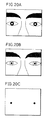
- Figs. 3A and 3B show an example of extraction of the feature points of the face provided by the experiment shown in Fig. 2.
- Blue marks 6 are applied on 4 portions of the face as shown in Fig. 3A.
- Reference light 9 is emitted from the illuminating apparatus 8 to an object 10 as shown in Fig. 2, the light reflected from the object is caught by a camera 10, blue component is extracted from the picked up image and is thresholded. The result is as shown in Fig. 3B.
- noise components 7 As well as the blue marks 6 are taken. The reason for this is as follows. Namely, when the object 10 is illuminated by the reference light 9, the light reflected therefrom can be divided into two components in a broad sense. One is the light 11 diffused and reflected at the surface of the object 10, which reflects the optical nature of the material reflecting the light.
- the component is effective in extracting features points such as parts of the face (mouth, eyelash, nose and so on) and the pupil, except the images reflected from cornea, out of those feature points which are necessary in eye tracking.
- the other is the component 12 regularly reflected from the surface of the object 10, which reflects the optical nature of the light source.
- the component 12 does not reflect the nature of the object 10, so that it tends to be the noise.
- the latter component is included much at smooth portions of the object 10. More specifically, when the object is a person, sweats on the face, glass frame, glasses, plastics and glasses around that person and so on are such smooth portions. In the example shown in Fig. 3B, the noise 7 corresponds to the sweat.
- Figs. 3A and 3B blue marks applied on the face are extracted.
- the foregoing is similarly applied when marks of different colors are used and the color components are to be extracted.
- the regularly reflected component 12 becomes noise in most case, when portions such as the eyes, nose, mouth and eyelashes are extracted from the natural image without using marks.
- a so-called active stereo vision is used as another method for detecting the shape of one's face without using marks
- moire topography and slit ray method are the representatives of such method, in which the object is illuminated by a prescribed controlled shape pattern, thresholded images (reflected pattern) are extracted from the reflected images and the three dimensional shape of the object is measured by using the feature of the reflected pattern corresponding to the extracted pattern.
- images formed by the regular reflection becomes noises, making it difficult to properly extract the reflected patterns, which are the features of the object.
- a pupil is an opening of an iris, which generally looks dark. Therefore, if the iris is dark brown, the pupil must be distinguished from the iris to be extracted.
- the pupil is a good feature point which is widely applied, since the size of the pupil is convenient, it is not very much influenced by the movement of eyelid, and it is convenient in the conversion to the eye fixation.
- the extraction of the pupil has been carried out in an eye camera and so on and a number of methods for extraction of pupil have been known.
- the distance between the illuminating apparatus and the image pickup apparatus is small and the apparatus moves corresponding to the movement of the head. Therefore, the illuminating apparatus have only to illuminate the eyeballs, and the image pickup apparatus have only to pick up the images of the eyeballs. Therefore, the influence of noise is small and the pupil can be extracted dependent only on the difference in intensity of the reflected light from the pupil and from the iris.
- eye tracking for the application to the interface must be carried out in the non-contact manner as described above. Therefore, not only the portions of eyeballs but a widerange permitting tracking of a movement at a distance should be taken.
- a method for extracting pupils out of images of one's face must be considered. In such case, it is very difficult to separate the pupils from the background noises by the above described methods.
- Fig. 4 shows another method for extracting the pupil, in which the light enters the pupil and the light reflected from the retina is picked up.
- a half mirror 23 is provided on an optical axis 22 of a taking lens 21 of a camera 20, and a conventional illuminating apparatus 24 is arranged such that the optical axis thereof coincides with the optical axis 22 by means of the half mirror 23.
- the usage of the half mirror 23 is essential.
- a visible wavelength cut off filter 25 is provided in front of the illuminating apparatus 24.
- the visible wavelength component of the light from the illuminating apparatus 24 is cut off by this filter 25, and the remaining part of the light meets the optical axis 22 of the lens 21 to illuminate the user 26.
- the light enters the pupil of the user 26, reflected at the retina, passes through the half mirror 23 to be picked up by the camera 20. Therefore, the pupil is taken brighter than the iris.
- the apparatus becomes large as it employs a half mirror 23.
- the range of image pickup is not only the portions near the eyeballs but wider including, for example, the face itself, the influence of the noise becomes large even in this method, making it difficult to extract pupils properly.
- the intensity of illumination may be increased.
- the intensity of illumination is increased, much power is consumed and much heat is generated.
- An image reflected from a cornea is the virtual image formed by the light regularly reflected on the convex surface of the cornea, and it moves in the same direction as the eyeballs in accordance with the movement of eye fixation. Therefore, it is one of the feature points necessary for eye tracking.
- a problem in extraction is separation from background noise.
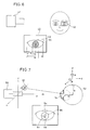
- Fig. 5 shows an example of an apparatus which takes images reflected from the cornea by a camera.
- a reference light source 31 illuminates eyes of a user 30
- images reflected from the cornea which are necessary for eye tracking are picked up by the camera 32.
- the display surface of the display 33 and from external illumination 34 such as a fluorescent lamp enter the eyes of the user 30, which is reflected from the cornea to provide virtual images. Therefore, there are various images reflected from the cornea in the eyeball, which are the noises making difficult the extraction of the images reflected from the cornea made by the light from the reference light source 31.
- the photographing time should be as small as possible in order to provide images without blurring.
- a camera with an electric shutter has come to be used recently.
- Such cameras having short photographing time requires intense illumination.
- a conventional illuminating apparatus is used for illuminating the user in the interface, the user is exposed to heat an intense light for a long period of time, which may affect the eyes or the body of the user.
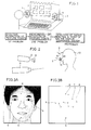
- Fig. 6 illustrates a method for detecting the iris and pupil in the white of the eye on a picked up image to detect eye fixation by using the same.
- the face of a person is picked up by a camera 41
- the portion 42 of the eye is extracted from the picked up image of the face
- the dark portion 43 and the white 44 in the eye are separated from each other.
- the length a of the white 44 and the length x from an edge of the white 44 to the center of the dark portion 43 are calculated.
- the direction of eye fixation is approximately in proportion to x/a. Since the process for extracting the white 44 and the dark portion 43 of the eye is difficult to carry out at a high speed, real time detection has not yet been realized.
- the degree of freedom is limited to the rotation movement of the eyeball unless the position and direction of the face are calculated by some method or another.
- the precision in detecting the rotation of the eyeball is not very high, since the size of the eye changes as the user changes his expression.
- the upward and downward movement of the eye is especially unique and complicated, as the dark portion 43 changes influenced by the movement of the eyelid.
- Fig. 7 illustrates a method for detecting the pupil and the images reflected from the cornea as feature points by one camera.
- the position of a reference light source 51 is assumed to be known in association with the coordinate system of the camera 50.
- the spatial position of the image 53 reflected from the cornea generated by the reference light from the reference light source 51 and the spatial position of the pupil 54 are determined independently based on the position of the center of rotation of the eyeball 52 and on the rotation angles ⁇ and ⁇ in the upward, downward, left and right directions of the eyeball.
- the center of rotation of the eyeball 52 and the rotation angle of the eyeball 52 are determined, and accordingly eye fixation can be determined.
- the positions of the image 53 reflected from the cornea and of the pupil 54 can be obtained from one projected image by providing a condition that the distance from the camera to the eyeball 52 is approximately constant.
- the eye fixation can be detected in association with the rotation angle a in the left and right directions and the rotation angle ⁇ in the upward and downward directions of the eyeball 52.
- the precision in detection becomes lower when the face moves in the direction of the z axis, from the above described condition.
- the gazing point In the examples shown in Figs. 6 and 7, it is difficult to detect the gazing point, since only one camera is employed. If any one of the above described methods is to be applied to the interface, it is necessary to know what point on the display the user is gazing. Therefore, the gazing point must be provided in the display coordinate system. In order to know the gazing point of the user on the display coordinate system, it is necessary to have the user gaze a predetermined point.
- An object of the present invention is to provide a method of detecting a gazing direction which can detect movement of eye fixation of a user in a non-contact manner without using any special device on the user, based on images from the object picked up by the image pickup apparatus.
- a still further object of the present invention is to provide a method of detecting a gazing direction which can detect eye fixation at high speed and with high precision while permitting free movement of the head of the user.
- a still further object of the present invention is to provide a method of detecting a gazing direction in which a gazing point can be detected on a display coordinate system which the user actually watches, and in which calibration can be carried out in a simple manner at the time of detection.
- the eye fixation is detected by two out of the three following feature sets: the position and direction of the face, the position of the pupil, and the image reflected from the cornea; so that the number of parameters for calibration to detect the gazing point of the user is small. Therefore, calibration can be carried out in a simple manner, the precision in detection is high and the burden on the user is small.
- the position of the center of the eyeball can be obtained in association with the measurement coordinate system. Only one constant vector in approximation, is needed as a parameter necessary in this process, so that the calibration can be carried out in a simple manner, and the direction of eye fixation can be detected independent from the movement of the head of the user in a non-contact manner by finding the center of the eyeball and the spatial position of the pupil. Since the number of parameters for calibration is small, the precision can be increased.
- the direction of eye fixation of two eyes can be separately provided, therefore, overlapping of the direction of the eyes can be detected and accordingly eye fixation can be detected not only on a plane but three dimensionally.
- the area of the pupil can be detected, so that the direction of eye fixation as well as the extension of the pupil can be detected simultaneously.
- the position and direction of the head can be detected based on three points on the face. If these three points are determined in advance, extraction of these three points can be facilitated by applying marks on these point, enabling detection of eye fixation at high speed.
- marks whose feature can be easily extracted are applied to at least three portions on a glass frame, and the head is turned into a model by the marks when the user wears the glass.
- the position and direction of the head can be detected in accordance with the positions of the marks. Therefore, in this embodiment, the head can be turned into a model only by providing marks on glasses, whereby the position of the head can be detected in a simple manner.
- the position of the head can be exactly detected so long as the pair of glasses is fit on the face, and therefore the eye fixation can be detected in a simple manner with high precision.
- Reference light may enter the eye, the position and direction of the head are detected from the taken image, the detected position of the head is moved and rotated, the position of the center of the eyeball which is independent from the rotation movement of the eyeball and is stable in position is detected, the position of the image reflected from cornea generated from the reference light is detected from the taken image, and the eye fixation is detected in accordance with the detected positions of the center of the eyeball and the image reflected from the cornea.
- the direction of eye fixation can be detected in non-contact manner independent from the movement of the head of the user.
- Fig. 8 shows the concept of the present invention and Fig. 9 shows types and characteristics of the feature points necessary for eye tracking.
- a face image is taken by a camera 60 and feature points reflecting the head and feature points of the eye are extracted from image signals, which are the outputs from the camera 60.
- the lateral angle of the eye, the medial angle of the eye, lip and so on can be detected by the difference in color as the feature points reflecting the head, as shown in Fig. 2.
- the feature points of the eye are the image reflected at the cornea, the dark portion of the eye and the pupil.
- the image reflected by the cornea is the virtual image formed by the light regularly reflected at the convex surface of the cornea, which moves in the same direction at the eyeball in proportion to the movement of the visual axis.
- the dark portion of the eye can be monitored by the difference in intensity of reflection between the iris and the retina.
- the movement of the dark portion can be extracted only by the room illumination with a reference light.
- the pupil can be detected by the difference in intensity of the light reflected from the retina at the iris and at this opening, and the pupil is not very much influenced by the movement of the eyelid.
- the position and direction of the head are detected from the extracted feature points reflecting the head, and the results are converted into the position of the the center of the eyeball. Meanwhile, the center of the pupil and the center of the dark portion are detected from the extracted feature points of the eye, and the direction of eye fixation is detected in response to the result and the position of the center of the eyeball provided by the conversion.
- the head is turned into a model.
- the turning into the model is carried out by using at least three feature points of the face at which the skin does not move very much.
- the position and direction of the head are detected based on the positions of the respective feature points on the face.
- At least three virtual feature points which are relatively static are taken out from at least four or more feature points on the face, and the position and the direction of the head are detected based on the positions of the virtual feature points.
- Marks whose feature can be easily extracted are applied at least three portions on a glass frame, the head is turned into the model using the marks when the user wears the glasses, and the position and direction of the head are detected based on the positions of the marks.
- Fig. 10 shows an image pickup apparatus that can be employed in the present invention
- Fig. 11 is a front view of a taking lens shown in Fig. 10
- Fig. 12 is a side view of the taking lens.
- an illuminating apparatus 61 and a lens 65 are arranged in front of a camera unit 60.
- the illuminating apparatus 61 comprises light emitting diodes 66 arranged around the lens, as shown in Fig. 11.
- a linear polarizer 63 is arranged in front of the light emitting diodes 66 and a visible wavelength cut-off filter 68 is arranged in front of the lens 65.
- the linear polarizer 63 polarizes the light emitted from the light emitting diodes 66, and the visible wavelength cut-off filter cuts off the visible light emitted from external illuminations such as a fluorescent lamp.
- An illuminating apparatus 62 is arranged at a position apart form the optical axis of the lens 65.
- the illuminating apparatus 62 comprises light emitting diodes 64 and a linear polarizer 67 provided in front of the same.
- the camera unit 60 comprises three prisms 607, 608 and 609.
- a wavelength separating plane 610 is formed between the prisms 607 and 608, and a half mirror 611 is arranged between the prisms 608 and 609.
- a polarizer 615 and a CCD image pickup image element 612 are arranged facing the light emitting surface of the prism 607.
- a CCD image pickup element 614 is arranged facing the light emitting surface of the prism 608, and a polarizer 616 and a CCD image pickup element 613 are arranged facing the light emitting surface of the prism 609.
- the polarizing surfaces of the polarizers 615 and 616 orthogonally intersect the linear polarizers 63 and 67 provided in front of the illuminating apparatuses 61 and 62.
- the outputs from the CCD image pickup elements 613 an 614 are applied to subtraction image operation means 617 in which the image reflected by the cornea is extracted.
- the outputs of the CCD image pickup elements 612 and 613 are applied to subtraction operating means 618 in which the pupil is extracted.
- Fig. 13 is a graph showing the optical characteristics of the optical parts employed in an image pick-up apparatus.
- Near infrared light which cannot be sensed by one's eyes is used for the light emitting diodes 64 and 66 employed in the illuminating apparatuses 61 and 62 shown in Fig. 10.
- the wavelength ⁇ 1 of the light emitting diode 64 is 850 nm while the wavelength ⁇ 2 of the light emitting diode 66 is 950 nm.
- the wavelength characteristics of the light emitting diodes 64 and 66 are as shown by 1 ⁇ and 2 ⁇ in Fig. 13.
- the characteristics of the visible light cut-off filter 68 provided in front of the lens 65 is represented by 4 ⁇ in Fig.
- the sensitivity of the CCDs 612, 613 and 614 is as shown by 3 ⁇ in Fig. 13.
- the half-band width of the wavelength is narrow in each of the light emitting diodes 64 and 66, so that the light emitted from the respective light emitting diodes 64 and 66 do not interfere with each other when the central wavelength of the two differ from each other by approximately more than 100 nm.
- the light having such wavelength cannot be sensed by the eyes of a man. If the light is sensed by the eyes of a man, the wavelength of the emitted light may be changed to be longer.
- the CCD image pickup elements 612, 613 and 614 formed of silicon have sufficient sensitivity in this range of wavelength as shown in Fig. 13.
- Fig. 14 is a perspective view showing an overview of an illuminating apparatus comprising light emitting diodes and a polarizer provided as a unit, as an example.
- light emitting diodes 72 are mounted on a base plate 71, and a frame 74 for mounting optical elements is attached to the base plate 71 spaced apart by a prescribed distance by means of a spacer 73.
- Optical elements 75 such as a polarizer, a visible wavelength cut off ⁇ infrared passing filter and so on are mounted on the frame 74.
- Holes for a camera lens are formed on the base plate 71 and on the optical element 75, and a cylinder 76 is provided for coupling these two holes.
- the optical elements 75 are covered by a frame 74 so as to increase mechanical strength to prevent skews or the like of the optical elements 75.
- This structure is especially important when the refractive index of the optical element 75 has anisotropy and the characteristics of the element changes dependent on the wavelength. More specifically, if the element has a skew as it is distorted or deflected, prescribed reference light may not be provided.
- the cylinder 76 prevents entrance of the reference light emitted from the light emitting diode 72 directly to the lens. Namely, the reference light and the reflected light are separated from each other by the cylinder 76.
- the light emitted from the light emitting diodes 64 and 66 of the illuminating apparatuses 61 and 62 is polarized by the polarizers 67 and 63, respectively, to illuminate a person.
- Light reflected therefrom enters the prism 607 through the visible light cut-off filter 68 and the lens 65.
- the light having the wavelength ⁇ 2 (950 nm) is separated by the wavelength separating film 610 to enter the CCD image pickup element 612 through the polarizer 615 to form an image.
- an image with the regularly reflected component cut off that is, an image including the diffused reflection component is formed on the photosensitive surface of the CCD image pickup element 612 when the direction of polarization of the polarizer 615 is shifted by 90° to be in the vertical direction. Since the regular reflection occurs on smooth surfaces of the object, the optical characteristics of the light source are very well kept in the regularly reflected components.
- the diffused reflected component is modified by the absorbing ⁇ reflecting characteristics of the object.
- the diffused reflected image should preferably be used in view of noise reduction and improvement of S/N.
- the reflected light having the wavelength ⁇ 1 passes through the visible wavelength cut-off filter 68, the lens 65 and the prism 607 to be divided by a half mirror 611 provided at the interface between the prisms 608 and 609. Part of the divided light enters CCD image pickup element 613 through the polarizer 616 to form an image, at the other part of the divided light directly enters the CCD image pickup element 614 to form an image.
- an image including the regularly reflected component and the diffused reflected components is included in the outputs from the CCD image pickup element 614, while an image including the diffused reflected component only is included in the outputs from the CCD image pickup element 613. Since the intensity of the light passed through the polarizers 615 and 616 becomes 1/2, the ratio of division at the half mirror 611 is set at 1:2, so that the intensities of the images from the CCD image pickup elements 613 and 614 are approximately the same.
- Fig. 15A shows a diffused reflected image picked up by an image pick up apparatus
- Fig. 15B shows the effect of extracting feature points.
- Fig. 15A shows an example of extraction of the diffused reflected component out of the reflected light caught by the camera in accordance with the above described method.
- Fig. 15B shows images provided by extracting face color components out of the pixels of Fig. 15A and by thresholding the same.
- the extraction of the images reflected from the cornea will be described in the following.
- the images reflected from the cornea are the virtual images formed by the light of the reference light source regularly reflected on the surface of the cornea. Therefore, in this case, the regularly reflected images are the desired signals.
- the extraction of the images reflected from the cornea is realized by extracting the difference between the images on the CCD image pickup elements 613 and 614 shown in Fig. 10 by the subtraction operating means 617.
- a problem in extracting the images reflected by the cornea in the prior art was that the light from external surfaces or from the display is reflected from the cornea to form images which overlap with the images derived from the reference light source.
- the light from the light emitting diode 64 is polarized, so that the images reflected from the cornea which is formed by reflection of the light from the light emitting diode 64 are cut off by the polarizer 614 orthogonally intersecting therewith, leaving the diffused reflected images. Therefore, the image reflected by the cornea can be extracted from the background by the subtraction operating means 617 as described above.
- the external illumination is not polarized in general, similar images are picked up by the CCD image pickup elements 613 and 614, and there is no difference between the images taken by these two elements. Therefore, the different image provided by the subtraction operating means 617 include less noise, whereby extraction of the image reflected by the cornea with high S/N can be realized.
- Fig. 16A to 16C show example of extraction of the image reflected from the cornea. Examples shown in Figs. 16A to 16C are the results of experiment for extracting the image reflected from the cornea using the same image pickup system as shown in Fig. 10, in order to confirm the above described concept.
- Fig. 16A shows an image provided form the CCD image pickup element 614, including the regularly reflected component and the diffused reflected component.
- Fig. 16B show images provided from the CCD image pickup element 613 including only the diffused reflected component.
- the subtracted image outputted from the subtraction operating means 617 corresponds to Fig. 16C, in which the images reflected from the cornea is clearly extracted from the background.
- the first illuminating apparatus 61 comprises light emitting diodes 66, which are arranged around the optical axis of the lens 65 as shown in Fig. 11.
- the pupil is taken brighter than the background.
- the second illuminating apparatus 62 is arranged apart from the optical axis of the lens 65.
- the reflected image derived form the illumination of the illuminating apparatus 62 that is, the image provided from CCD image pickup element 613 or 614 the pupil is picked up dark. Therefore, by the subtracting operation between the image provided from CCD images pickup element 612 and the image provided from the CCD image pickup element 613 or by the subtracting operation between the image provided from the CCD image pickup element 12 and the image provided from the CCD image pickup element 14, the pupil is further emphasized against the background, whereby the extraction thereof is facilitated. Since the conditions of mounting the second illuminating apparatus 62 is not very strict as described above, it may be substituted by an external illumination such as the fluorescent lamp. However, in that case, the reflected light of the illumination must reach the CCD pickup element 613 or 614, therefore, the external illumination have to comprise near infrared component, or the lens visible wavelength cutting off filter 68 have to be removed.
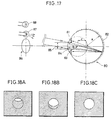
- Figs. 17, 18 and 19 illustrate arrangement of light sources for taking the pupil bright.
- the eyeball 80 may be regarded as a model of a composite sphere in which transparent spheres having different radii are overlapped with each other with the centers thereof spaced apart from each other. Let us consider a case in which the eyeball 80 which is on the optical axis of the taking lens 86 is illuminated and the light reflected therefrom is to be caught. An opening portion of the iris 81 of the eyeball 80 is the pupil 85. The light emitted from a light source 87 enters the eyeball through the pupil 85, reflected at the cornea, passes through the pupil 85 and reaches a diffusing reflecting surface 82 corresponding to the retina.
- Part of the light is absorbed by the retinal cells.
- the remainder of the light is diffused and reflected here.
- a part of the reflected light which can pass through the pupil 85 again returns approximately to the direction of the light source. Therefore, if the taking lens 86 is arranged in this direction to catch the reflected light, the portion corresponding to the pupil 85 will be bright in the picked up image.
- the taking lens 86 is placed away from the light source 87, it becomes difficult to sufficiently catch the reflected light, and the area which is bright at the portion of the pupil 85 will have a unique shape.
- the light source 87 is placed near the optical axis of the taking lens 86, the bright area in the pupil 85 become larger as shown in Fig. 18B.
- the light source is away from the taking lens 86, as represented by 88, the bright area is considerably biased, as shown in Fig. 18A.
- the center of the pupil 85 cannot be properly provided even if the thresholding operation is carried out to find the center, as the brightness of the pupil image is not uniform. Therefore, error may possibly occur in eye tracking. In view of the precision in eye tracking, it is particularly desired that the pupil 85 is picked up with uniform brightness.
- the light sources 87 are arranged near and around the optical axis of the taking lens 86.
- Fig. 18C schematically shows the pupil image picked up by using the illuminating apparatus 61 shown in Fig. 11.
- the light emitting diodes 66 shown in Fig. 11 serves to pickup a specified portion of the pupil 85 bright as shown in Fig. 18A.
- the pupil image picked up by the sum of the functions of the light emitting diodes 66 arranged around the optical axis is uniformly bright.
- the structure having the light sources 87 arranged near the lens optical axis is realized only when a compact and effective light sources such as light emitting diodes 66 are used.
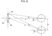
- the parameter 1 ⁇ is defined by the environmental condition in which the eye tracking method is employed.
- the position d of the eyeball is 50 cm to 200 cm
- the position g of the eyeball is ⁇ 30 cm
- the rotation angle ⁇ is ⁇ 20 o .
- the condition of arrangement of the light sources for taking bright at least a portion of the pupil as shown in Figs. 18A and 18B is found through experiments.
- the condition is defined by an angle ⁇ defined by a segment connecting respective light sources to the object to be picked up and the segment connecting the center of the lens to the eyeball, with the value of the angle ⁇ being ⁇ th1 (5°) or less.
- the pupil has no portion taken bright. Namely, whether the pupil is picked up bright or dark is determined by the angle ⁇ , with the boundary value being 5°.
- the values of ⁇ th1 and ⁇ th2 are set dependent on the conditions of the environment. Therefore, in the illuminating apparatus 61 for taking bright the pupil image, the respective light sources around the lens optical axis should be set with the angle no more than 8thl. As for the number of the light sources, the more the better. Preferably, three or more light sources may be used.
- the portion of the pupil can be emphasized against the background.
- Fig. 20A to 20C show examples of the images picked up by the apparatus shown in Fig. 10.
- Fig. 20A is an image picked up by the CCD image pickup element 612
- Fig. 20B is the image picked up by the CCD image pickup image element 614.
- the portion of the pupil can be extracted with high S/N, as shown in Fig. 20C.
- the pupil is picked up bright by taking the light reflected at the retina of the eyeball out of the pupil.
- This technique can be utilized for extracting feature points. More specifically, in a method of detecting position and direction of one's face by applying marks on the face and extracting these marks, transparent balls can be used as the marks.
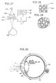
- Fig. 21 shows an example of the mark applied to an apparatus.
- a diffusing reflecting layer 91 is formed by applying a coating such as a white paint on a glass ball 90.
- a coating such as a black paint is applied further thereon to provide a light absorbing layer 92.
- the light enters the glass ball 90 through an opening portion, reflected at the curvature of the opening portion and reaches the diffusing surface.
- the incident light is condensed as shown in Fig. 21, since the curvature of the opening portion serves as a lens.
- the light reflected on the diffusing surface is reflected approximately in the direction of the incident light, as the curvature serves as the lens when the light passes through the opening portion.
- the opening portion is taken brighter than that periphery in the image picked up by the CCD image pickup element 612. Since the reflected light derived from the light of the illuminating apparatus 62 provided apart form the taking lens 65 is not taken by the camera 60, as in the case of the eyeball, the opening portion becomes dark in the images picked up by the CCD image pickup elements 613 and 614. Therefore, by the subtracting operation between the two different images, the opening portion can be extracted as the feature point. In this manner, the opening portion of the glass ball 90 can be extracted in the similar manner as extracting the pupil.
- a glass ball 90 having the diameter of 3 to 5 mm may be used, which is preferably attached to a portion of the face on which the skin does not move much, or the glass ball may be embedded on the frame of glasses.
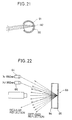
- Fig. 22 is a cross sectional view showing another example of the mark.
- the mark 93 is a circle having the diameter of about 2 to 5 mm, which is formed by processing glass.
- a film 94 which transmits light having the wavelength longer than 900 nm and reflects the light having the wavelength no longer than 900 nm is formed on the surface, and the rear surface is a diffusing reflecting surface 95. Therefore, light having the wavelength longer than 900 nm is diffused and reflected by the rear surface to be caught by the camera.
- the light having the wavelength no longer than 900 nm is reflected on the surface of the mark 93. However, if the direction of reflection is different from the direction of the taking lens, the light is not picked up.
- this light since this light is regularly reflected, it can be cut off by using a polarizer.
- the marked portion becomes bright.
- the mark becomes dark. Therefore, by the subtraction between these images, the marked portion as well as the pupil can be extracted.
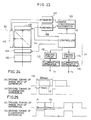
- Fig. 23 shows an electric shutter type image pickup apparatus.
- an electric shutter type camera 101 comprises a lens 102, an electric shutter 103, an optical apparatus 104 for separating images corresponding to wavelength, an image pickup element 105 for picking up images having the wavelength ⁇ 1 and an image pickup element 106 for picking up images having the wavelength ⁇ 2 .
- the outputs from the image pickup element 105 are applied to a memory 107 while the image pickup outputs from the image pickup element 106 are applied to a memory 108.
- the memories 107 and 108 respectively store image pick up outputs.
- An image processing apparatus 109 processes image outputs stored in the memories 107 and 108, respectively, and outputs, for example, the difference therebetween.
- the electric shutter 103 and the image pickup elements 105 and 106 are controlled by a controller 110, which is formed of, for example, a microcomputer.
- An illuminating apparatus 111 comprises an illuminating apparatus 113 emitting light having the wavelength ⁇ 1 and an illuminating apparatus 115 emitting the light having the wavelength ⁇ 2 , which are driven by driving circuits 112 and 114, respectively, under the control of the controller 110.
- Figs. 24 and 25 show driving timings of the image pickup apparatus and the illuminating apparatus shown in Fig. 23.
- the electric shutter type camera 101 shown in Fig. 23 is capable of picking up a moving object with no or little blurring.
- the concept of the camera is as follows.
- the electric shutter 103 is opened for a short period of time to expose the image pickup elements 105 and 106.
- Image signals are temporarily stored in the image pickup element 105 and 106 during a short period of time 116, for example, 1 msec, as shown in Fig. 24(b). Thereafter, at the timing 117 shown in Fig. 24(a), the image signals which are the outputs from the image pickup elements 105 and 106 are transferred to the memories 107 and 108.
- the electric shutter 103 is again opened, the image pickup elements 105 and 106 are exposed, and the operation is repeated.
- image pickup element having high sensitivity must be used as the image pickup elements 105 and 106.
- the light must be more intense as the shutter speed becomes faster.
- the light emitting diode can be turned on/off at high speed, larger current can flow therethrough under intermittent driving condition compared with the continuous driving, and therefore the light provided by the diode is more intense. Therefore, at the time of exposure of the image pickup element 105 and 106, sufficient light can be emitted. In this manner, the illuminating apparatus 111 employing light emitting diodes meet the demand of intense illumination at a short time period, which is desired for the electric shutter type camera 101.
- the exposure time of one image plane of the image pickup elements 105 and 106 is in the range of about 33 msec to 0.5 msec.
- the time of illumination is no more than 1/1000, compared with the continuous illumination.
- a light emitting diode which conducts only about 50 mA when it is continuously driven, conducts several A current by intermittent driving. Therefore, illumination required for exposure can be ensured.
- external illumination should be preferably cut off as they cause noises.
- An effect of the reduction of the exposure time is that the intensity of external illumination becomes relatively low in comparison with the intensity of the illuminating apparatus. Therefore, the reflection component derived from external illumination becomes relatively small, and accordingly the noise component becomes smaller and improve S/N ratio.
- illumination of the necessary intensity is provided only when it is needed, power consumption can be reduced and less heat is generated.
- Fig. 25 shows timings for driving the illuminating apparatus.
- image pickup is carried out time divisionally, with two images considered as a set.
- the time required for picking up one image plane is 33 msec, for example, which is represented by A1 and A2.
- the illuminating apparatus is on.
- the illuminating apparatus is off.
- the images picked up at the times A1 and A2 are both illuminated by the external illumination.
- the condition of the external illumination is the same at the times of A1 and A2, the image with the illuminating apparatus being on can be extracted by subtracting the image at the time A2 from the image picked at the time A1.
- An image processing apparatus in which feature points of an object to be picked up are extracted on real time that is, 30 images/sec will be described in the following as an application.
- the method for image pickup which facilitates extraction of feature points must be selected, such as applying marks on the face or the body or providing reference light.
- these selection is not sufficient for the real time detection.
- the high speed operation of the image processing apparatus is essential.
- the above described feature points can be easily extracted by the subtracting operation between two images.
- Fig. 26A is a schematic block diagram showing a whole structure of an image processing apparatus in which feature points are detected on real time by employing the image pickup apparatus.
- Fig. 26B is a specific block diagram of the image processing apparatus shown in Fig. 26A.
- FIG. 26A R, G and B image signals picked up by near infrared cameras 121 and 122 are respectively applied to image processing apparatuses 123 and 124, processed therein and applied to a host computer 125.
- the image processing apparatuses 123 and 124 are structured as shown in Fig. 26B.
- the image processing apparatus 123 is basically consisted of a module 130 in which a timing signal for pipe line processing is formed from inputted signals.
- Other input modules 131 and 132 and various pipe line processor modules 153, 154, 155 and 156 connected to the module 130 operate in parallel.
- the near infrared camera 121 comprises CCD image pickup elements 612, 613 and 614, the image signals from which are separately applied to the modules 130, 131 and 132, respectively.
- the modules 130, 131 and 132 turns image signals into pixel data by A/D conversion in synchronization with the output signals from the CCD image pickup elements 612, 613 and 614, respectively, and the pixel data are successively applied to the pipe line processor modules 133, 134, 135 and 136, through video busses.
- Each of the pipe line processor modules 133, 134, 135 and 136 has a plurality of inputs. For example, in a subtracting operation between two images, the pipe line processor module 133 carries out subtraction on B-R and thresholding operation. The pipe line processor 134 carries out subtraction B-G and the thresholding process.
- the pipe line processor 135 takes the image signals processed in the pipe line processors 133 and 134, and the pipe line processor 136 calculates the center of gravity of the extracted feature points.
- the calculated barycentric coordinates are transferred through a repeater 138 to the host computer 125 to detect the eye fixation.
- the A/D converted pixel data are processed through a plurality of pipe line processor modules 133 to 136 while one image is taken.
- the time required for processing one image is the time 33 msec in which the final pixel is taken, plus the delay time in the pipe line processing.
- the input modules 130, 131 and 132 can start taking of the next image as soon as they transfer the final pixel to the processor. Therefore, in an image processing realized by simple four rules (subtracting process between images), the real time processing can be realized at the rate of 33/sec with the delay time of 33 msec + ⁇ .
- Figs. 27, 28 and 29 show an application to the active stereo vision measurement.
- reference light emitted from an illuminating apparatus 141 employing light emitting diodes as light sources illuminates an object 145 through a lens system 142, a shape pattern 143 and a polarizer 144.
- the object is, for example, the face of a person.
- the shape pattern 143 is as shown in Fig. 28, for example, and the reference light from the light source 141 projects the pattern 146 of the shape pattern 143 onto the object 145 by the lens system 142.
- the light reflected from the object 145 passes through the taking lens 151 and the polarizer 152 so as to form an image on the image pickup element 153.
- the polarizing surface of the polarizer 152 is rotated by 90 o about the polarizing surface of the polarizer 144.
- Fig. 29 shows an image of the pattern projected on the object 145 picked up by the image pickup element 153.
- the object 145 has smooth parts.
- the reference light is regularly reflected on these portions, so that the regularly reflected images disturbing the projected pattern generally appear in the projected image of Fig. 29 in the prior art without polarization.
- the noise components derived from the regularly reflected images can be reduced, whereby the shape pattern image reflecting the feature information of the shape of the object can be effectively extracted, as shown in Fig. 28.
- the eye tracking apparatus will be described in the following and the eye fixation will be described prior to the detailed description of the apparatus.
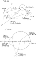
- Fig. 30 schematically shows the structure of an eyeball.
- a transparent film covering the front surface of the eye is the cornea 161.
- the converging of the light to the retina 162 is mostly carried out by the cornea 161.
- Fine adjustment (adjusting function) for focusing an object is carried out by changing the thickness of a lens 163.
- a portion called a fovea 164 which has the highest resolution on the retina 162 exists on a point of a line passing through the cornea 161 and the optical axis of the lens 163.
- the eye moves such that the image of the object is formed on the fovea 164. Therefore, we may consider that the visual axis is approximately on the image forming optical axis.
- the center of the pupil 165 and the rotation center of the eyeball are also in the proximity of the optical axis. Therefore, eye tracking is basically possible by calculating the position of the center of the pupil and the center of the eyeball.
- the algorithm of eye tracking will be described with the visual axis regarded as the line coupling the center of the eyeball and the center of the pupil.
- the correction for the case where the direction of the visual axis is different from the line in strict sense will be described later.
- the stereo vision measurement in which a world coordinate system is provided on a display screen which the user watches, and the positions of the above described feature points necessary for eye tracking are measured on this coordinate system will be described in the following.
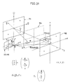
- Fig. 31 illustrates the stereo vision measurement.
- (X and, Y and, Z and) represents the world coordinate system 161, which overlaps with the display screen.
- a mirror 164 is inserted in parallel to the X and Y and plane at a prescribed position in the direction of the Z and axis of the world coordinate system 161 only when the stereo measurement system is to be calibrated.
- (X, Y, Z) represents the coordinate system which is a projection of the world coordinate system 161 with the X andY and plane thereof projected by the mirror 164. It is called an object coordinate system 162.
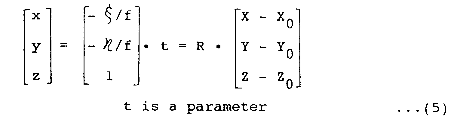
- (x, y, z) represents a coordinate system 163 of the camera with the origin o being the principal point of the lens.
- An image pickup surface 165 is positioned spaced apart by the focal length f from the principal point o.
- the object to be picked up by the camera is the object coordinate system 162, which is the mirror image of the world coordinate system 161. Namely, the object coordinate system 162 faces the display, and the user may be seated near the position thereof in the environment of the interface.
- the ultimate object of the present invention is to utilize the movement of the eye in the field of interface, and therefore eye tracking on the display coordinate system is necessary. Accordingly, the feature points of the person must be exactly found on the display coordinate system.
- the positions of the feature points taken on the camera coordinate system 163 is to be converted onto a coordinate system different from the camera coordinate system 163, calibration is necessary.
- a point whose position is known beforehand is prepared on a coordinate system to which the position is to be converted, the point is picked up by the camera, and the parameters for conversion are calculated. Since the measurement should preferably be carried out on the display coordinate system in accordance with the object of the present invention, the calibration is realized basically by displaying a point whose position is definite on the display and by picking up the point by the camera. However, in that case, the camera naturally faces the display and it can not pick up the user facing the display.
- a mirror 164 is provided in front of the world coordinate system 161 at the time of calibration as shown in Fig. 31 and the virtual image on the mirror is used as the data for calibration.
- the virtual image is picked up by the camera, and the spatial position of the virtual image is precisely found on the world coordinate system 161.
- the point P on the world coordinate system 161 is reflected by the mirror 161 and appears as the point P on the object coordinate system 162, as shown in Fig. 31.
- the light is reflected by the mirror 164 as represented by the arrow 1 ⁇ in Fig. 31. Viewed from camera coordinate system 163, the light is measured as coming from the coordinate system 162, as represented by the arrow 2 ⁇ .
- the mirror 164 is arranged such that the position and direction thereof are definite in association with the world coordinate system 161. By doing so, the conversion from the world coordinate system 161 to the object coordinate system 162 is facilitated. For example, when the mirror 164 is arranged orthogonally intersecting the Z axis of the world coordinate system 161, the spatial position coordinate on the object coordinate system 162 can be converted into the world coordinate system 161 only by inverting the sign in the direction of the Z axis. If the conversion between the world coordinate system 161 and the object coordinate system 162 is easy, the conversion between the camera coordinate system 163 and the world coordinate system 161, that is, the display coordinate system is enabled by establishing a method of conversion between the camera coordinate system 163 and the object coordinate system 162.
- the position of the camera (X 0 , Y 0 , Z 0 ), the rotation angle ( ⁇ , ⁇ , ⁇ ) defining the direction of the optical axis of the camera and the inclination of the camera, and the focal length f are determined.
- N N ⁇ 4.
- the most exact value is determined by the method of least squares as will be shown in the solution in the following, and therefore the value N should be relatively large.
- the solution will be described in the following. Due to the errors in the measurement, the left side of the equation (9) will be not 0 but ⁇ i and ⁇ i . Therefore, the solution can be calculated by miniaturizing the sum of squares of errors ( ⁇ i 2 + ⁇ i 2 ).
- the object coordinate system 162 can be easily converted into the world coordinate system 161, all the parameters for measurement can be calculated for the world coordinate system 161.
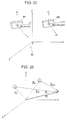
- Fig. 32 and 33 illustrate a method for calculating three dimensional position of an image picked up by two cameras arranged arbitrarily in the world coordinate system.
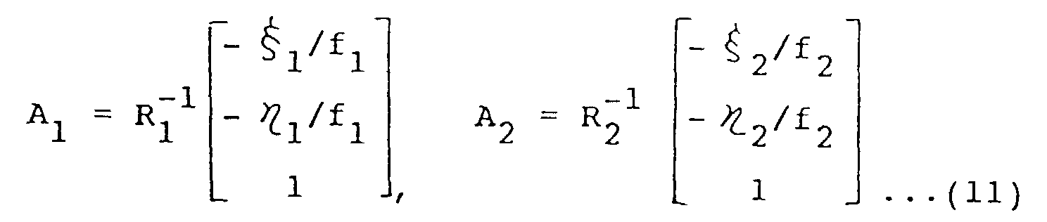
- a point P(X and, Y and, Z and) in the world coordinate system 161 is picked up by the two cameras 165 and 166
- the coordinates of the images picked up by these two cameras are respectively represented as ( ⁇ 1 , ⁇ 1 ) and ( ⁇ 2 , ⁇ 2 ).
- the values t 1 and t 2 can be calculated by the equations (10). However, since the value P 1 is not equal to the value P 2 due to the errors in measurement, a closest point is calculated. In this manner, a spatial position of an arbitrary point in the world coordinate system 161 can be measured by using two images.
- the direction of the visual axis can be calculated as a line coupling the coordinate of the center of the eyeball and the coordinate of the pupil. Since the pupil can be directly picked up by the camera, the world coordinate system thereof can be provided in accordance with the algorithm of the stereo vision measurement described above. Although the center of the eyeball cannot be directly measured, it is assumed that the position of the center of the eyeball is fixed in a head coordinate system consisted of three feature points on the face. Therefore, the coordinate of the center of the eyeball given in the head coordinate system is converted into the world coordinate system 161.
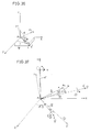
- Fig. 34 shows an embodiment of eye tracking.
- the world coordinate system 161 may be regarded as the display coordinate system in Fig. 34.
- the spatial positions of all the feature points which can be directly picked up by the camera can be found in the world coordinate system 161.
- the origin is at the center P G of a triangle (P 1 , P 2 , P 3 ), and the direction a segment coupling P 1 and P 2 is regarded as the x axis, a direction orthogonally intersecting the x axis is regarded as the y axis, and the normal direction of the triangle is regarded as the z axis.
- the reference character e represents a position vector of the center of the eyeball 171 in the head coordinate system. Although it is unknown at present, this is a constant vector.
- the position from the center P G can be measured by some method or another.
- the vector can be calculated by calibration, as will be described later. Therefore, in the following, it is assumed that the vector is given as an input data.
- the output data is the world coordinate value C(X c , Y c , Z c ) of the center of the eyeball.
- the direction of the eye fixation can be calculated as D(X D , Y D , X D ) - C(X c , Y c , Z c ) in Fig. 34.
- the problem in the foregoing is the conversion of the head coordinate system (x, y, z) into the world coordinate system (X and, Y and, Z and).
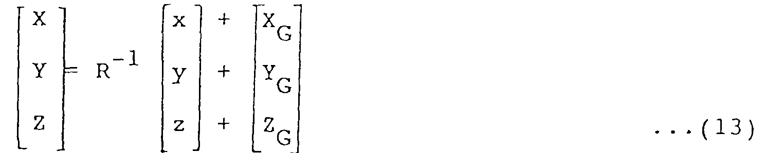
- Fig. 35 illustrates the conversion of the coordinate including movement of the origin and the rotation of the axis of the coordinate.
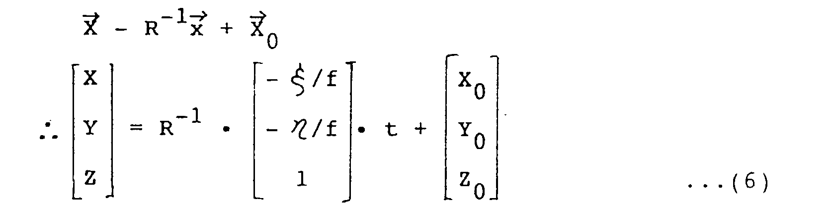
- the conversion of the coordinate including the movement of the origin and the rotation of the axis of the coordinate is realized in accordance with the following equation (12) in general.
- the inverse transformation is represented by the following equation (13).
- the value R -1 is represented by the following equation (14) assuming that the world coordinate system is rotated by ⁇ around the Y axis, then rotated by a around the X axis and then by ⁇ in the direction of the Z axis so that it corresponds to the head coordinate system.
- Fig. 36 shows the movement of the origin of the world coordinate system which is the feature point P 1 of the face shown in Fig. 34.
- the z direction of the head coordinate system assumed to be equal to the normal vector N of an image pick-up apparatus the triangle formed by the three points on the face.
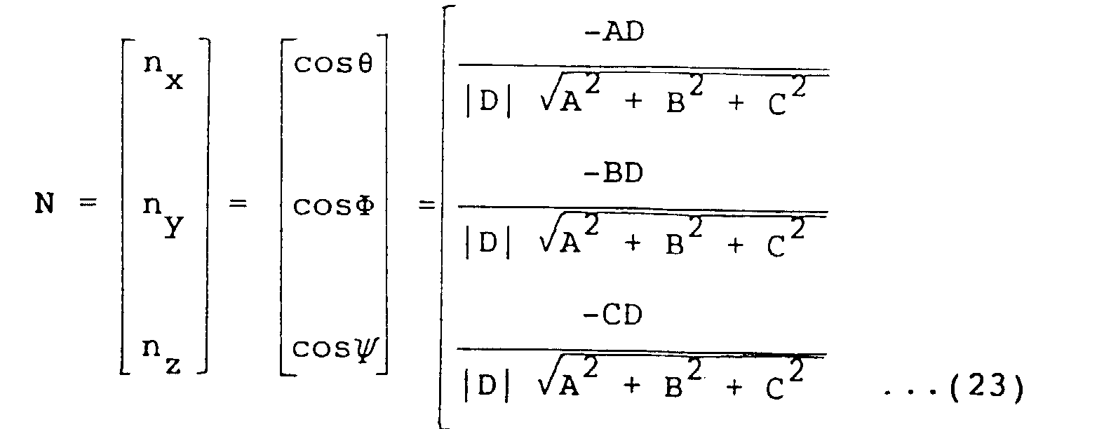
- the direction cosine of the normal vector of the triangle in the world coordinate system can be represented as the following equations (15).
- the direction cosine (n x , n y , n z ) of the normal vector of the triangle can be calculated in the similar manner based on the condition that the world coordinate system is rotated by ⁇ around the Y axis, then rotated by ⁇ around the X axis so that the Z axis corresponds to the Z axis of the head coordinate system.
- the reference numeral (1) represents the rotation of the world coordinate system around the Y axis by ⁇ .
- (X, Y, Z) is turned to (X', Y', Z') represented by the dotted lines.
- the reference numeral (2) indicates the rotation of the world coordinate system around X' by ⁇ .
- the Z' axis coincides with the z axis. Therefore, from Fig.
- the world coordinate system is rotated by ⁇ around z axis (that is, N) of the head coordinate as shown by the reference numeral (3), so that X' axis overlaps with the x axis of the head coordinate system.
- both the X and Y axes are in parallel to the head coordinate system.
- the value R -1 can be calculated by substituting the values of the above equations (26) for the equation (20). Therefore, in accordance with the equation (21), the point in the head coordinate system can be converted into the world coordinate system. Therefore, the position of the center of the eyeball can be calculated in the world coordinate system.
- the character t represent a parameter indicating the distance to the index, which can be calculated by various methods. If the display provided on the world coordinate system is a plane (for example, the YZ plane is the display surface in Fig. 34), the origin and the direction of the visual axis vector (D - C) are calculated, and therefore, the point at which the vector encounters the display can be uniquely calculated on the display coordinate.
- the display provided on the world coordinate system is a plane (for example, the YZ plane is the display surface in Fig. 34)
- the origin and the direction of the visual axis vector (D - C) are calculated, and therefore, the point at which the vector encounters the display can be uniquely calculated on the display coordinate.
- a gazing point not on a plane can be also detected. Namely, a spatial gazing point can be extracted.
- Al and A2 the vectors to arbitrary points on the left and right visual axes as Al and A2
- the following equation (28) is provided in accordance with the equation (27).
- the estimation of the coordinate of the center of the eyeball will be described in the following.
- the position of the center of the eyeball is assumed to be fixed in the head coordinate system and therefore it is regarded as an input data in the foregoing.
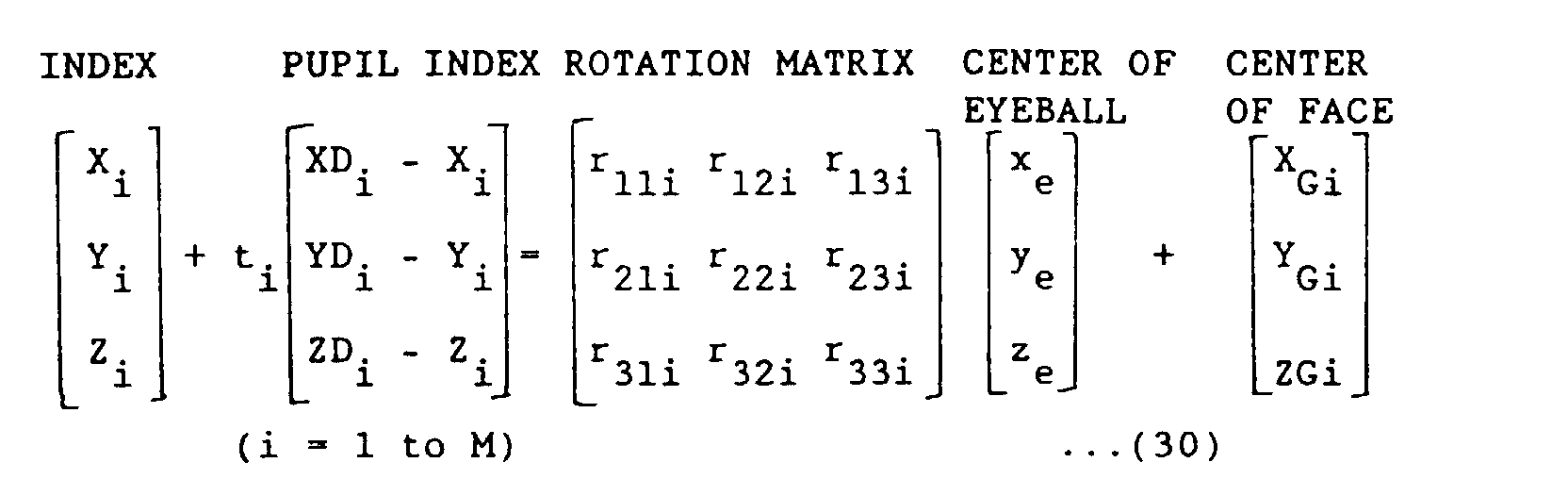
- a subject is made to successively look at M points L i (X i , Y i , Z i ) the coordinates of which are known in the world coordinate system.
- the world coordinate D i (X Di , Y Di , Z Di ) of the pupil at that time and the world coordinates P 1i (X 1i , Y 1i , Z 1i ), P 2i (X 2i , Y 2i , Z 2i ) and P 3i (X 3i , Y 3i , Z 3i ) of the three feature points on the face constituting the head coordinates are measured.
- the closest value of the coordinate e(x e , y e , x e ) of the center of the eyeball in the head coordinate system is estimated using the method of least squares.
- the vector of the center of the eyeball in the head coordinate system is represented as e
- the vectors of the center of the pupil, the center of the three feature points on the face and the vector of the point L i when the subject looks at the point L i are respectively represented as D i , P Gi , L i in the world coordinate system.
- the vector e is represented in the world coordinate system
- the following equation (29) is applied as is apparent from Fig. 38, since it is R i -1 • e.
- t i is a parameter (t i > 1)
- r 11i , r 12i ... r 33i are elements of the rotation matrix R i -1 , which are provided by substituting the equation (26) for the equation (20).
- t i By eliminating the term t i from the equation (28) and by arranging the expression for x e , y e and z e , the following equations (31) are provided.
- the parameter which must be calculated by calibration is only the central position of the eyeball on the head coordinate. Therefore, the number of indexes presented in front of the subject for calibration may be small. Since the calibration can be carried out in a simple manner, the number of errors caused by the difference of the subjects can be reduced, and high precision can be realized.
- the visual axis is regarded as a line coupling the pupil and the center of the eyeball in the foregoing, it does not always coincide with each other in the strict sense.
- Fig. 39 shows a case in which the center of the eyeball does not exist on a line coupling the pupil and the fovea.
- the position of the center of the eyeball is assumed and the vector from the assumed point to the fovea may be calculated by some means or another or the vector may be calculated as a constant vector during calibration.
- it is effective to calculate the point of the center of the eyeball which is independent from the rotation of the eyeball and does not move much in detecting eye fixation.
- the above described problem can be treated in a further improvement.
- calibration in consideration of the influence of the glass lenses must be carried out. In that case also, the calibration can be carried out by the improvement of this invention.
- the method using the pupil and the images reflected from the cornea employ only the feature points in the eye. Assuming that the positions of the light sources are known and the structure of the eyeball is constant, the images reflected from the cornea is determined uniquely dependent on the position of the center of eyeball and the position of the pupil (corresponding to the rotation of the eyeball). Therefore, the position of the center of the eyeball can be calculated from the images reflected from the cornea and on the position of the pupil by using the parameter of the eyeball structure.
- the visual axis can be calculated from the center of the eyeball and the position of the pupil.
- the parameters of the eyeball structure comprise the radius of the eyeball, the radius of curvature of the cornea, and the distance between the center of the eyeball and the center of the curvature of the cornea. These parameters may be measured in advance or they may be calibrated during use with the user looking at a specified portion on the display.
- Fig. 40 shows an example of a model of the head employing glasses having marks. If it is difficult to apply marks on the face, marks 172 may be applied on three portions on the frame of the optical glasses as shown in Fig. 40. By wearing these glasses 171, the head can be turned into a model by the marks 172. How to extract these marks 172 will be described later together with the extraction of the pupils. Although three points on the face are used for modeling in the example shown in Fig. 40, four or more points may be used.
- Fig. 41 shows a case in which four points are used for modeling.
- the center of the eyeball is calculated by a second triangle 174 instead of a first triangle 173 in case where the first triangle 173 cannot be found as the feature points could not be well extracted. Since the head of a person moves variously, the respective feature points are not always caught by the camera actually. Therefore, in the actual application, a plurality of triangles may be prepared to be switched as needed, in order to continuously tracking the eyes.
- Figs. 42A and 42B show examples of calculation of a static virtual feature point out of two feature points on the face.
- the positions of the medial angle of the eye and the lateral angle of the eye change as the person narrows his eyes. However, when the person narrows his both eyes (as one usually does), the position of the center between the two feature points on the lateral angle of the eye hardly changes. The same can be applied on the corners of the nose, eyelashes and so on. Since the skin moves more than the muscles on the face, when a portion extends, another portion shrinks without fail. Therefore, by preparing the expressions and the corresponding movements on the skin as data base, relatively static feature points can be virtually provided. By using such virtual feature points, the precision in eye tracking can be further improved. It is desired to track the movement of the eye as well as the expressions in the future
- Fig. 43 illustrates another embodiment of eye tracking.
- an illuminating apparatus 181 is provided and a reference light 182 is emitted from the illuminating apparatus 181.
- the cornea can be regarded as a convex lens, virtual image is formed in the cornea when the reference light 182 is approximately parallel, so that it seems as if the light source is on this point. This is called the image 183 reflected from the cornea.
- the position E of the image 183 reflected from the cornea is uniquely calculated dependent on the position of the center 184 of the eyeball, a point (for example the center 185 of the curvature of the cornea) on the optical axis of the cornea and the radius of curvature ge of the cornea.
- the position of the center of the eyeball is A + B here, which can be calculated as described above. Therefore, when the position of the center 185 of the curvature of the cornea is calculated, the eye fixation can be detected.
- the position of the center 185 of the curvature of the cornea can be geometrically calculated by using the position of the center 184 of the eyeball and the position E of the image reflected from the cornea. In this manner, the eye fixation can be detected by using the feature points on the face and the image 183 reflected on the cornea. When the values ge and de cannot be actually measured, these may be determined as unknowns through the above described calibration.
Landscapes
- Engineering & Computer Science (AREA)
- Theoretical Computer Science (AREA)
- Physics & Mathematics (AREA)
- General Physics & Mathematics (AREA)
- Multimedia (AREA)
- General Engineering & Computer Science (AREA)
- Human Computer Interaction (AREA)
- Artificial Intelligence (AREA)
- Computer Vision & Pattern Recognition (AREA)
- Health & Medical Sciences (AREA)
- General Health & Medical Sciences (AREA)
- Ophthalmology & Optometry (AREA)
- Eye Examination Apparatus (AREA)
Description
However, the precision in detection becomes lower when the face moves in the direction of the z axis, from the above described condition.


Claims (8)
- A method of detecting a gazing direction by extracting and measuring positions of feature points on a face picked up by an image pickup apparatus (2,3 in Fig. 1, 50 in Fig. 7), comprising the steps of:extracting at least three predetermined feature points (77 in Fig. 15, "MARKS" in Figs. 40-42) at which the face skin does not move very much and a pupil (54 in Fig. 7) from the image of the face;detecting spatial positions (
P1 ,P2 ,P3 in Fig. 34) of said at least three feature points on the face and the spatial position (D in Fig. 34) of the center (172 in Fig. 34) of the pupil in a coordinate system capable of describing a spatial position of an object of gazing;modeling the head as a rigid body by using said at least three feature points (77, MARKS) on the face;setting a center of rotation (171 in Fig. 34) of an eyeball in said modeled head and estimating a position (C in Fig. 34) of the center of rotation (171) of the eyeball from the spatial positions of at least three of said feature points (77, MARKS);calculating a line originating from the position of the center of rotation (171) of the eyeball and passing through the center of the pupil (172) or another line (Fig. 39) having a predetermined inclination from this line as the gazing direction. - A method of detecting a gazing direction by extracting and measuring positions of feature points (P) on a face picked up by an image pickup apparatus (2,3 in Fig. 1, 50 in Fig. 7), comprising the steps of:generating an image reflected from the cornea (53 in Fig. 7) of an eye by illuminating the cornea (53) with rays;extracting at least three predetermined feature points (77 in Fig. 15, "MARKS" in Fig. 40-42) on the face at which the face skin does not move very much pupil (54 in Fig. 7) and the image reflected from the cornea (53) from the face image;detecting spatial positions (
P1 ,P2 ,P3 in Fig. 34) of said at least three feature points (77, MARKS) on the face in a coordinate system capable of describing a spatial position of an object of gazing;modeling the head associated with the face as a rigid body by using said at least three feature points (P) of the face;setting a center of rotation (171 in Fig. 34, 184 in Fig. 43) of an eyeball in the modeled head and estimating the spatial position (C in Fig. 34) of the center of rotation (171) of the eyeball from the spatial positions (P1 ,P2 ,P3 ) of said at least three feature points (77, MARKS);modeling the eyeball (Fig. 30), as a double spherical body (80 in Fig.17, Fig.7, Fig.43) in which two spheres having large and small radii overlap with their centers being offset, the large sphere having a similar radius as the eyeball and small sphere having a similar curvature and center as the curvature and center of cornea, respectively and setting the center of large sphere as the center of rotation (17, 184) of the eye ball;
calculating the relative positions change of said image reflected from cornea (53) and the pupil center (56 in Fig. 7, 172 in Fig. 34) on the picked up image near an eye (Fig. 7) which occurred by eyeball rotation;
-calculating the eyeball rotation angle, being the direction of the line originating from said center of the large sphere (171 or 184) and passing through the center of the pupil (56 or 172) in said eyeball model by using said relative positions change;
calculating said line or another line (Fig. 39) having a predetermined inclination as a gazing direction. - A method of detecting a gazing direction by extracting and measuring positions of feature points on a face picked up by an image pickup apparatus (2,3 in fig. 1, 50 in Fig. 7), comprising the steps of:generating an image reflected from the cornea (53 in Fig. 7) of an eye by illuminating the eye with rays;extracting a pupil (54 in Fig. 7) and the image reflected from the cornea (53) of the eye from face image;detecting spatial positions of said pupil (54) and said image reflected from the cornea (53) of the eye in a coordinate system capable of describing a spatial position of an object of gazing (Fig. 43);modeling the eyeball (80 in Fig. 17) as a double spherical body in which two spheres having large and small radii overlap with their centers being offset, the large sphere having a similar radius as the eyeball (80) and small sphere having a similar curvature and center as the curvature and center (185) of cornea, respectively;determining the parameters of the radius of each sphere and the distance between the centers, andsetting the center of large sphere as the origin of a line expressing a gazing direction;estimating the position of the center of the rotation (171 in Fig. 34, 184 in Fig. 43) of the eyeball (80) from the spatial positions of said pupil (54) and said image reflected from the cornea (53) of the eye;calculating the eyeball rotation angle from relative positions of said image reflected from the cornea (53) the pupil center (56) on the picked up face image;calculating the line originating from said center (184 in Fig. 43) of the large sphere and having as inclination said angle of eyeball rotation as the gazing direction.
- The method according to one of claims 1 to 3, wherein the step of estimating the position of the center of rotation (171 in Fig. 34) of the eyeball in the head model or the eyeball model from spatial positions of all or some of the feature points (77, MARKS) includes the steps:successively presenting a plurality of target points (Li in Fig. 38) of which spatial positions are known in advance in the coordinate system capable of describing the spatial position of an object of gazing (161), to be gazed at by a subject;detecting spatial positions (
P1 ,P2 ,P3 in Fig. 34) of all or some of the feature points at this time in said coordinate system;detecting a line (D-L in Fig. 38) connecting the spatial position (Li) of the target point and the spatial position (D in Fig. 38) of the center (56) of the pupil viewing the target point (Li) in said coordinate system;defining an extension of the line or an extension of a line having a prescribed inclination thereto as the gazing direction; andsuccessively calculating gazing directions when the targets are viewed and setting as a position of the center of rotation (171 in Fig. 34) of the eyeball a position where the gazing directions intersect most densely in the head model or the eyeball model. - The method according to one of claims 1 to 3, comprising the steps of:calculating gazing directions (Al, A2) of both eyes of the subject andcalculating as the point of gazing a point where the two gazing directions (A1, A2) come closest to each other.
- The method according to claim 1 or 2, wherein the at least three feature points (77, MARKS) at which the face skin does not move very much on the face correspond to at least three marks (172) allotted to a periphery of a frame of eye glasses andthe head is modeled as a rigid body using the eye glasses worn by the subject.
- The method according to one of claims 1 to 6, wherein each feature point is picked up by two image pickup apparatus, the camera parameters of the image pickup apparatus being calibrated in advance in the coordinate system capable of describing the spatial position of an object of gazing and the spatial position of each feature point in said coordinates being calculated by a stereo image measurement method.
- The method according to one of claims 2 to 7, comprising the steps of:emitting reference light onto the image of the face:extracting an image reflected from the cornea and the pupil out of the image of the face picked up by the image pickup apparatus.
Applications Claiming Priority (9)
| Application Number | Priority Date | Filing Date | Title |
|---|---|---|---|
| JP17589988 | 1988-07-14 | ||
| JP175899/88 | 1988-07-14 | ||
| JP19389988 | 1988-08-03 | ||
| JP19389888 | 1988-08-03 | ||
| JP193898/88 | 1988-08-03 | ||
| JP193899/88 | 1988-08-03 | ||
| JP28976188 | 1988-11-16 | ||
| JP289761/88 | 1988-11-16 | ||
| EP89112977A EP0350957B1 (en) | 1988-07-14 | 1989-07-14 | Image pickup apparatus |
Related Parent Applications (2)
| Application Number | Title | Priority Date | Filing Date |
|---|---|---|---|
| EP89112977.7 Division | 1989-07-14 | ||
| EP89112977A Division EP0350957B1 (en) | 1988-07-14 | 1989-07-14 | Image pickup apparatus |
Publications (3)
| Publication Number | Publication Date |
|---|---|
| EP0596868A2 EP0596868A2 (en) | 1994-05-11 |
| EP0596868A3 EP0596868A3 (en) | 1994-07-13 |
| EP0596868B1 true EP0596868B1 (en) | 1998-09-30 |
Family
ID=27474670
Family Applications (3)
| Application Number | Title | Priority Date | Filing Date |
|---|---|---|---|
| EP94101635A Expired - Lifetime EP0596868B1 (en) | 1988-07-14 | 1989-07-14 | Eye tracking method using an image pickup apparatus |
| EP89112977A Expired - Lifetime EP0350957B1 (en) | 1988-07-14 | 1989-07-14 | Image pickup apparatus |
| EP94101179A Expired - Lifetime EP0603157B1 (en) | 1988-07-14 | 1989-07-14 | Image pickup apparatus |
Family Applications After (2)
| Application Number | Title | Priority Date | Filing Date |
|---|---|---|---|
| EP89112977A Expired - Lifetime EP0350957B1 (en) | 1988-07-14 | 1989-07-14 | Image pickup apparatus |
| EP94101179A Expired - Lifetime EP0603157B1 (en) | 1988-07-14 | 1989-07-14 | Image pickup apparatus |
Country Status (3)
| Country | Link |
|---|---|
| US (2) | US5016282A (en) |
| EP (3) | EP0596868B1 (en) |
| DE (3) | DE68927275T2 (en) |
Cited By (2)
| Publication number | Priority date | Publication date | Assignee | Title |
|---|---|---|---|---|
| US10671158B2 (en) | 2016-11-22 | 2020-06-02 | Samsung Electronics Co., Ltd. | Three-dimensional (3D) rendering method and apparatus for user' eyes |
| US10884492B2 (en) | 2018-07-20 | 2021-01-05 | Avegant Corp. | Relative position based eye-tracking system |
Families Citing this family (269)
| Publication number | Priority date | Publication date | Assignee | Title |
|---|---|---|---|---|
| US5231674A (en) * | 1989-06-09 | 1993-07-27 | Lc Technologies, Inc. | Eye tracking method and apparatus |
| DE4028191A1 (en) * | 1990-09-05 | 1992-03-12 | Philips Patentverwaltung | CIRCUIT ARRANGEMENT FOR DETECTING A HUMAN FACE |
| DE4102895C1 (en) * | 1991-01-31 | 1992-01-30 | Siemens Ag, 8000 Muenchen, De | |
| US5291560A (en) * | 1991-07-15 | 1994-03-01 | Iri Scan Incorporated | Biometric personal identification system based on iris analysis |
| US6728404B1 (en) * | 1991-09-12 | 2004-04-27 | Fuji Photo Film Co., Ltd. | Method for recognizing object images and learning method for neural networks |
| US5594500A (en) * | 1991-10-17 | 1997-01-14 | Canon Kabushiki Kaisha | Image pickup apparatus |
| FR2690031A1 (en) * | 1992-04-14 | 1993-10-15 | Philips Electronique Lab | Segmentation device of images. |
| US5305012A (en) * | 1992-04-15 | 1994-04-19 | Reveo, Inc. | Intelligent electro-optical system and method for automatic glare reduction |
| US7788008B2 (en) * | 1995-06-07 | 2010-08-31 | Automotive Technologies International, Inc. | Eye monitoring system and method for vehicular occupants |
| DE571702T1 (en) * | 1992-05-26 | 1994-04-28 | Takenaka Corp | Handheld input device and wall computer unit. |
| JP2500726B2 (en) * | 1992-06-12 | 1996-05-29 | 日本電気株式会社 | Method and apparatus for detecting upper eyelid region, inner corner of eye, outer corner of eye, upper eyelid region and eye structure |
| AU709835B2 (en) * | 1992-10-10 | 1999-09-09 | Iriscan, Inc. | Biometric personal identification system based on iris analysis |
| US6035054A (en) * | 1992-10-29 | 2000-03-07 | Canon Kabushiki Kaisha | Visual axis detection apparatus and optical apparatus provided therewith |
| JPH06148513A (en) * | 1992-10-30 | 1994-05-27 | Canon Inc | Line-of-sight detector |
| JP3313803B2 (en) * | 1993-03-09 | 2002-08-12 | キヤノン株式会社 | Eye gaze detection device |
| JP2988178B2 (en) * | 1993-03-11 | 1999-12-06 | 日産自動車株式会社 | Gaze direction measuring device |
| JPH06304142A (en) * | 1993-04-22 | 1994-11-01 | Canon Inc | Device for detecting line of sight |
| US5471542A (en) * | 1993-09-27 | 1995-11-28 | Ragland; Richard R. | Point-of-gaze tracker |
| US5406074A (en) * | 1994-02-07 | 1995-04-11 | Grisell; Ronald D. | Noninvasive, remote eye position and orientation measurement system using light beams normal to the surface of the eye |
| US5481622A (en) * | 1994-03-01 | 1996-01-02 | Rensselaer Polytechnic Institute | Eye tracking apparatus and method employing grayscale threshold values |
| JP3293308B2 (en) * | 1994-03-10 | 2002-06-17 | 三菱電機株式会社 | Person state detection device |
| US5572596A (en) * | 1994-09-02 | 1996-11-05 | David Sarnoff Research Center, Inc. | Automated, non-invasive iris recognition system and method |
| US6714665B1 (en) * | 1994-09-02 | 2004-03-30 | Sarnoff Corporation | Fully automated iris recognition system utilizing wide and narrow fields of view |
| JPH10507953A (en) * | 1994-10-28 | 1998-08-04 | アイシーズ、テクノロジーズ、インコーポレーテッド | Corneal analyzer for compound camera |
| JPH0981309A (en) * | 1995-09-13 | 1997-03-28 | Toshiba Corp | Input device |
| US6320610B1 (en) | 1998-12-31 | 2001-11-20 | Sensar, Inc. | Compact imaging device incorporating rotatably mounted cameras |
| US5717512A (en) * | 1996-05-15 | 1998-02-10 | Chmielewski, Jr.; Thomas A. | Compact image steering and focusing device |
| JP3436293B2 (en) * | 1996-07-25 | 2003-08-11 | 沖電気工業株式会社 | Animal individual identification device and individual identification system |
| US5944530A (en) | 1996-08-13 | 1999-08-31 | Ho; Chi Fai | Learning method and system that consider a student's concentration level |
| US7076118B1 (en) * | 1997-12-05 | 2006-07-11 | Sharp Laboratories Of America, Inc. | Document classification system |
| US6121953A (en) * | 1997-02-06 | 2000-09-19 | Modern Cartoons, Ltd. | Virtual reality system for sensing facial movements |
| GB2324428A (en) * | 1997-04-17 | 1998-10-21 | Sharp Kk | Image tracking; observer tracking stereoscopic display |
| US6381345B1 (en) * | 1997-06-03 | 2002-04-30 | At&T Corp. | Method and apparatus for detecting eye location in an image |
| DE19731303B4 (en) * | 1997-07-13 | 2009-02-26 | Smi Senso Motoric Instruments Gmbh | Method and device for contactless, helmet-free measurement of the direction of view of eyes during head and eye movements |
| DE19731301C2 (en) * | 1997-07-13 | 2001-05-10 | Smi Senso Motoric Instr Gmbh | Device for controlling a microscope by means of gaze direction analysis |
| JPH1166320A (en) * | 1997-08-12 | 1999-03-09 | Mitsubishi Electric Corp | Eye image tracking device |
| DE69810557D1 (en) * | 1997-08-27 | 2003-02-13 | Canon Kk | Device and method for entering data based on visual capture |
| US6299307B1 (en) * | 1997-10-10 | 2001-10-09 | Visx, Incorporated | Eye tracking device for laser eye surgery using corneal margin detection |
| US6064752A (en) * | 1997-11-04 | 2000-05-16 | Sensar, Inc. | Method and apparatus for positioning subjects before a single camera |
| US6069967A (en) * | 1997-11-04 | 2000-05-30 | Sensar, Inc. | Method and apparatus for illuminating and imaging eyes through eyeglasses |
| JP3361980B2 (en) * | 1997-12-12 | 2003-01-07 | 株式会社東芝 | Eye gaze detecting apparatus and method |
| US6088470A (en) * | 1998-01-27 | 2000-07-11 | Sensar, Inc. | Method and apparatus for removal of bright or dark spots by the fusion of multiple images |
| US6850631B1 (en) * | 1998-02-20 | 2005-02-01 | Oki Electric Industry Co., Ltd. | Photographing device, iris input device and iris image input method |
| JP3271750B2 (en) * | 1998-03-05 | 2002-04-08 | 沖電気工業株式会社 | Iris identification code extraction method and device, iris recognition method and device, data encryption device |
| US6134339A (en) * | 1998-09-17 | 2000-10-17 | Eastman Kodak Company | Method and apparatus for determining the position of eyes and for correcting eye-defects in a captured frame |
| GB9823977D0 (en) * | 1998-11-02 | 1998-12-30 | Scient Generics Ltd | Eye tracking method and apparatus |
| AUPP697398A0 (en) * | 1998-11-06 | 1998-12-03 | Lions Eye Institute Of Western Australia Incorporated, The | Eye tracker for refractive surgery |
| US6757422B1 (en) | 1998-11-12 | 2004-06-29 | Canon Kabushiki Kaisha | Viewpoint position detection apparatus and method, and stereoscopic image display system |
| US6393136B1 (en) | 1999-01-04 | 2002-05-21 | International Business Machines Corporation | Method and apparatus for determining eye contact |
| US6944318B1 (en) | 1999-01-15 | 2005-09-13 | Citicorp Development Center, Inc. | Fast matching systems and methods for personal identification |
| US6539100B1 (en) * | 1999-01-27 | 2003-03-25 | International Business Machines Corporation | Method and apparatus for associating pupils with subjects |
| US6577329B1 (en) | 1999-02-25 | 2003-06-10 | International Business Machines Corporation | Method and system for relevance feedback through gaze tracking and ticker interfaces |
| US6200139B1 (en) | 1999-02-26 | 2001-03-13 | Intel Corporation | Operator training system |
| JP4432262B2 (en) * | 1999-03-12 | 2010-03-17 | ソニー株式会社 | Image processing apparatus, image processing method, and recording medium |
| US7007096B1 (en) | 1999-05-12 | 2006-02-28 | Microsoft Corporation | Efficient splitting and mixing of streaming-data frames for processing through multiple processing modules |
| AU4668800A (en) * | 1999-05-12 | 2000-12-05 | Microsoft Corporation | Splitting and mixing streaming-data frames |
| JP2001034754A (en) * | 1999-07-19 | 2001-02-09 | Sony Corp | Iris authentication device |
| DE19954047B4 (en) * | 1999-10-29 | 2004-08-05 | Chronos Vision Gmbh | Method and arrangement for recording multidimensional eye movements and marking tincture therefor |
| US6758563B2 (en) | 1999-12-30 | 2004-07-06 | Nokia Corporation | Eye-gaze tracking |
| DE50002313D1 (en) * | 2000-02-01 | 2003-06-26 | Swisscom Mobile Ag | SYSTEM AND METHOD FOR DISTRIBUTING IMAGE OBJECTS |
| US6220706B1 (en) * | 2000-02-10 | 2001-04-24 | Carl Zeiss, Inc. | Method and apparatus for determining position of an eye |
| US6540392B1 (en) | 2000-03-31 | 2003-04-01 | Sensar, Inc. | Micro-illuminator for use with image recognition system |
| WO2002019687A2 (en) * | 2000-08-28 | 2002-03-07 | Cognitens, Ltd. | Accurately aligning images in digital imaging systems by matching points in the images |
| GB0027143D0 (en) * | 2000-10-31 | 2000-12-20 | Malvern Scient Solutions Ltd | Optical tracking method and apparatus |
| US7020305B2 (en) * | 2000-12-06 | 2006-03-28 | Microsoft Corporation | System and method providing improved head motion estimations for animation |
| US6792134B2 (en) * | 2000-12-19 | 2004-09-14 | Eastman Kodak Company | Multi-mode digital image processing method for detecting eyes |
| US7111939B2 (en) * | 2001-01-22 | 2006-09-26 | Eastman Kodak Company | Image display system with body position compensation |
| US6953249B1 (en) | 2001-01-29 | 2005-10-11 | Maguire Jr Francis J | Method and devices for displaying images for viewing with varying accommodation |
| WO2002065443A1 (en) * | 2001-02-15 | 2002-08-22 | Tveye Inc. | Method and apparatus for low bandwidth transmission of data utilizing of the human eye anatomy |
| US6397137B1 (en) | 2001-03-02 | 2002-05-28 | International Business Machines Corporation | System and method for selection of vehicular sideview mirrors via eye gaze |
| US6578962B1 (en) | 2001-04-27 | 2003-06-17 | International Business Machines Corporation | Calibration-free eye gaze tracking |
| US6752498B2 (en) | 2001-05-14 | 2004-06-22 | Eastman Kodak Company | Adaptive autostereoscopic display system |
| US6959102B2 (en) * | 2001-05-29 | 2005-10-25 | International Business Machines Corporation | Method for increasing the signal-to-noise in IR-based eye gaze trackers |
| US6886137B2 (en) * | 2001-05-29 | 2005-04-26 | International Business Machines Corporation | Eye gaze control of dynamic information presentation |
| JP2003016435A (en) * | 2001-06-27 | 2003-01-17 | Matsushita Electric Ind Co Ltd | Individual authentication device and method |
| DE10132378A1 (en) * | 2001-07-06 | 2003-04-24 | Zeiss Carl Meditec Ag | Method and device for tracking eye movements |
| DE10133386A1 (en) * | 2001-07-10 | 2003-01-23 | Bosch Gmbh Robert | Detecting position of person in vehicle involves generating event signal if significant characteristics of detected person changes position by more than defined amount |
| GB0119859D0 (en) * | 2001-08-15 | 2001-10-10 | Qinetiq Ltd | Eye tracking system |
| US7416302B2 (en) * | 2001-09-14 | 2008-08-26 | Stmicroelectronics S.A. | Ring location |
| EP1431915B1 (en) * | 2001-09-25 | 2008-05-21 | Matsushita Electric Industrial Co., Ltd. | Parameter estimation apparatus and data collating apparatus |
| WO2003068058A1 (en) * | 2002-02-11 | 2003-08-21 | Visx, Inc. | Determining relative positional and rotational offsets |
| US7084918B2 (en) * | 2002-02-28 | 2006-08-01 | Hewlett-Packard Development Company, L.P. | White eye portraiture system and method |
| US7815507B2 (en) * | 2004-06-18 | 2010-10-19 | Igt | Game machine user interface using a non-contact eye motion recognition device |
| WO2004017088A2 (en) * | 2002-08-15 | 2004-02-26 | Lc Technologies, Inc. | Motion clutter suppression for image-subtracting cameras |
| US20040057606A1 (en) * | 2002-09-25 | 2004-03-25 | The Hong Kong Polytechnic University | Apparatus for capturing a palmprint image |
| DE10304185B4 (en) * | 2003-01-28 | 2010-12-30 | Carl Zeiss Vision Gmbh | Apparatus and method for adjusting a position of a spectacle lens relative to the position of a pupil |
| US7280678B2 (en) * | 2003-02-28 | 2007-10-09 | Avago Technologies General Ip Pte Ltd | Apparatus and method for detecting pupils |
| US7762665B2 (en) * | 2003-03-21 | 2010-07-27 | Queen's University At Kingston | Method and apparatus for communication between humans and devices |
| US8292433B2 (en) * | 2003-03-21 | 2012-10-23 | Queen's University At Kingston | Method and apparatus for communication between humans and devices |
| JP4297876B2 (en) | 2003-03-28 | 2009-07-15 | 富士通株式会社 | Imaging apparatus, light source control method, and computer program |
| CN100511266C (en) * | 2003-07-04 | 2009-07-08 | 松下电器产业株式会社 | Organism eye determining method and organism eye determining device |
| CA2545202C (en) * | 2003-11-14 | 2014-01-14 | Queen's University At Kingston | Method and apparatus for calibration-free eye tracking |
| US7963652B2 (en) * | 2003-11-14 | 2011-06-21 | Queen's University At Kingston | Method and apparatus for calibration-free eye tracking |
| US7720264B2 (en) | 2004-05-10 | 2010-05-18 | Avago Technologies General Ip (Singapore) Pte. Ltd. | Method and system for pupil detection for security applications |
| US7942744B2 (en) | 2004-08-19 | 2011-05-17 | Igt | Virtual input system |
| DE102004045430A1 (en) * | 2004-09-18 | 2006-05-18 | Deutsche Telekom Ag | Device for image stabilization |
| US7248720B2 (en) * | 2004-10-21 | 2007-07-24 | Retica Systems, Inc. | Method and system for generating a combined retina/iris pattern biometric |
| US7134707B2 (en) * | 2005-02-10 | 2006-11-14 | Motorola, Inc. | Selective light attenuation system |
| US20060279745A1 (en) * | 2005-06-13 | 2006-12-14 | Wenstrand John S | Color imaging system for locating retroreflectors |
| JP4595750B2 (en) * | 2005-08-29 | 2010-12-08 | ソニー株式会社 | Image processing apparatus and method, and program |
| CN101053249B (en) * | 2005-09-09 | 2011-02-16 | 松下电器产业株式会社 | Image processing method, image storage method, image processing device and file format |
| US8861863B2 (en) * | 2005-09-20 | 2014-10-14 | Brightex Bio-Photonics Llc | Method and system for analyzing lip conditions using digital images |
| FR2891725A1 (en) * | 2005-10-06 | 2007-04-13 | Synapsys Sa | Procedure for analysing a person's eye movements from image acquisition to determine effect of head movements on semi-ciircular channels of inner ear |
| US7697827B2 (en) | 2005-10-17 | 2010-04-13 | Konicek Jeffrey C | User-friendlier interfaces for a camera |
| US7768528B1 (en) * | 2005-11-09 | 2010-08-03 | Image Metrics Limited | Replacement of faces in existing video |
| JP4921486B2 (en) * | 2005-11-30 | 2012-04-25 | シーイング・マシーンズ・プロプライエタリー・リミテッド | Visual tracking of glasses in a system that visually tracks head and eyes |
| US7650034B2 (en) * | 2005-12-14 | 2010-01-19 | Delphi Technologies, Inc. | Method of locating a human eye in a video image |
| US7423540B2 (en) * | 2005-12-23 | 2008-09-09 | Delphi Technologies, Inc. | Method of detecting vehicle-operator state |
| JP5120249B2 (en) * | 2006-03-15 | 2013-01-16 | オムロン株式会社 | Monitoring device and monitoring method, control device and control method, and program |
| JP5317415B2 (en) * | 2006-03-27 | 2013-10-16 | 富士フイルム株式会社 | Image output apparatus, image output method, and image output program |
| US7620216B2 (en) * | 2006-06-14 | 2009-11-17 | Delphi Technologies, Inc. | Method of tracking a human eye in a video image |
| WO2008036897A1 (en) * | 2006-09-22 | 2008-03-27 | Global Rainmakers, Inc. | Compact biometric acquisition system and method |
| WO2008037090A1 (en) * | 2006-09-29 | 2008-04-03 | Ottawa Health Research Institute | Apparatus and method for separate optical measurements of specularly and diffusely reflected light |
| JP2008136789A (en) * | 2006-12-05 | 2008-06-19 | Nec Corp | Eyeball parameter estimation apparatus and method |
| FR2914173B1 (en) * | 2007-03-30 | 2010-02-26 | Essilor Int | METHOD OF MEASURING THE POSITION FOLLOWING A HORIZONTAL DIRECTION OF THE SAGITTAL PLAN OF A REMARKABLE POINT OF AN EYE OF A SUBJECT |
| US8718336B2 (en) * | 2007-03-30 | 2014-05-06 | Fujifilm Corporation | Image correction apparatus, image correction method, skin diagnosis method, and computer program product |
| DE602008002276D1 (en) * | 2007-04-26 | 2010-10-07 | St Microelectronics Rousset | Localization method and device of a human iris in a picture |
| IL183386A0 (en) * | 2007-05-24 | 2007-09-20 | Wavebreak Technologies Ltd | Systems and methods for counting an audience |
| DE102007056528B3 (en) | 2007-11-16 | 2009-04-02 | Seereal Technologies S.A. | Method and device for finding and tracking pairs of eyes |
| DE102009004381B4 (en) * | 2008-01-10 | 2011-09-01 | Rodenstock Gmbh | Device, method and computer program product |
| US20090196460A1 (en) * | 2008-01-17 | 2009-08-06 | Thomas Jakobs | Eye tracking system and method |
| US20090275929A1 (en) * | 2008-04-30 | 2009-11-05 | Amo Development, Llc | System and method for controlling measurement in an eye during ophthalmic procedure |
| US8219438B1 (en) | 2008-06-30 | 2012-07-10 | Videomining Corporation | Method and system for measuring shopper response to products based on behavior and facial expression |
| WO2010003410A1 (en) * | 2008-07-08 | 2010-01-14 | It-University Of Copenhagen | Eye gaze tracking |
| US7742623B1 (en) | 2008-08-04 | 2010-06-22 | Videomining Corporation | Method and system for estimating gaze target, gaze sequence, and gaze map from video |
| US7736000B2 (en) * | 2008-08-27 | 2010-06-15 | Locarna Systems, Inc. | Method and apparatus for tracking eye movement |
| GB2463724B (en) * | 2008-09-26 | 2011-05-04 | Cybula Ltd | Forming 3D images |
| RU2391076C1 (en) * | 2008-12-29 | 2010-06-10 | Александр Александрович Сурков | Eye fixation device for intraocular tumors removing |
| US8401248B1 (en) | 2008-12-30 | 2013-03-19 | Videomining Corporation | Method and system for measuring emotional and attentional response to dynamic digital media content |
| US7819525B2 (en) * | 2009-02-15 | 2010-10-26 | International Business Machines Corporation | Automatic direct gaze detection based on pupil symmetry |
| DE102009010467A1 (en) | 2009-02-26 | 2010-09-09 | Carl Zeiss Vision Gmbh | Method and device for determining the position of the ocular pivot point |
| US8823934B2 (en) * | 2009-03-27 | 2014-09-02 | Brightex Bio-Photonics Llc | Methods and systems for imaging and modeling skin using polarized lighting |
| US8373859B2 (en) * | 2009-03-27 | 2013-02-12 | Brightex Bio-Photonics Llc | Methods and systems for imaging skin using polarized lighting |
| EP2238889B1 (en) * | 2009-04-01 | 2011-10-12 | Tobii Technology AB | Adaptive camera and illuminator eyetracker |
| US20100295782A1 (en) | 2009-05-21 | 2010-11-25 | Yehuda Binder | System and method for control based on face ore hand gesture detection |
| US20110170060A1 (en) * | 2010-01-08 | 2011-07-14 | Gordon Gary B | Gaze Tracking Using Polarized Light |
| US20110170061A1 (en) * | 2010-01-08 | 2011-07-14 | Gordon Gary B | Gaze Point Tracking Using Polarized Light |
| GB201004346D0 (en) * | 2010-03-16 | 2010-04-28 | Qinetiq Ltd | Eye tracking apparatus |
| US10911829B2 (en) | 2010-06-07 | 2021-02-02 | Affectiva, Inc. | Vehicle video recommendation via affect |
| US9723992B2 (en) | 2010-06-07 | 2017-08-08 | Affectiva, Inc. | Mental state analysis using blink rate |
| US11700420B2 (en) | 2010-06-07 | 2023-07-11 | Affectiva, Inc. | Media manipulation using cognitive state metric analysis |
| US11704574B2 (en) | 2010-06-07 | 2023-07-18 | Affectiva, Inc. | Multimodal machine learning for vehicle manipulation |
| US9646046B2 (en) | 2010-06-07 | 2017-05-09 | Affectiva, Inc. | Mental state data tagging for data collected from multiple sources |
| US11823055B2 (en) | 2019-03-31 | 2023-11-21 | Affectiva, Inc. | Vehicular in-cabin sensing using machine learning |
| US10627817B2 (en) | 2010-06-07 | 2020-04-21 | Affectiva, Inc. | Vehicle manipulation using occupant image analysis |
| US10143414B2 (en) | 2010-06-07 | 2018-12-04 | Affectiva, Inc. | Sporadic collection with mobile affect data |
| US11393133B2 (en) | 2010-06-07 | 2022-07-19 | Affectiva, Inc. | Emoji manipulation using machine learning |
| US10843078B2 (en) | 2010-06-07 | 2020-11-24 | Affectiva, Inc. | Affect usage within a gaming context |
| US9247903B2 (en) | 2010-06-07 | 2016-02-02 | Affectiva, Inc. | Using affect within a gaming context |
| US9503786B2 (en) | 2010-06-07 | 2016-11-22 | Affectiva, Inc. | Video recommendation using affect |
| US9959549B2 (en) | 2010-06-07 | 2018-05-01 | Affectiva, Inc. | Mental state analysis for norm generation |
| US11484685B2 (en) | 2010-06-07 | 2022-11-01 | Affectiva, Inc. | Robotic control using profiles |
| US11430260B2 (en) | 2010-06-07 | 2022-08-30 | Affectiva, Inc. | Electronic display viewing verification |
| US10111611B2 (en) | 2010-06-07 | 2018-10-30 | Affectiva, Inc. | Personal emotional profile generation |
| US11232290B2 (en) | 2010-06-07 | 2022-01-25 | Affectiva, Inc. | Image analysis using sub-sectional component evaluation to augment classifier usage |
| US10869626B2 (en) | 2010-06-07 | 2020-12-22 | Affectiva, Inc. | Image analysis for emotional metric evaluation |
| US10108852B2 (en) | 2010-06-07 | 2018-10-23 | Affectiva, Inc. | Facial analysis to detect asymmetric expressions |
| US10204625B2 (en) | 2010-06-07 | 2019-02-12 | Affectiva, Inc. | Audio analysis learning using video data |
| US10614289B2 (en) | 2010-06-07 | 2020-04-07 | Affectiva, Inc. | Facial tracking with classifiers |
| US10922567B2 (en) | 2010-06-07 | 2021-02-16 | Affectiva, Inc. | Cognitive state based vehicle manipulation using near-infrared image processing |
| US9934425B2 (en) | 2010-06-07 | 2018-04-03 | Affectiva, Inc. | Collection of affect data from multiple mobile devices |
| US10289898B2 (en) | 2010-06-07 | 2019-05-14 | Affectiva, Inc. | Video recommendation via affect |
| US12329517B2 (en) | 2010-06-07 | 2025-06-17 | Affectiva, Inc. | Cognitive state vehicle navigation based on image processing and modes |
| US10628741B2 (en) | 2010-06-07 | 2020-04-21 | Affectiva, Inc. | Multimodal machine learning for emotion metrics |
| US10779761B2 (en) | 2010-06-07 | 2020-09-22 | Affectiva, Inc. | Sporadic collection of affect data within a vehicle |
| US11410438B2 (en) | 2010-06-07 | 2022-08-09 | Affectiva, Inc. | Image analysis using a semiconductor processor for facial evaluation in vehicles |
| US10799168B2 (en) | 2010-06-07 | 2020-10-13 | Affectiva, Inc. | Individual data sharing across a social network |
| US11935281B2 (en) | 2010-06-07 | 2024-03-19 | Affectiva, Inc. | Vehicular in-cabin facial tracking using machine learning |
| US11511757B2 (en) | 2010-06-07 | 2022-11-29 | Affectiva, Inc. | Vehicle manipulation with crowdsourcing |
| US10517521B2 (en) | 2010-06-07 | 2019-12-31 | Affectiva, Inc. | Mental state mood analysis using heart rate collection based on video imagery |
| US11073899B2 (en) | 2010-06-07 | 2021-07-27 | Affectiva, Inc. | Multidevice multimodal emotion services monitoring |
| US11318949B2 (en) | 2010-06-07 | 2022-05-03 | Affectiva, Inc. | In-vehicle drowsiness analysis using blink rate |
| US10482333B1 (en) | 2017-01-04 | 2019-11-19 | Affectiva, Inc. | Mental state analysis using blink rate within vehicles |
| US12076149B2 (en) | 2010-06-07 | 2024-09-03 | Affectiva, Inc. | Vehicle manipulation with convolutional image processing |
| US11465640B2 (en) | 2010-06-07 | 2022-10-11 | Affectiva, Inc. | Directed control transfer for autonomous vehicles |
| US11887352B2 (en) | 2010-06-07 | 2024-01-30 | Affectiva, Inc. | Live streaming analytics within a shared digital environment |
| US9642536B2 (en) | 2010-06-07 | 2017-05-09 | Affectiva, Inc. | Mental state analysis using heart rate collection based on video imagery |
| US11151610B2 (en) | 2010-06-07 | 2021-10-19 | Affectiva, Inc. | Autonomous vehicle control using heart rate collection based on video imagery |
| US11657288B2 (en) | 2010-06-07 | 2023-05-23 | Affectiva, Inc. | Convolutional computing using multilayered analysis engine |
| US11292477B2 (en) | 2010-06-07 | 2022-04-05 | Affectiva, Inc. | Vehicle manipulation using cognitive state engineering |
| US11017250B2 (en) | 2010-06-07 | 2021-05-25 | Affectiva, Inc. | Vehicle manipulation using convolutional image processing |
| US12204958B2 (en) | 2010-06-07 | 2025-01-21 | Affectiva, Inc. | File system manipulation using machine learning |
| US10074024B2 (en) | 2010-06-07 | 2018-09-11 | Affectiva, Inc. | Mental state analysis using blink rate for vehicles |
| US9204836B2 (en) | 2010-06-07 | 2015-12-08 | Affectiva, Inc. | Sporadic collection of mobile affect data |
| US11067405B2 (en) | 2010-06-07 | 2021-07-20 | Affectiva, Inc. | Cognitive state vehicle navigation based on image processing |
| US11056225B2 (en) | 2010-06-07 | 2021-07-06 | Affectiva, Inc. | Analytics for livestreaming based on image analysis within a shared digital environment |
| US11587357B2 (en) | 2010-06-07 | 2023-02-21 | Affectiva, Inc. | Vehicular cognitive data collection with multiple devices |
| US10796176B2 (en) | 2010-06-07 | 2020-10-06 | Affectiva, Inc. | Personal emotional profile generation for vehicle manipulation |
| US11430561B2 (en) | 2010-06-07 | 2022-08-30 | Affectiva, Inc. | Remote computing analysis for cognitive state data metrics |
| US10474875B2 (en) | 2010-06-07 | 2019-11-12 | Affectiva, Inc. | Image analysis using a semiconductor processor for facial evaluation |
| US10592757B2 (en) | 2010-06-07 | 2020-03-17 | Affectiva, Inc. | Vehicular cognitive data collection using multiple devices |
| US10401860B2 (en) | 2010-06-07 | 2019-09-03 | Affectiva, Inc. | Image analysis for two-sided data hub |
| US10897650B2 (en) | 2010-06-07 | 2021-01-19 | Affectiva, Inc. | Vehicle content recommendation using cognitive states |
| US9760123B2 (en) | 2010-08-06 | 2017-09-12 | Dynavox Systems Llc | Speech generation device with a projected display and optical inputs |
| KR20120016386A (en) * | 2010-08-16 | 2012-02-24 | 주식회사 팬택 | Portable device capable of displaying 3D objects and method thereof |
| US8408706B2 (en) | 2010-12-13 | 2013-04-02 | Microsoft Corporation | 3D gaze tracker |
| US9213405B2 (en) | 2010-12-16 | 2015-12-15 | Microsoft Technology Licensing, Llc | Comprehension and intent-based content for augmented reality displays |
| WO2012158234A2 (en) | 2011-02-27 | 2012-11-22 | Affectiva, Inc. | Video recommendation based on affect |
| FR2972339B1 (en) * | 2011-03-11 | 2013-04-19 | Essilor Int | METHOD FOR DETERMINING THE DIRECTION EYE |
| US8885882B1 (en) | 2011-07-14 | 2014-11-11 | The Research Foundation For The State University Of New York | Real time eye tracking for human computer interaction |
| US9153195B2 (en) | 2011-08-17 | 2015-10-06 | Microsoft Technology Licensing, Llc | Providing contextual personal information by a mixed reality device |
| WO2013028908A1 (en) | 2011-08-24 | 2013-02-28 | Microsoft Corporation | Touch and social cues as inputs into a computer |
| CA2750287C (en) | 2011-08-29 | 2012-07-03 | Microsoft Corporation | Gaze detection in a see-through, near-eye, mixed reality display |
| US9323325B2 (en) | 2011-08-30 | 2016-04-26 | Microsoft Technology Licensing, Llc | Enhancing an object of interest in a see-through, mixed reality display device |
| EP2751609B1 (en) | 2011-08-30 | 2017-08-16 | Microsoft Technology Licensing, LLC | Head mounted display with iris scan profiling |
| US8804122B2 (en) | 2011-09-22 | 2014-08-12 | Brightex Bio-Photonics Llc | Systems and methods for determining a surface profile using a plurality of light sources |
| US8998414B2 (en) | 2011-09-26 | 2015-04-07 | Microsoft Technology Licensing, Llc | Integrated eye tracking and display system |
| US8971570B1 (en) | 2011-11-04 | 2015-03-03 | Google Inc. | Dual LED usage for glint detection |
| US9138140B2 (en) * | 2012-03-20 | 2015-09-22 | Lrs Identity, Inc. | Compact iris imaging system |
| US9104908B1 (en) * | 2012-05-22 | 2015-08-11 | Image Metrics Limited | Building systems for adaptive tracking of facial features across individuals and groups |
| US9111134B1 (en) | 2012-05-22 | 2015-08-18 | Image Metrics Limited | Building systems for tracking facial features across individuals and groups |
| JP5689850B2 (en) * | 2012-05-25 | 2015-03-25 | 株式会社ソニー・コンピュータエンタテインメント | Video analysis apparatus, video analysis method, and gaze point display system |
| JP6056323B2 (en) | 2012-09-24 | 2017-01-11 | 富士通株式会社 | Gaze detection device, computer program for gaze detection |
| US9265458B2 (en) | 2012-12-04 | 2016-02-23 | Sync-Think, Inc. | Application of smooth pursuit cognitive testing paradigms to clinical drug development |
| US9058519B2 (en) | 2012-12-17 | 2015-06-16 | Qualcomm Incorporated | System and method for passive live person verification using real-time eye reflection |
| US9380976B2 (en) | 2013-03-11 | 2016-07-05 | Sync-Think, Inc. | Optical neuroinformatics |
| WO2015048028A1 (en) | 2013-09-24 | 2015-04-02 | Sony Computer Entertainment Inc. | Gaze tracking variations using selective illumination |
| US9480397B2 (en) | 2013-09-24 | 2016-11-01 | Sony Interactive Entertainment Inc. | Gaze tracking variations using visible lights or dots |
| EP3048949B1 (en) | 2013-09-24 | 2019-11-20 | Sony Interactive Entertainment Inc. | Gaze tracking variations using dynamic lighting position |
| FR3011952B1 (en) | 2013-10-14 | 2017-01-27 | Suricog | METHOD OF INTERACTION BY LOOK AND ASSOCIATED DEVICE |
| US9330302B2 (en) | 2014-02-26 | 2016-05-03 | Microsoft Technology Licensing, Llc | Polarized gaze tracking |
| KR101834393B1 (en) | 2014-08-08 | 2018-04-13 | 포토내이션 리미티드 | An optical system for an image acquisition device |
| JP2016049259A (en) * | 2014-08-29 | 2016-04-11 | アルプス電気株式会社 | Visual axis detecting apparatus |
| EP3248528B1 (en) | 2015-01-21 | 2025-11-19 | HOYA Corporation | Endoscope system |
| ES2660309T3 (en) | 2015-02-10 | 2018-03-21 | Juan Dominguez-Montes | Stereoscopic transparency reproduction system |
| US9633626B2 (en) * | 2015-03-12 | 2017-04-25 | Visteon Global Technologies, Inc. | Adjusting an electronic display based on gaze tracking |
| US10043281B2 (en) | 2015-06-14 | 2018-08-07 | Sony Interactive Entertainment Inc. | Apparatus and method for estimating eye gaze location |
| US10297180B2 (en) | 2015-08-03 | 2019-05-21 | Facebook Technologies, Llc | Compensation of chromatic dispersion in a tunable beam steering device for improved display |
| US10552676B2 (en) | 2015-08-03 | 2020-02-04 | Facebook Technologies, Llc | Methods and devices for eye tracking based on depth sensing |
| US10338451B2 (en) | 2015-08-03 | 2019-07-02 | Facebook Technologies, Llc | Devices and methods for removing zeroth order leakage in beam steering devices |
| US10459305B2 (en) | 2015-08-03 | 2019-10-29 | Facebook Technologies, Llc | Time-domain adjustment of phase retardation in a liquid crystal grating for a color display |
| US10451876B2 (en) | 2015-08-03 | 2019-10-22 | Facebook Technologies, Llc | Enhanced visual perception through distance-based ocular projection |
| US10016130B2 (en) | 2015-09-04 | 2018-07-10 | University Of Massachusetts | Eye tracker system and methods for detecting eye parameters |
| US10157312B2 (en) | 2015-10-08 | 2018-12-18 | Microsoft Technology Licensing, Llc | Iris recognition |
| US10247858B2 (en) | 2015-10-25 | 2019-04-02 | Facebook Technologies, Llc | Liquid crystal half-wave plate lens |
| US10416454B2 (en) | 2015-10-25 | 2019-09-17 | Facebook Technologies, Llc | Combination prism array for focusing light |
| US10203566B2 (en) | 2015-12-21 | 2019-02-12 | Facebook Technologies, Llc | Enhanced spatial resolution using a segmented electrode array |
| US9807383B2 (en) * | 2016-03-30 | 2017-10-31 | Daqri, Llc | Wearable video headset and method for calibration |
| DE102016106121B4 (en) | 2016-04-04 | 2025-12-31 | Carl Zeiss Ag | Method and device for determining parameters for spectacle fitting |
| US11138741B2 (en) * | 2016-05-27 | 2021-10-05 | Rochester Institute Of Technology | System and method for eye tracking |
| US9972134B2 (en) | 2016-06-30 | 2018-05-15 | Microsoft Technology Licensing, Llc | Adaptive smoothing based on user focus on a target object |
| CN106339087B (en) * | 2016-08-29 | 2019-01-29 | 上海青研科技有限公司 | A kind of eyeball tracking method and device thereof based on multidimensional coordinate |
| US10372591B2 (en) | 2016-09-07 | 2019-08-06 | International Business Machines Corporation | Applying eye trackers monitoring for effective exploratory user interface testing |
| WO2018061883A1 (en) * | 2016-09-29 | 2018-04-05 | オリンパス株式会社 | Observation device |
| EP3300653B1 (en) * | 2016-09-30 | 2019-07-03 | Smart Eye AB | Head/eye tracking with light source preheating |
| WO2018082692A1 (en) * | 2016-11-07 | 2018-05-11 | Changchun Ruixinboguan Technology Development Co., Ltd. | Systems and methods for interaction with application |
| KR102806357B1 (en) * | 2016-12-20 | 2025-05-15 | 삼성전자주식회사 | Operating method for function of IRIS recognition and Electronic device supporting the same |
| US10346697B2 (en) * | 2016-12-21 | 2019-07-09 | Hyundai America Technical Center, Inc | Driver state monitoring using corneal reflection detection |
| US10485420B2 (en) * | 2017-02-17 | 2019-11-26 | Analog Devices Global Unlimited Company | Eye gaze tracking |
| US20180255250A1 (en) * | 2017-03-03 | 2018-09-06 | Microsoft Technology Licensing, Llc | Pulsed, gated infrared illuminated camera systems and processes for eye tracking in high ambient light environments |
| US10108319B2 (en) * | 2017-03-22 | 2018-10-23 | International Business Machines Corporation | Cognitive dashboard adjustment |
| US10922566B2 (en) | 2017-05-09 | 2021-02-16 | Affectiva, Inc. | Cognitive state evaluation for vehicle navigation |
| JP7046506B2 (en) * | 2017-06-12 | 2022-04-04 | キヤノン株式会社 | Information processing equipment, information processing methods and programs |
| US10108261B1 (en) * | 2017-07-05 | 2018-10-23 | Oculus Vr, Llc | Eye tracking based on light polarization |
| US10311584B1 (en) | 2017-11-09 | 2019-06-04 | Facebook Technologies, Llc | Estimation of absolute depth from polarization measurements |
| US20190172458A1 (en) | 2017-12-01 | 2019-06-06 | Affectiva, Inc. | Speech analysis for cross-language mental state identification |
| US10630925B1 (en) | 2018-12-03 | 2020-04-21 | Facebook Technologies, Llc | Depth determination using polarization of light and camera assembly with augmented pixels |
| US10791282B2 (en) | 2018-12-13 | 2020-09-29 | Fenwick & West LLP | High dynamic range camera assembly with augmented pixels |
| US10791286B2 (en) | 2018-12-13 | 2020-09-29 | Facebook Technologies, Llc | Differentiated imaging using camera assembly with augmented pixels |
| US10855896B1 (en) | 2018-12-13 | 2020-12-01 | Facebook Technologies, Llc | Depth determination using time-of-flight and camera assembly with augmented pixels |
| US10949649B2 (en) | 2019-02-22 | 2021-03-16 | Image Metrics, Ltd. | Real-time tracking of facial features in unconstrained video |
| US11887383B2 (en) | 2019-03-31 | 2024-01-30 | Affectiva, Inc. | Vehicle interior object management |
| US11657134B2 (en) | 2019-10-30 | 2023-05-23 | Imatrix Holdings Corp. | Eye contact detection device |
| US10902623B1 (en) | 2019-11-19 | 2021-01-26 | Facebook Technologies, Llc | Three-dimensional imaging with spatial and temporal coding for depth camera assembly |
| US11769056B2 (en) | 2019-12-30 | 2023-09-26 | Affectiva, Inc. | Synthetic data for neural network training using vectors |
| US11194160B1 (en) | 2020-01-21 | 2021-12-07 | Facebook Technologies, Llc | High frame rate reconstruction with N-tap camera sensor |
| US11300784B2 (en) | 2020-02-21 | 2022-04-12 | Fotonation Limited | Multi-perspective eye acquisition |
| CN111369560B (en) * | 2020-04-26 | 2023-04-28 | 成都大熊猫繁育研究基地 | A rapid method for measuring body temperature of captive giant pandas |
| CN115933172B (en) * | 2022-11-29 | 2023-09-12 | 大连海事大学 | A human eye gaze tracking device and method based on polarization multispectral imaging |
Family Cites Families (14)
| Publication number | Priority date | Publication date | Assignee | Title |
|---|---|---|---|---|
| US3689135A (en) * | 1971-01-26 | 1972-09-05 | Laurence R Young | Method for monitoring movement of a subject{40 s eyes |
| US4102564A (en) * | 1975-04-18 | 1978-07-25 | Michael Henry L | Portable device for the accurate measurement of eye movements both in light and obscurity |
| US4075657A (en) * | 1977-03-03 | 1978-02-21 | Weinblatt Lee S | Eye movement monitoring apparatus |
| US4145122A (en) * | 1977-05-31 | 1979-03-20 | Colorado Seminary | Method and apparatus for monitoring the position of the eye |
| US4303394A (en) * | 1980-07-10 | 1981-12-01 | The United States Of America As Represented By The Secretary Of The Navy | Computer generated image simulator |
| US4702575A (en) * | 1981-05-11 | 1987-10-27 | The United States Of America As Represented By The Secretary Of The Navy | Helmet mounted eye tracker using a position sensing detector |
| JPS58213382A (en) * | 1982-06-04 | 1983-12-12 | Fujitsu Ltd | Recognizing device |
| JPS60152904A (en) * | 1984-01-20 | 1985-08-12 | Nippon Denso Co Ltd | Vehicle-driver-position recognizing apparatus |
| US4651145A (en) * | 1984-05-31 | 1987-03-17 | Medical Research Institute | Communication system for the disabled in which a display target is selected by encephalogram response |
| JPS6141906A (en) * | 1984-08-03 | 1986-02-28 | Hitachi Denshi Ltd | How to recognize the condition of the solder surface |
| US4641349A (en) * | 1985-02-20 | 1987-02-03 | Leonard Flom | Iris recognition system |
| US4755045A (en) * | 1986-04-04 | 1988-07-05 | Applied Science Group, Inc. | Method and system for generating a synchronous display of a visual presentation and the looking response of many viewers |
| JPH01158579A (en) * | 1987-09-09 | 1989-06-21 | Aisin Seiki Co Ltd | Image recognizing device |
| US4975969A (en) * | 1987-10-22 | 1990-12-04 | Peter Tal | Method and apparatus for uniquely identifying individuals by particular physical characteristics and security system utilizing the same |
-
1989
- 1989-07-12 US US07/378,626 patent/US5016282A/en not_active Expired - Lifetime
- 1989-07-14 EP EP94101635A patent/EP0596868B1/en not_active Expired - Lifetime
- 1989-07-14 DE DE68927275T patent/DE68927275T2/en not_active Expired - Fee Related
- 1989-07-14 EP EP89112977A patent/EP0350957B1/en not_active Expired - Lifetime
- 1989-07-14 EP EP94101179A patent/EP0603157B1/en not_active Expired - Lifetime
- 1989-07-14 DE DE68928825T patent/DE68928825T2/en not_active Expired - Fee Related
- 1989-07-14 DE DE68926192T patent/DE68926192T2/en not_active Expired - Fee Related
-
1991
- 1991-02-27 US US07/661,367 patent/US5818954A/en not_active Expired - Fee Related
Cited By (3)
| Publication number | Priority date | Publication date | Assignee | Title |
|---|---|---|---|---|
| US10671158B2 (en) | 2016-11-22 | 2020-06-02 | Samsung Electronics Co., Ltd. | Three-dimensional (3D) rendering method and apparatus for user' eyes |
| US11256328B2 (en) | 2016-11-22 | 2022-02-22 | Samsung Electronics Co., Ltd. | Three-dimensional (3D) rendering method and apparatus for user' eyes |
| US10884492B2 (en) | 2018-07-20 | 2021-01-05 | Avegant Corp. | Relative position based eye-tracking system |
Also Published As
| Publication number | Publication date |
|---|---|
| DE68927275T2 (en) | 1997-03-06 |
| DE68928825D1 (en) | 1998-11-05 |
| DE68928825T2 (en) | 1999-04-01 |
| DE68926192D1 (en) | 1996-05-15 |
| EP0596868A2 (en) | 1994-05-11 |
| US5818954A (en) | 1998-10-06 |
| EP0596868A3 (en) | 1994-07-13 |
| DE68926192T2 (en) | 1996-09-12 |
| US5016282A (en) | 1991-05-14 |
| EP0603157A1 (en) | 1994-06-22 |
| DE68927275D1 (en) | 1996-10-31 |
| EP0350957B1 (en) | 1996-04-10 |
| EP0350957A2 (en) | 1990-01-17 |
| EP0603157B1 (en) | 1996-09-25 |
| EP0350957A3 (en) | 1992-12-30 |
Similar Documents
| Publication | Publication Date | Title |
|---|---|---|
| EP0596868B1 (en) | Eye tracking method using an image pickup apparatus | |
| US6659611B2 (en) | System and method for eye gaze tracking using corneal image mapping | |
| JP6159263B2 (en) | Optical measurement apparatus and method for adjusting illumination characteristics and capturing at least one parameter in at least one eye | |
| JPH0782539B2 (en) | Pupil imager | |
| JP4783018B2 (en) | Method and apparatus for detecting and tracking the eye and its gaze direction | |
| EP3371781B1 (en) | Systems and methods for generating and using three-dimensional images | |
| KR100342159B1 (en) | Apparatus and method for acquiring iris images | |
| US20250366718A1 (en) | System and method for eye tracking | |
| JP2739331B2 (en) | Non-contact gaze detection device | |
| US20130141560A1 (en) | Multimodal ocular biometric system | |
| Tomono et al. | A tv camera system which extracts feature points for non-contact eye movement detection | |
| US20190369418A1 (en) | Systems and methods for obtaining eyewear information | |
| WO2015035823A1 (en) | Image collection with increased accuracy | |
| WO2018154272A1 (en) | Systems and methods for obtaining information about the face and eyes of a subject | |
| JPH02224637A (en) | System for detecting glance | |
| EP3586723B1 (en) | Holographic eye imaging device | |
| JP2001340300A (en) | Pupil detecting device and method, fixation point detecting device and method, and three-dimensional image display system | |
| WO2018164104A1 (en) | Eye image processing device | |
| JP2648198B2 (en) | Gaze direction detection method | |
| JP7790919B2 (en) | Identification device | |
| RU2738070C1 (en) | Device for determining coordinates of observer line in real time | |
| CN113260299B (en) | Systems and methods for eye tracking | |
| CN119270496A (en) | Electronic devices and wearable display devices |
Legal Events
| Date | Code | Title | Description |
|---|---|---|---|
| PUAI | Public reference made under article 153(3) epc to a published international application that has entered the european phase |
Free format text: ORIGINAL CODE: 0009012 |
|
| AC | Divisional application: reference to earlier application |
Ref document number: 350957 Country of ref document: EP |
|
| AK | Designated contracting states |
Kind code of ref document: A2 Designated state(s): DE FR GB |
|
| PUAL | Search report despatched |
Free format text: ORIGINAL CODE: 0009013 |
|
| AK | Designated contracting states |
Kind code of ref document: A3 Designated state(s): DE FR GB |
|
| 17P | Request for examination filed |
Effective date: 19940718 |
|
| 17Q | First examination report despatched |
Effective date: 19950803 |
|
| GRAG | Despatch of communication of intention to grant |
Free format text: ORIGINAL CODE: EPIDOS AGRA |
|
| GRAG | Despatch of communication of intention to grant |
Free format text: ORIGINAL CODE: EPIDOS AGRA |
|
| GRAG | Despatch of communication of intention to grant |
Free format text: ORIGINAL CODE: EPIDOS AGRA |
|
| GRAH | Despatch of communication of intention to grant a patent |
Free format text: ORIGINAL CODE: EPIDOS IGRA |
|
| GRAH | Despatch of communication of intention to grant a patent |
Free format text: ORIGINAL CODE: EPIDOS IGRA |
|
| GRAA | (expected) grant |
Free format text: ORIGINAL CODE: 0009210 |
|
| AC | Divisional application: reference to earlier application |
Ref document number: 350957 Country of ref document: EP |
|
| AK | Designated contracting states |
Kind code of ref document: B1 Designated state(s): DE FR GB |
|
| REF | Corresponds to: |
Ref document number: 68928825 Country of ref document: DE Date of ref document: 19981105 |
|
| ET | Fr: translation filed | ||
| PLBE | No opposition filed within time limit |
Free format text: ORIGINAL CODE: 0009261 |
|
| STAA | Information on the status of an ep patent application or granted ep patent |
Free format text: STATUS: NO OPPOSITION FILED WITHIN TIME LIMIT |
|
| 26N | No opposition filed | ||
| PGFP | Annual fee paid to national office [announced via postgrant information from national office to epo] |
Ref country code: FR Payment date: 20010618 Year of fee payment: 13 |
|
| PGFP | Annual fee paid to national office [announced via postgrant information from national office to epo] |
Ref country code: GB Payment date: 20010627 Year of fee payment: 13 |
|
| PGFP | Annual fee paid to national office [announced via postgrant information from national office to epo] |
Ref country code: DE Payment date: 20010730 Year of fee payment: 13 |
|
| REG | Reference to a national code |
Ref country code: GB Ref legal event code: IF02 |
|
| PG25 | Lapsed in a contracting state [announced via postgrant information from national office to epo] |
Ref country code: GB Free format text: LAPSE BECAUSE OF NON-PAYMENT OF DUE FEES Effective date: 20020714 |
|
| PG25 | Lapsed in a contracting state [announced via postgrant information from national office to epo] |
Ref country code: DE Free format text: LAPSE BECAUSE OF NON-PAYMENT OF DUE FEES Effective date: 20030201 |
|
| GBPC | Gb: european patent ceased through non-payment of renewal fee |
Effective date: 20020714 |
|
| PG25 | Lapsed in a contracting state [announced via postgrant information from national office to epo] |
Ref country code: FR Free format text: LAPSE BECAUSE OF NON-PAYMENT OF DUE FEES Effective date: 20030331 |
|
| REG | Reference to a national code |
Ref country code: FR Ref legal event code: ST |