EP0596647B1 - Ink ribbon and its method of operation in a printer - Google Patents
Ink ribbon and its method of operation in a printer Download PDFInfo
- Publication number
- EP0596647B1 EP0596647B1 EP93308566A EP93308566A EP0596647B1 EP 0596647 B1 EP0596647 B1 EP 0596647B1 EP 93308566 A EP93308566 A EP 93308566A EP 93308566 A EP93308566 A EP 93308566A EP 0596647 B1 EP0596647 B1 EP 0596647B1
- Authority
- EP
- European Patent Office
- Prior art keywords
- ribbon
- paper
- printing
- page
- ink
- Prior art date
- Legal status (The legal status is an assumption and is not a legal conclusion. Google has not performed a legal analysis and makes no representation as to the accuracy of the status listed.)
- Expired - Lifetime
Links
Images


Classifications
-
- B—PERFORMING OPERATIONS; TRANSPORTING
- B41—PRINTING; LINING MACHINES; TYPEWRITERS; STAMPS
- B41J—TYPEWRITERS; SELECTIVE PRINTING MECHANISMS, i.e. MECHANISMS PRINTING OTHERWISE THAN FROM A FORME; CORRECTION OF TYPOGRAPHICAL ERRORS
- B41J35/00—Other apparatus or arrangements associated with, or incorporated in, ink-ribbon mechanisms
- B41J35/04—Ink-ribbon guides
- B41J35/10—Vibrator mechanisms; Driving gear therefor
- B41J35/12—Vibrator mechanisms; Driving gear therefor adjustable, e.g. for case shift
- B41J35/14—Vibrator mechanisms; Driving gear therefor adjustable, e.g. for case shift for multicolour work; for ensuring maximum life of ink ribbon; for rendering ink-ribbon inoperative
-
- B—PERFORMING OPERATIONS; TRANSPORTING
- B41—PRINTING; LINING MACHINES; TYPEWRITERS; STAMPS
- B41J—TYPEWRITERS; SELECTIVE PRINTING MECHANISMS, i.e. MECHANISMS PRINTING OTHERWISE THAN FROM A FORME; CORRECTION OF TYPOGRAPHICAL ERRORS
- B41J32/00—Ink-ribbon cartridges
Definitions
- the present invention relates to a printer and method and, more particularly, to a scheme for suppressing a decrease in ink density to prolong the service life of a single ink-ribbon cartridge and to prevent the occurrence of a significant variation in printing density on the same page.
- An ink-ribbon cartridge 101 is mounted on a printer of a wire-dot matrix type, for example.
- This type of ink-ribbon cartridge 101 comprises a case 103, and an endless type ink ribbon 105 retained in the case 103.
- This ink ribbon 105 consists of a single ribbon track which is repeatedly used.
- the prior art structure has the following drawback. Since the same ribbon track is used over and over again, the printing density becomes low relatively quickly. This inevitably shortens the life of the ink-ribbon cartridge 101. This needs the frequent replacement of the ink-ribbon cartridge 101, which is troublesome.
- a ribbon track area extending from a 2 to b 2 is used to print on a printing page P 1
- a ribbon track area extending from b 2 to c 2 is used to print on a printing page P 2
- a ribbon track area extending from c 2 to d 2 is used to print on a printing page P 3
- a ribbon track area extending from d 2 to e 2 is used to print on a printing page P 4 .
- the endless type ink ribbon 105 loops back and the same ribbon track areas will be used again. In other words, the same ribbon track areas are always repeatedly used. Accordingly, the printing density quickly becomes lower, and the life of the ink-ribbon cartridge 101 expires quickly.
- a printer comprises an ink ribbon having a plurality of ribbon tracks of the same color arranged side by side across said ink ribbon; means for feeding print paper having a plurality of pages to be printed; and printing means for using an arbitrary one of said plurality of ribbon tracks to print on said print paper; and is characterised by determining means for determining whether any one of a plurality of operations is executing during printing, said plurality of operations including changing said plurality of pages to be printed, feeding a top of a new page of said plurality of pages to a printing position, and loading a new print paper; and ribbon track switching means for switching said ribbon tracks prior to printing on a new page when said determining means determines that one of said operations has been executed.
- a method of switching ribbon tracks of an ink ribbon comprises the step of switching a plurality of ribbon tracks of the same color of an ink ribbon, arranged side by side along said ink ribbon, when any one of a plurality of operations is executed during printing, said plurality of operations including changing a plurality of pages to be printed, feeding a top of a new page of said plurality of pages to a printing position, and loading a new print paper.
- the present invention provides a printer and a method of switching ribbon tracks of an ink ribbon, which will suppress a decrease in ink density to prolong the service life of a single ink-ribbon cartridge and to prevent the occurrence of a variation in printing quality on the same page.
- the paper to be used may be continuous paper or cut sheets of paper.
- the number of steps of a stepping motor for feeding the paper may be managed or monitored to discriminate whether or not a printing page has been changed or an equivalent operation has been executed.
- an ink ribbon having a plurality of ribbon tracks of the same color is used and the ribbon tracks are properly switched from one to another in a printing operation, and, more particularly, the switching of the ribbon tracks is executed when a printing page is changed or an equivalent operation is executed. It is therefore possible to suppress a decrease in printing density to thereby prolong the service life of the ink-ribbon cartridge. Since the ribbon tracks are switched from one to another when a printing page is changed or an equivalent operation to the loading of new printing page is executed, thus inhibiting the switching of the ribbon tracks on the same page, the printing density on the same page becomes even and the printing quality can be improved.
- the ink-ribbon cartridge 1 comprises a case 3, and an endless type ink ribbon 5 retained in the case 3.
- Driving means for moving the ink ribbon 5 in loop is disposed in the case 3.
- the ink ribbon 5 is wide and consists of four ribbon tracks T 1 , T 2 , T 3 and T 4 . Those ribbon tracks T 1 to T 4 are all black in color.
- Switching means for switching the ribbon tracks T 1 to T 4 of the ink ribbon 5 from one to another may take various structures.
- One example of the structure of this switching means is shown in Figs. 3 to 7.
- This structure which is disclosed in Japanese Unexamined Patent Publication No. sho 63-254089, has parallel guide bars 7a and 7b provided on the main body of a printer. Further, a carriage 9 is provided in such a way that it can move back and forth along the guide bars 7a and 7b.
- a lifting cam 11 is attached, rotatable in one direction, to the interior of the carriage 9, as shown in Figs. 4 to 6.
- a cam 13 is formed like a step at the outer surface of the lifting cam 11.
- Four pawls 15a, 15b, 15c and 15d are protrusively provided at equal intervals in the circumferential direction at the bottom portion of the lifting cam 11 as shown in Fig. 7.
- Switching levers 17a and 17b protrude from the respective sides of the carriage 9.
- Elongated grooves 19a and 19b are respectively formed in the switching levers 17a and 17b, with pins 21a and 21b engaged with the associated grooves 19a and 19b.
- the switching levers 17a and 17b move along the pins 21a and 21b within the range of the grooves 19a and 19b, the distal ends of the switching levers 17a and 17b are selectively engaged with the pawls 15a, 15b, 15c and 15d.
- the switching levers 17a and 17b are always urged outward in Figs. 3 and 7 by springs 23a and 23b, respectively.
- An ink-ribbon holder 25 is placed above the carriage 9, and the ink-ribbon cartridge 1 described above is mounted on the holder 25.
- a pair of pins 27a and 27b are protrusively provided on the respective sides of the ink-ribbon holder 25. Those pins 27a and 27b are respectively engaged with holes 31a and 31b, formed in a pair of angle members 29a and 29b, respectively.
- the ink-ribbon holder 25 is swingable around the pins 27a and 27b.
- a guide 33 protrudes from the surface of the carriage 9, with a lifting lever 35 fitted, movable up and down, on the guide 33 from above as shown in Fig. 4.
- This lifting lever 35 is provided with a guide 35a, which clutches the step-shaped cam 13.
- the lifting lever 35 has a groove 35b, as shown in Fig. 5, in which a pin 25a protruding from the bottom of the ink-ribbon holder 25 is fitted.
- stoppers 37a and 37b are provided to push the switching levers 17a and 17b back when the carriage 9 moves beyond a printing area.
- the stoppers 37a and 37b may be side plates which support the entire printing mechanism.
- reference numeral "39” denotes detecting means for detecting the home position of the carriage 9
- reference numeral "41” denotes a screen plate for the detecting means 39.
- the switching lever 17b moves away from the stopper 37b and returns to the original position by the force of the spring 23b. At this time, the distal end of the switching lever 17b moves over the pawl 15b.
- the lifting cam 11 makes a half turn when the above action is repeated twice, makes a 3/4 turn when that action is repeated three times, and finally makes a full turn when the above action is repeated four times. Every time the lifting cam 11 makes a 1/4 turn, the lifting lever 35 moves up or down via the cam 11 and the ink-ribbon holder 25 swings accordingly to shift the ink-ribbon cartridge 1 retained in the holder 25 in four steps. Consequently, the ribbon tracks T 1 , T 2 , T 3 and T 4 of the ink ribbon 5 are sequentially switched from one to another.
- the ribbon-track switching mechanism described above is just one example, and another mechanism may of course be used.
- Fig. 8 illustrates a mechanism for feeding continuous paper 43.
- This mechanism has a push tractor 45, which comprises a drive pulley 47, a driven pulley 49 and a belt 51 put around the driving pulley 47 and the driven pulley 49.
- a plurality of pins 53 are attached at given pitches to the belt 51.
- the driving pulley 47 is given the rotational power from a stepping motor (not shown).
- the continuous paper 43 has sheets of paper 43a of a given length connected by lines of perforations formed across the paper 43 at the given lengths, and the sheets of paper 43a are folded at those lines of perforations.
- the continuous paper 43 also has holes formed on both sides at given pitches where the pins 53 of the push tractor 45 are to be fitted.
- a platen 55 is disposed in the paper feeding direction of the continuous paper 43. This platen 55 is driven in synchronism with the driving of the push tractor 45.
- a bail roller 57 is disposed above and facing the platen 55 in Fig. 8. The bail roller 57 presses the fed continuous paper 43 against the platen 55.
- a paper chute 59 is located under the platen 55 in the diagram. Disposed on the opposite side of the paper chute 59 to the platen 55 are pinch rollers 61 and 63 and paper detecting means 65.
- the paper detecting means 65 is an optical detector, and senses the leading end of the fed continuous paper 43. Openings 67, 69 and 71 are respectively formed in those portions of the paper chute 59 where the pinch rollers 61 and 63 and the paper detecting means 65 are located.
- Fig. 8 shows the pinch rollers 61 and 63 retreated at the pressure releasing positions.
- the every sheet 43a of the continuous paper fed out by the push tractor 45 comes between the platen 55 and the paper chute 59 to be put around the platen 55.
- the sheet 43a is put around the platen 55, it is pressed against the platen 55 by the bail roller 57.
- printing is performed by a printing head 73 through an arbitrary one of the ribbon tracks T 1 to T 4 of the ink ribbon 5.
- the number of steps (of the stepping motor) necessary to feed a single sheet 43a defined between two lines of perforations is set previously. Changing to the next sheet 43a can be detected by managing the number of steps.
- a top of form of the sheet 43a is detected in the following manner.
- the top of form is a reference position of a page for paper feed.
- the current position is considered as the top of form. If the sheet 43a is already set (or present at the detecting position of the paper detecting means 65) when the printer is activated, the current position is considered as the top of form. If the sheet 43a is not present at the detecting position upon activation of the printer, on the other hand, when the detection result changes from "no paper" to "paper present” during the feeding of the sheet 43a, i.e., when the paper detecting means 65 detects the leading end of the sheet 43a, the sheet 43a is fed by a predetermined distance corresponding to the distance between the paper detecting means 65 and the printing head 73. This position is considered as the top of form. By counting the number of steps of the stepping motor, it is possible to easily discriminate whether or not the sheet 43a has been fed by the predetermined distance.
- a vertical location counter (hereinafter referred to as "VLC") is provided in the page managing portion of the printer. This VLC is accomplished by a specific area in a RAM serving as a counter. The VLC counts and accumulates the number of steps as the sheet 43a is fed. Suppose that the page length of a single sheet 43a of the continuous paper 43 is 10 inches and this 10-inch sheet 43a is fed out in 3600 (10 x 360 steps/inch) steps. In this case, pages change when the accumulation result of the number of steps of a single sheet 43a of the continuous paper 43 exceeds 3600 steps from the top of form.
- the VLC When the accumulated number of steps exceeds 3600 steps, the VLC is reset and the counting will start from 0, so that the paper feeding position of the next single sheet 43a can be detected.
- the current position of a single sheet 43a can always be monitored by recognizing any number of steps, from 0 to 3559.
- the number of steps "3600" is just one example, and may be set to any number.
- a track change request flag for switching the ribbon tracks T 1 to T 4 of the ink ribbon 5 from one to another is set off (step S1).
- This track change request flag is set on or off at one address in the aforementioned RAM by using one bit of one byte at that address.
- the page length is set (step S2). More specifically, an operation register A (VLC) for controlling the page length is provided in the RAM and the number of steps corresponding to the page length of the sheet 43a is set in the register A.
- step S3 printing data is set (step S3) to make the printer ready to print, and the flow advances to step S4.
- step S4 the ON/OFF status of the track change request flag is discriminated.
- the track change request flag is set off in the aforementioned step S1, it is still off in the first discrimination in step S4, so that the flow goes to step S5 to execute printing.
- step S6 a line feed is executed (step S6).
- step S7 a predetermined number of steps corresponding to one line is subtracted from the preset number of steps corresponding to the page length in the register A.
- step S8 the remaining number of steps in the register A is determined. If there is any steps left, the flow returns to step S3 and the above-described operation will be repeated. If it is determined that there is no steps left, on the other hand, the flow advances to step S9. In this step S9, the page length in the register A is reset to the number of steps corresponding to the page length. This page management has already been described above.
- step S10 the track change request flag is set on. The printer is now ready for switching the ribbon tracks when a change of page is executed. From that point, the flow moves to step S3 to set printing data again. This is to make the printer ready to print the first line of the next page. Then, the flow goes to step S4 where the ON/OFF status of the track change request flag is discriminated.
- step S11 the switching of the ribbon tracks T 1 , T 2 , T 3 and T 4 from one to another is executed.
- the track change request flag is set off before the flow goes to step S5.
- the printing, the page change, and the switching of the ribbon tracks T 1 -T 4 of the ink ribbon 5 are conducted in the above-mentioned manner.
- the switching of the ribbon tracks T 1 -T 4 of the ink ribbon 5 is performed not only by the page change during printing but also by an equivalent operation.
- a command a form-feed (FF) code which means that one page has ended and paper is fed until the top of form of the next page comes to the printing position
- the flow goes to step S9 and thereafter the switching of the ribbon tracks T 1 -T 4 of the ink ribbon 5 will be executed through the same steps as described above.
- step S14 Even when the sheet 43a is loaded by the feeding of the continuous paper 43 or a cut sheet of paper is loaded (step S14), the flow goes to step S9 and thereafter the switching of the ribbon tracks T 1 -T 4 of the ink ribbon 5 will be executed through the same steps as described above.
- Fig. 10 illustrates how the ink ribbon 5 is used when four pages are continuously printed starting from the ribbon track T 1 .
- the switching of the ribbon tracks T 1 -T 4 of the ink ribbon 5 is executed in the sequence shown in Fig. 10. That is, the ribbon track T 1 is used first, the ribbon track T 2 is used next, the ribbon track T 3 is used next, and the ribbon track T 4 is used finally.
- the first page is printed using the area of the ribbon track T 1 from a 1 to b 1 .
- the position b 1 is where pages change from the first page to the second page and where the ribbon track of the ink ribbon changes from T 1 to T 2 .
- the second page is printed using the area of the ribbon track T 2 from b 1 to c 1 .
- the position c 1 is where pages change from the second page to the third page and where the ribbon track of the ink ribbon changes from T 2 to T 3 .
- the third page is printed using the area of the ribbon track T 3 from c 1 to d 1 .
- the position d 1 is where pages change from the third page to the fourth page and where the ribbon track of the ink ribbon changes from T 3 to T 4 .
- the fourth page is printed using the area of the ribbon track T 4 from d 1 to e 1 .
- This embodiment has the following advantages.
- This advantage is achieved by designing the ink ribbon 5 of the ink-ribbon cartridge to have a plurality of ribbon tracks (four in this embodiment) T 1 , T 2 , T 3 and T 4 , and changing those four ribbon tracks from one to another page by page.
- the switching of the ribbon tracks T 1 -T 4 of the ink ribbon 5 from one to another is conducted page by page and the ribbon-track switching within the same page is inhibited, the printing density will not significantly vary within the same page. Therefore, the printing quality is also improved, and the user will not particularly be bothered by uneven printing density.
- the number of the ribbon tracks of the ink ribbon is not limited to four, but may be two, three, or five or greater.
- the printing color is not limited to black and may take another color.
- the mechanism for switching the ribbon tracks is in no way restrictive to the illustrated one.
- the cut sheet is discharged after a predetermined amount of printing is completed. If the printer receives the FF code during printing on one page or a paper discharge command is generated by the manipulation of a certain switch on the operating panel, the paper will be discharged compulsively. When the FF code is received, paper loading follows the paper ejection. Paper loading is carried out when the printer has received printing data. Therefore, if the printer receives new printing data in a paper empty state, or if the printer still has printing data that has left unprinted on the previous page, paper loading is carried out. Paper loading is also executed when a feed switch is operated.
Landscapes
- Impression-Transfer Materials And Handling Thereof (AREA)
Description
- The present invention relates to a printer and method and, more particularly, to a scheme for suppressing a decrease in ink density to prolong the service life of a single ink-ribbon cartridge and to prevent the occurrence of a significant variation in printing density on the same page.
- An ink-
ribbon cartridge 101, as shown in Figs. 12 and 13, is mounted on a printer of a wire-dot matrix type, for example. This type of ink-ribbon cartridge 101 comprises acase 103, and an endlesstype ink ribbon 105 retained in thecase 103. Thisink ribbon 105 consists of a single ribbon track which is repeatedly used. - The prior art structure has the following drawback. Since the same ribbon track is used over and over again, the printing density becomes low relatively quickly. This inevitably shortens the life of the ink-
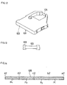
ribbon cartridge 101. This needs the frequent replacement of the ink-ribbon cartridge 101, which is troublesome. - The above problem will now be described more specifically with reference to Figure 14. In Figure 14, for example, a ribbon track area extending from a2 to b2 is used to print on a printing page P1, a ribbon track area extending from b2 to c2 is used to print on a printing page P2, a ribbon track area extending from c2 to d2 is used to print on a printing page P3, and a ribbon track area extending from d2 to e2 is used to print on a printing page P4. The endless type ink ribbon 105 loops back and the same ribbon track areas will be used again. In other words, the same ribbon track areas are always repeatedly used. Accordingly, the printing density quickly becomes lower, and the life of the ink-
ribbon cartridge 101 expires quickly. - The prior arts of the present invention are disclosed in, for example, Japanese Examined Patent Publication Nos. sho 40-28861 and sho 51-11528.
- It is, of course, known to provide multi-track printer ribbons and examples are shown in Xerox Disclosure Journal, vol. 4, no. 3, June 1979, page 419; US-A-4577198; and US-A-4402622. These documents describe relatively complex printers utilizing such multi-track ribbons.
- In accordance with one aspect of the present invention, a printer comprises an ink ribbon having a plurality of ribbon tracks of the same color arranged side by side across said ink ribbon; means for feeding print paper having a plurality of pages to be printed; and printing means for using an arbitrary one of said plurality of ribbon tracks to print on said print paper; and is characterised by determining means for determining whether any one of a plurality of operations is executing during printing, said plurality of operations including changing said plurality of pages to be printed, feeding a top of a new page of said plurality of pages to a printing position, and loading a new print paper; and ribbon track switching means for switching said ribbon tracks prior to printing on a new page when said determining means determines that one of said operations has been executed.
- In accordance with a second aspect of the present invention, a method of switching ribbon tracks of an ink ribbon comprises the step of switching a plurality of ribbon tracks of the same color of an ink ribbon, arranged side by side along said ink ribbon, when any one of a plurality of operations is executed during printing, said plurality of operations including changing a plurality of pages to be printed, feeding a top of a new page of said plurality of pages to a printing position, and loading a new print paper.
- The present invention provides a printer and a method of switching ribbon tracks of an ink ribbon, which will suppress a decrease in ink density to prolong the service life of a single ink-ribbon cartridge and to prevent the occurrence of a variation in printing quality on the same page.
- The paper to be used may be continuous paper or cut sheets of paper.
- If the paper in use is continuous paper, the number of steps of a stepping motor for feeding the paper may be managed or monitored to discriminate whether or not a printing page has been changed or an equivalent operation has been executed.
- In one example, an ink ribbon having a plurality of ribbon tracks of the same color is used and the ribbon tracks are properly switched from one to another in a printing operation, and, more particularly, the switching of the ribbon tracks is executed when a printing page is changed or an equivalent operation is executed. It is therefore possible to suppress a decrease in printing density to thereby prolong the service life of the ink-ribbon cartridge. Since the ribbon tracks are switched from one to another when a printing page is changed or an equivalent operation to the loading of new printing page is executed, thus inhibiting the switching of the ribbon tracks on the same page, the printing density on the same page becomes even and the printing quality can be improved.
-
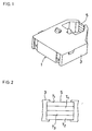
- Fig. 1 is a perspective view of an ink-ribbon cartridge according to one embodiment of the present invention;
- Fig. 2 is a front view showing the structure of a part of the ink-ribbon cartridge according to this embodiment;
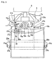
- Fig. 3 is a plan view showing a mechanism of switching the ribbon tracks of the ink-ribbon cartridge according to this embodiment;
- Fig. 4 is a side cross-sectional view showing the mechanism of switching the ribbon tracks of the ink-ribbon cartridge according to this embodiment;
- Fig. 5 is a side view showing the structure of a part of the mechanism of switching the ribbon tracks of the ink-ribbon cartridge according to this embodiment;
- Fig. 6 is a perspective view showing the structure of the part of the ribbon-track switching mechanism shown in Fig. 5;
- Fig. 7 is a partly plan view showing the mechanism of switching the ribbon tracks of the ink-ribbon cartridge according to this embodiment;
- Fig. 8 is a side view of a paper feeding mechanism used to explain the page management according to this embodiment;
- Figs. 9A and 9B are flowcharts illustrating how the ribbon tracks of an ink-ribbon cartridge are switched from one to another according to this embodiment;
- Fig. 10 is a diagram for explaining the order of the switching of the ribbon tracks of an ink-ribbon cartridge according to this embodiment;
- Fig. 11 is another diagram for explaining the order of the switching of the ribbon tracks of an ink-ribbon cartridge according to this embodiment;
- Fig. 12 is a perspective view of a conventional ink-ribbon cartridge;
- Fig. 13 is a front view showing the structure of a part of the conventional ink-ribbon cartridge; and
- Fig. 14 is a diagram showing how the ribbon tracks of the conventional ink-ribbon cartridge are used.
- A preferred embodiment of the present invention will now be described referring to Figs. 1 through 11. To begin with, the structure of an ink-
ribbon cartridge 1 used in this embodiment will be described referring to Figs. 1 and 2. The ink-ribbon cartridge 1 comprises acase 3, and an endlesstype ink ribbon 5 retained in thecase 3. Driving means for moving theink ribbon 5 in loop is disposed in thecase 3. As shown in Fig. 2, theink ribbon 5 is wide and consists of four ribbon tracks T1, T2, T3 and T4. Those ribbon tracks T1 to T4 are all black in color. - Switching means for switching the ribbon tracks T1 to T4 of the
ink ribbon 5 from one to another may take various structures. One example of the structure of this switching means is shown in Figs. 3 to 7. This structure, which is disclosed in Japanese Unexamined Patent Publication No. sho 63-254089, hasparallel guide bars carriage 9 is provided in such a way that it can move back and forth along theguide bars - A
lifting cam 11 is attached, rotatable in one direction, to the interior of thecarriage 9, as shown in Figs. 4 to 6. Acam 13 is formed like a step at the outer surface of thelifting cam 11. Fourpawls lifting cam 11 as shown in Fig. 7. Switchinglevers carriage 9. Elongatedgrooves switching levers pins grooves pins grooves switching levers pawls springs - An ink-
ribbon holder 25 is placed above thecarriage 9, and the ink-ribbon cartridge 1 described above is mounted on theholder 25. A pair ofpins ribbon holder 25. Thosepins holes angle members ribbon holder 25 is swingable around thepins - A
guide 33 protrudes from the surface of thecarriage 9, with alifting lever 35 fitted, movable up and down, on theguide 33 from above as shown in Fig. 4. Thislifting lever 35 is provided with aguide 35a, which clutches the step-shaped cam 13. Thelifting lever 35 has agroove 35b, as shown in Fig. 5, in which apin 25a protruding from the bottom of the ink-ribbon holder 25 is fitted. As shown in Fig. 7,stoppers carriage 9 moves beyond a printing area. Thestoppers carriage 9, and reference numeral "41" denotes a screen plate for the detectingmeans 39. - With the above structure, when the
carriage 9 moves beyond the normal printing area rightwards with the state shown in Fig. 7, the switchinglever 17b hits against thestopper 37b. At this time, the liftingcam 11 is positioned by the load of an index spring (not shown). When thecarriage 9 moves further rightwards in Fig. 7, the switchinglever 17b moves leftwards in the diagram against the urging force of thespring 23b. At this time, the switchinglever 17b pushes thepawl 15a of the liftingcam 11 to cause the liftingcam 11 to make a 1/4 turn. The power of the index spring to hold the liftingcam 11 is set stronger than thesprings - When the
carriage 9 moves leftwards in Fig. 5, the switchinglever 17b moves away from thestopper 37b and returns to the original position by the force of thespring 23b. At this time, the distal end of the switchinglever 17b moves over thepawl 15b. The liftingcam 11 makes a half turn when the above action is repeated twice, makes a 3/4 turn when that action is repeated three times, and finally makes a full turn when the above action is repeated four times. Every time the liftingcam 11 makes a 1/4 turn, the liftinglever 35 moves up or down via thecam 11 and the ink-ribbon holder 25 swings accordingly to shift the ink-ribbon cartridge 1 retained in theholder 25 in four steps. Consequently, the ribbon tracks T1, T2, T3 and T4 of theink ribbon 5 are sequentially switched from one to another. The ribbon-track switching mechanism described above is just one example, and another mechanism may of course be used. - As the switching of the ribbon tracks T1 to T4 of the
ink ribbon 5 is executed when printing page is changed in this embodiment, the page management of this embodiment will be described below with reference to the case where continuous paper is used. Fig. 8 illustrates a mechanism for feedingcontinuous paper 43. This mechanism has apush tractor 45, which comprises adrive pulley 47, a drivenpulley 49 and abelt 51 put around the drivingpulley 47 and the drivenpulley 49. A plurality ofpins 53 are attached at given pitches to thebelt 51. The drivingpulley 47 is given the rotational power from a stepping motor (not shown). Thecontinuous paper 43 has sheets ofpaper 43a of a given length connected by lines of perforations formed across thepaper 43 at the given lengths, and the sheets ofpaper 43a are folded at those lines of perforations. Thecontinuous paper 43 also has holes formed on both sides at given pitches where thepins 53 of thepush tractor 45 are to be fitted. - A
platen 55 is disposed in the paper feeding direction of thecontinuous paper 43. Thisplaten 55 is driven in synchronism with the driving of thepush tractor 45. Abail roller 57 is disposed above and facing theplaten 55 in Fig. 8. Thebail roller 57 presses the fedcontinuous paper 43 against theplaten 55. Apaper chute 59 is located under theplaten 55 in the diagram. Disposed on the opposite side of thepaper chute 59 to theplaten 55 arepinch rollers paper detecting means 65. Thepaper detecting means 65 is an optical detector, and senses the leading end of the fedcontinuous paper 43.Openings paper chute 59 where thepinch rollers pinch rollers - With the above structure, the every
sheet 43a of the continuous paper fed out by thepush tractor 45 comes between theplaten 55 and thepaper chute 59 to be put around theplaten 55. As thesheet 43a is put around theplaten 55, it is pressed against theplaten 55 by thebail roller 57. Under this situation, printing is performed by aprinting head 73 through an arbitrary one of the ribbon tracks T1 to T4 of theink ribbon 5. With regard to the page management, the number of steps (of the stepping motor) necessary to feed asingle sheet 43a defined between two lines of perforations is set previously. Changing to thenext sheet 43a can be detected by managing the number of steps. - The page management will be described in more details. At the time the
sheet 43a of thecontinuous paper 43 is fed, the current position of thatsheet 43a is always detected and memorized by accumulating the number of steps of the stepping motor. The number of steps of the stepping motor is previously set in accordance with the page length of everysheet 43a of thecontinuous paper 43. Pages change when the accumulated number of steps exceeds the stored number of steps corresponding to the page length of asingle sheet 43a. A top of form of thesheet 43a is detected in the following manner. The top of form is a reference position of a page for paper feed. When a printing page is changed or an equivalent operation is executed, paper is fed until the top of form of the next page comes to a printing position. If thesheet 43a is already set (or present at the detecting position of the paper detecting means 65) when the printer is activated, the current position is considered as the top of form. If thesheet 43a is not present at the detecting position upon activation of the printer, on the other hand, when the detection result changes from "no paper" to "paper present" during the feeding of thesheet 43a, i.e., when thepaper detecting means 65 detects the leading end of thesheet 43a, thesheet 43a is fed by a predetermined distance corresponding to the distance between thepaper detecting means 65 and theprinting head 73. This position is considered as the top of form. By counting the number of steps of the stepping motor, it is possible to easily discriminate whether or not thesheet 43a has been fed by the predetermined distance. - The page management will now be described more specifically. A vertical location counter (hereinafter referred to as "VLC") is provided in the page managing portion of the printer. This VLC is accomplished by a specific area in a RAM serving as a counter. The VLC counts and accumulates the number of steps as the
sheet 43a is fed. Suppose that the page length of asingle sheet 43a of thecontinuous paper 43 is 10 inches and this 10-inch sheet 43a is fed out in 3600 (10 x 360 steps/inch) steps. In this case, pages change when the accumulation result of the number of steps of asingle sheet 43a of thecontinuous paper 43 exceeds 3600 steps from the top of form. When the accumulated number of steps exceeds 3600 steps, the VLC is reset and the counting will start from 0, so that the paper feeding position of the nextsingle sheet 43a can be detected. In other words, the current position of asingle sheet 43a can always be monitored by recognizing any number of steps, from 0 to 3559. The number of steps "3600" is just one example, and may be set to any number. - With the above description in mind, the operation of the printer will now be described along the flowchart given in Figs. 9A and 9B. First, as an initialization, a track change request flag for switching the ribbon tracks T1 to T4 of the
ink ribbon 5 from one to another is set off (step S1). This track change request flag is set on or off at one address in the aforementioned RAM by using one bit of one byte at that address. Next, the page length is set (step S2). More specifically, an operation register A (VLC) for controlling the page length is provided in the RAM and the number of steps corresponding to the page length of thesheet 43a is set in the register A. Through the above steps, the initialization is completed. - Then, printing data is set (step S3) to make the printer ready to print, and the flow advances to step S4. In this step S4, the ON/OFF status of the track change request flag is discriminated. As the track change request flag is set off in the aforementioned step S1, it is still off in the first discrimination in step S4, so that the flow goes to step S5 to execute printing. When printing of one line is complete in step S5, a line feed is executed (step S6). When a line feed is executed, a predetermined number of steps corresponding to one line is subtracted from the preset number of steps corresponding to the page length in the register A (step S7).
- Then, the flow goes to step S8 where the remaining number of steps in the register A is determined. If there is any steps left, the flow returns to step S3 and the above-described operation will be repeated. If it is determined that there is no steps left, on the other hand, the flow advances to step S9. In this step S9, the page length in the register A is reset to the number of steps corresponding to the page length. This page management has already been described above. In the next step S10, the track change request flag is set on. The printer is now ready for switching the ribbon tracks when a change of page is executed. From that point, the flow moves to step S3 to set printing data again. This is to make the printer ready to print the first line of the next page. Then, the flow goes to step S4 where the ON/OFF status of the track change request flag is discriminated.
- As the track change request flag is on this time, the flow advances to step S11. In this step S11, the switching of the ribbon tracks T1, T2, T3 and T4 from one to another is executed. When this ribbon-track switching is complete, the track change request flag is set off before the flow goes to step S5. The printing, the page change, and the switching of the ribbon tracks T1-T4 of the
ink ribbon 5 are conducted in the above-mentioned manner. - The switching of the ribbon tracks T1-T4 of the
ink ribbon 5 is performed not only by the page change during printing but also by an equivalent operation. As shown in Fig. 9B, when the top of form of the next page is executed in response to a command (a form-feed (FF) code which means that one page has ended and paper is fed until the top of form of the next page comes to the printing position) in step S13, the flow goes to step S9 and thereafter the switching of the ribbon tracks T1-T4 of theink ribbon 5 will be executed through the same steps as described above. Even when thesheet 43a is loaded by the feeding of thecontinuous paper 43 or a cut sheet of paper is loaded (step S14), the flow goes to step S9 and thereafter the switching of the ribbon tracks T1-T4 of theink ribbon 5 will be executed through the same steps as described above. - When the switching of the ribbon tracks T1-T4 of the
ink ribbon 5 is executed through the above-described steps, the ribbon tracks T1 to T4 are used as shown in Figs. 10 and 11. Fig. 10 illustrates how theink ribbon 5 is used when four pages are continuously printed starting from the ribbon track T1. The switching of the ribbon tracks T1-T4 of theink ribbon 5 is executed in the sequence shown in Fig. 10. That is, the ribbon track T1 is used first, the ribbon track T2 is used next, the ribbon track T3 is used next, and the ribbon track T4 is used finally. - Referring to Fig. 11, the first page is printed using the area of the ribbon track T1 from a1 to b1. The position b1 is where pages change from the first page to the second page and where the ribbon track of the ink ribbon changes from T1 to T2. The second page is printed using the area of the ribbon track T2 from b1 to c1. The position c1 is where pages change from the second page to the third page and where the ribbon track of the ink ribbon changes from T2 to T3. Likewise, the third page is printed using the area of the ribbon track T3 from c1 to d1. The position d1 is where pages change from the third page to the fourth page and where the ribbon track of the ink ribbon changes from T3 to T4. The fourth page is printed using the area of the ribbon track T4 from d1 to e1.
- This embodiment has the following advantages. First, the lowering of the ink density of the
ink ribbon 5 can be suppressed, thus improving the printing quality as well as prolonging the service life of the ink-ribbon cartridge 1. This avoids frequent, troublesome replacement of the ink-ribbon cartridge. This advantage is achieved by designing theink ribbon 5 of the ink-ribbon cartridge to have a plurality of ribbon tracks (four in this embodiment) T1, T2, T3 and T4, and changing those four ribbon tracks from one to another page by page. In particular, since the switching of the ribbon tracks T1-T4 of theink ribbon 5 from one to another is conducted page by page and the ribbon-track switching within the same page is inhibited, the printing density will not significantly vary within the same page. Therefore, the printing quality is also improved, and the user will not particularly be bothered by uneven printing density. - Although only one embodiment of the present invention has been described herein, it should be apparent to those skilled in the art that the present invention may be embodied in many other specific forms.
- For instance, the number of the ribbon tracks of the ink ribbon is not limited to four, but may be two, three, or five or greater. Further, the printing color is not limited to black and may take another color. The mechanism for switching the ribbon tracks is in no way restrictive to the illustrated one.
- Although the foregoing description of this embodiment has been given with reference to the case where continuous paper is used, this invention can also applied to the case of using cut sheets of paper. The page management of cut sheets of paper is executed by detecting the leading end and trailing end of each sheet as follows. After the leading end of a cut sheet is detected, the sheet is fed by a predetermined distance so that the leading end reaches the printing position. This action is equivalent to the setting of the top of form of continuous paper, and printing will start at that position. Then, the trailing end of the cut sheet is detected. Even after the detection of the trailing end, this cut sheet still has a predetermined length of a printable area. The predetermined distance and the predetermined length are both detected by counting the number of steps. The cut sheet is discharged after a predetermined amount of printing is completed. If the printer receives the FF code during printing on one page or a paper discharge command is generated by the manipulation of a certain switch on the operating panel, the paper will be discharged compulsively. When the FF code is received, paper loading follows the paper ejection. Paper loading is carried out when the printer has received printing data. Therefore, if the printer receives new printing data in a paper empty state, or if the printer still has printing data that has left unprinted on the previous page, paper loading is carried out. Paper loading is also executed when a feed switch is operated.
Claims (5)
- A printer for printing on a plurality of pages, comprising:an ink ribbon (5) having a plurality of ribbon tracks (T1, T2, T3, T4) of the same color arranged side by side across said ink ribbon (5);means for feeding print paper having a plurality of pages to be printed; andprinting means for using an arbitrary one of said plurality of ribbon tracks (T1, T2, T3, T4) to print on said print paper; characterised bydetermining means for determining whether any one of a plurality of operations is executed during printing, said plurality of operations including changing said plurality of pages to be printed, feeding a top of a new page of said plurality of pages to a printing position, and loading a new print paper; andribbon track switching means for switching said ribbon tracks (T1, T2, T3, T4) prior to printing on a new page when said determining means determines that one of said operations has been executed.
- A method of switching ribbon tracks of an ink ribbon, comprising the step of switching a plurality of ribbon tracks (T1, T2, T3, T4) of the same color of an ink ribbon (5), arranged side by side along said ink ribbon (5), when any one of a plurality of operations is executed during printing, said plurality of operations including changing a plurality of pages to be printed, feeding a top of a new page of said plurality of pages to a printing position, and loading a new print paper.
- The method as claimed in claim 2, wherein paper to be used is a continuous sheet of paper (43) or cut sheets of paper.
- The method as claimed in claim 3, wherein with continuous paper (43) in use, the number of steps of a stepping motor for feeding said continuous paper (43) is managed to discriminate whether or not a printing page has been changed or an equivalent operation has been executed.
- A method according to any of claims 2 to 4, the method being performed on a printer according to claim 1.
Applications Claiming Priority (2)
| Application Number | Priority Date | Filing Date | Title |
|---|---|---|---|
| JP322705/92 | 1992-11-06 | ||
| JP4322705A JP2630541B2 (en) | 1992-11-06 | 1992-11-06 | Ink ribbon ribbon track switching method |
Publications (3)
| Publication Number | Publication Date |
|---|---|
| EP0596647A2 EP0596647A2 (en) | 1994-05-11 |
| EP0596647A3 EP0596647A3 (en) | 1994-09-07 |
| EP0596647B1 true EP0596647B1 (en) | 1997-08-06 |
Family
ID=18146706
Family Applications (1)
| Application Number | Title | Priority Date | Filing Date |
|---|---|---|---|
| EP93308566A Expired - Lifetime EP0596647B1 (en) | 1992-11-06 | 1993-10-27 | Ink ribbon and its method of operation in a printer |
Country Status (4)
| Country | Link |
|---|---|
| US (1) | US5451112A (en) |
| EP (1) | EP0596647B1 (en) |
| JP (1) | JP2630541B2 (en) |
| DE (1) | DE69312860T2 (en) |
Families Citing this family (13)
| Publication number | Priority date | Publication date | Assignee | Title |
|---|---|---|---|---|
| AT406429B (en) * | 1998-09-17 | 2000-05-25 | Care Tec Gmbh | DEVICE FOR PRODUCING TACTILE DETECTABLE ELEMENTS |
| JP1579614S (en) * | 2017-01-25 | 2017-06-19 | ||
| JP1579484S (en) * | 2017-01-25 | 2017-06-19 | ||
| JP1579479S (en) * | 2017-01-25 | 2017-06-19 | ||
| USD843013S1 (en) * | 2017-01-25 | 2019-03-12 | Hamamatsu Photonics K.K. | Substrates for spectroscopic analysis |
| JP1579483S (en) * | 2017-01-25 | 2017-06-19 | ||
| JP1579616S (en) * | 2017-01-25 | 2017-06-19 | ||
| JP1579613S (en) * | 2017-01-25 | 2017-06-19 | ||
| JP1579481S (en) * | 2017-01-25 | 2017-06-19 | ||
| JP1579612S (en) * | 2017-01-25 | 2017-06-19 | ||
| JP1579485S (en) * | 2017-01-25 | 2017-06-19 | ||
| JP1579480S (en) * | 2017-01-25 | 2017-06-19 | ||
| JP1583356S (en) * | 2017-01-25 | 2017-08-07 |
Family Cites Families (12)
| Publication number | Priority date | Publication date | Assignee | Title |
|---|---|---|---|---|
| JPS543570B2 (en) * | 1974-07-19 | 1979-02-24 | ||
| JPS5525107A (en) * | 1978-08-09 | 1980-02-22 | Nec Corp | Printer |
| JPS5933319B2 (en) * | 1980-04-15 | 1984-08-15 | ブラザー工業株式会社 | Ink ribbon drive device |
| JPS5816881A (en) * | 1981-07-24 | 1983-01-31 | Fujitsu Ltd | Driving system of printer |
| JPS6046285A (en) * | 1983-08-24 | 1985-03-13 | Alps Electric Co Ltd | Thermal printer |
| US4606661A (en) * | 1984-05-07 | 1986-08-19 | International Business Machines Corporation | Proportional vertical and horizontal ribbon tracking for impact printers |
| JPS61175070A (en) * | 1985-01-31 | 1986-08-06 | Fujitsu Ltd | Printer |
| DE3607999C1 (en) * | 1986-03-11 | 1987-10-08 | Mannesmann Ag | Ribbon device for printers, in particular for matrix printers |
| JPS62256683A (en) * | 1986-04-30 | 1987-11-09 | Toshiba Corp | Color printer |
| DE3890244C2 (en) * | 1987-04-13 | 1992-05-27 | Star Seimitsu K.K., Shizuoka, Jp | |
| JP2786916B2 (en) * | 1989-12-22 | 1998-08-13 | 三洋電機株式会社 | Ink ribbon shift control method |
| JPH0428861A (en) * | 1990-05-25 | 1992-01-31 | Hitachi Koki Co Ltd | Film forming device using hollow cathode electron gun |
-
1992
- 1992-11-06 JP JP4322705A patent/JP2630541B2/en not_active Expired - Fee Related
-
1993
- 1993-10-27 DE DE69312860T patent/DE69312860T2/en not_active Expired - Fee Related
- 1993-10-27 EP EP93308566A patent/EP0596647B1/en not_active Expired - Lifetime
-
1994
- 1994-10-13 US US08/322,372 patent/US5451112A/en not_active Expired - Fee Related
Also Published As
| Publication number | Publication date |
|---|---|
| DE69312860D1 (en) | 1997-09-11 |
| EP0596647A3 (en) | 1994-09-07 |
| US5451112A (en) | 1995-09-19 |
| EP0596647A2 (en) | 1994-05-11 |
| JPH06143777A (en) | 1994-05-24 |
| JP2630541B2 (en) | 1997-07-16 |
| DE69312860T2 (en) | 1998-03-12 |
Similar Documents
| Publication | Publication Date | Title |
|---|---|---|
| US5451112A (en) | Printer and method of switching ribbon tracks of ink ribbon | |
| US4616236A (en) | Image forming apparatus with color transfer material | |
| CN102085763B (en) | Image forming apparatus and control method | |
| JPH071783A (en) | Ribbon, printer and cassette | |
| US5538351A (en) | Thermal transfer printer and ribbon change structure | |
| JPS60222278A (en) | Printing ribbon cartridge and manufacture thereof | |
| JP2939400B2 (en) | Thermal transfer printer and ribbon cassette | |
| EP0521521B1 (en) | Method and apparatus for thermal transfer recording and ink paper cassette therefor | |
| JP4843830B2 (en) | Printer and print control method | |
| EP0661165B1 (en) | Recording apparatus | |
| US5135321A (en) | Unified paper path printer with automatic parking feature | |
| JPH0127864B2 (en) | ||
| US5529407A (en) | Image recording apparatus | |
| US6412995B2 (en) | Printing apparatus and platen with a plurality of impact surfaces | |
| EP0293243B1 (en) | Printer | |
| JP2001080065A (en) | Ink-jet image-forming apparatus | |
| JPH0624586A (en) | Universal paper feeding cassette | |
| KR0134323B1 (en) | A4 / A5 / A6 paper sublimation printer device and its printing method | |
| EP0454092A2 (en) | Ribbon adapter and ribbon cassette capable of mounting the ribbon adapter and recording apparatus | |
| JP3844202B2 (en) | Paper transport method for dot printer | |
| JP2008183870A (en) | Inkjet recording device | |
| KR100234428B1 (en) | How to automatically detect and clear paper jams | |
| JPS61225082A (en) | Paper feeding device | |
| JPS61220874A (en) | Automatic paper feeding system for recording devices | |
| JPS61220886A (en) | recording device |
Legal Events
| Date | Code | Title | Description |
|---|---|---|---|
| PUAI | Public reference made under article 153(3) epc to a published international application that has entered the european phase |
Free format text: ORIGINAL CODE: 0009012 |
|
| AK | Designated contracting states |
Kind code of ref document: A2 Designated state(s): DE FR GB NL |
|
| PUAL | Search report despatched |
Free format text: ORIGINAL CODE: 0009013 |
|
| AK | Designated contracting states |
Kind code of ref document: A3 Designated state(s): DE FR GB NL |
|
| 17P | Request for examination filed |
Effective date: 19950303 |
|
| 17Q | First examination report despatched |
Effective date: 19960301 |
|
| GRAG | Despatch of communication of intention to grant |
Free format text: ORIGINAL CODE: EPIDOS AGRA |
|
| GRAH | Despatch of communication of intention to grant a patent |
Free format text: ORIGINAL CODE: EPIDOS IGRA |
|
| GRAH | Despatch of communication of intention to grant a patent |
Free format text: ORIGINAL CODE: EPIDOS IGRA |
|
| GRAA | (expected) grant |
Free format text: ORIGINAL CODE: 0009210 |
|
| AK | Designated contracting states |
Kind code of ref document: B1 Designated state(s): DE FR GB NL |
|
| PG25 | Lapsed in a contracting state [announced via postgrant information from national office to epo] |
Ref country code: NL Free format text: LAPSE BECAUSE OF FAILURE TO SUBMIT A TRANSLATION OF THE DESCRIPTION OR TO PAY THE FEE WITHIN THE PRESCRIBED TIME-LIMIT Effective date: 19970806 Ref country code: FR Free format text: LAPSE BECAUSE OF FAILURE TO SUBMIT A TRANSLATION OF THE DESCRIPTION OR TO PAY THE FEE WITHIN THE PRESCRIBED TIME-LIMIT Effective date: 19970806 |
|
| REF | Corresponds to: |
Ref document number: 69312860 Country of ref document: DE Date of ref document: 19970911 |
|
| EN | Fr: translation not filed | ||
| NLV1 | Nl: lapsed or annulled due to failure to fulfill the requirements of art. 29p and 29m of the patents act | ||
| PLBE | No opposition filed within time limit |
Free format text: ORIGINAL CODE: 0009261 |
|
| 26N | No opposition filed | ||
| PGFP | Annual fee paid to national office [announced via postgrant information from national office to epo] |
Ref country code: DE Payment date: 20001023 Year of fee payment: 8 |
|
| PGFP | Annual fee paid to national office [announced via postgrant information from national office to epo] |
Ref country code: GB Payment date: 20001025 Year of fee payment: 8 |
|
| PG25 | Lapsed in a contracting state [announced via postgrant information from national office to epo] |
Ref country code: GB Free format text: LAPSE BECAUSE OF NON-PAYMENT OF DUE FEES Effective date: 20011027 |
|
| REG | Reference to a national code |
Ref country code: GB Ref legal event code: IF02 |
|
| GBPC | Gb: european patent ceased through non-payment of renewal fee |
Effective date: 20011027 |
|
| PG25 | Lapsed in a contracting state [announced via postgrant information from national office to epo] |
Ref country code: DE Free format text: LAPSE BECAUSE OF NON-PAYMENT OF DUE FEES Effective date: 20020702 |