EP0596574B1 - Method for securing a removable connector on a fixed connector and a locking element therefor - Google Patents
Method for securing a removable connector on a fixed connector and a locking element therefor Download PDFInfo
- Publication number
- EP0596574B1 EP0596574B1 EP93203061A EP93203061A EP0596574B1 EP 0596574 B1 EP0596574 B1 EP 0596574B1 EP 93203061 A EP93203061 A EP 93203061A EP 93203061 A EP93203061 A EP 93203061A EP 0596574 B1 EP0596574 B1 EP 0596574B1
- Authority
- EP
- European Patent Office
- Prior art keywords
- connector
- locking
- locking element
- wall
- locking members
- Prior art date
- Legal status (The legal status is an assumption and is not a legal conclusion. Google has not performed a legal analysis and makes no representation as to the accuracy of the status listed.)
- Expired - Lifetime
Links
Images

Classifications
-
- H—ELECTRICITY
- H01—ELECTRIC ELEMENTS
- H01R—ELECTRICALLY-CONDUCTIVE CONNECTIONS; STRUCTURAL ASSOCIATIONS OF A PLURALITY OF MUTUALLY-INSULATED ELECTRICAL CONNECTING ELEMENTS; COUPLING DEVICES; CURRENT COLLECTORS
- H01R13/00—Details of coupling devices of the kinds covered by groups H01R12/70 or H01R24/00 - H01R33/00
- H01R13/62—Means for facilitating engagement or disengagement of coupling parts or for holding them in engagement
- H01R13/639—Additional means for holding or locking coupling parts together, after engagement, e.g. separate keylock, retainer strap
- H01R13/6395—Additional means for holding or locking coupling parts together, after engagement, e.g. separate keylock, retainer strap for wall or panel outlets
-
- H—ELECTRICITY
- H01—ELECTRIC ELEMENTS
- H01R—ELECTRICALLY-CONDUCTIVE CONNECTIONS; STRUCTURAL ASSOCIATIONS OF A PLURALITY OF MUTUALLY-INSULATED ELECTRICAL CONNECTING ELEMENTS; COUPLING DEVICES; CURRENT COLLECTORS
- H01R13/00—Details of coupling devices of the kinds covered by groups H01R12/70 or H01R24/00 - H01R33/00
- H01R13/62—Means for facilitating engagement or disengagement of coupling parts or for holding them in engagement
Definitions
- the present invention relates to the joining together of two complementary connectors, and in particular of DB-type electric connectors that are frequently used in computer systems.
- Fig. 1 represents a conventional DB-type male connector 5.
- This connector includes a body 6 provided with a rectangular connection plane 10.
- the central area of plane 10 includes a plurality of pins 11 extending perpendicularly to plane 10.
- a metallic shielding and protection wall 12 surrounds the plurality of pins 11.
- Cylinders 13 include a circumferential groove 13-1 in the vicinity of their distal extremity.
- peg is to be construed as a cylinder 13 provided with this circumferential groove 13-1.
- the pegs 13 are part of a locking system for fixing the male connector to a female connector.
- Pegs 13, in a conventional locking system cooperate with a locking element that is mounted so as to slide longitudinally, across the body of the female connector.
- the locking element is formed by a strip element whose extremities are folded against the face oriented towards the plug. Each folded portion is provided with a fork, one opening towards the middle of the strip element, the second opening away from the strip element.
- the locking element Before plugging the male conector into the female connector, the locking element is displaced to one side to allow the pegs 13 to pass through the forks; then the locking element is slid into a locking position where the forks imprison the grooves of pegs 13.
- the sliding locking element is retained against the body of the female connector by two screws screwed into the body of this connector.
- the heads of these screws are located between the main part of the locking element and the folded parts and serve as an abutment for the pegs 13 to determine the matching position between the grooves of pegs 13 and the forks of the sliding locking element.
- the fixed connector protrudes from a plate or the wall of an electronic apparatus casing.
- the plate is provided with an aperture large enough to accommodate the body of the fixed connector with its locking element and this does not allow the fixed connecter to be fixed to the plate.
- the fixed connector is secured at its back to a printed circuit, for example by means of soldered pins and/or by screws that retain the sliding locking element and then passss through the connector body.
- the fixed connector is also secured to the above-mentioned plate by the screws holding the sliding locking element.
- the plate is then provided with an aperture through which only the active part of the connector protrudes, the plate being interposed between the sliding locking element and the body of the connector.
- a drawback of this solution is that the removable connector, when in its final position, is not fully plugged home in the fixed connector. Indeed, the screws holding the sliding locking element , which serve as an abutment for the pegs 13, are separated from the fixed connector by the thickness of the plate. This drawback could be solved by shortening the pegs to account for the thickness of the plate. This, however, would raise the obvious problem that standard connectors could no longer be used but, on the contrary, a large range of specific connectors would have to be provided because the plates have various thicknesses.
- US patent specification US-A-1,598,038 discloses an electrical fixture in which an electrical plug is engageable in a socket.
- the plug can be locked in position by sliding a member carried by the plug to engage hooks of the member behind a support plate on which the socket is mounted.
- a connector arrangement comprising:
- the invention also provides a method for fixing a removable connector, provided with first locking members, on a complementary fixed connector provided in a wall, including the steps of: providing second locking members on the wall; placing a locking element between the removable connector and the fixed connector, this locking element being provided with third and fourth locking members, respectively complementary to the first and second locking members; engaging the removable connector with the fixed connector; and sliding the locking element so that its locking members cooperate in locking relation with the locking members of the removable connector and the wall.
- a locking element according to the invention is intended to cooperate with a removable connector, such as that of Fig. 1, provided with locking pegs 13.
- Fig. 2A is a perspective view of an embodiment of a locking element according to the invention.
- the locking element can be easily fabricated by folding a punched metal plate or sheet, shown before its folding in Fig. 2B.
- the locking element includes a rectangular plane 22 provided with a central rectangular aperture 23 for permitting the connection pins 11 and the protection wall 12 of a male connector to pass towards the associated female connector.
- Two slots, 25 and 26, open into the shorter sides of aperture 23, approximately in the middle of these sides.
- the width of slots 25 and 26 is approximately equal to the smallest diameter of pegs 13 (the diameter at their circumferential groove 13-1).
- one of the slots, 26, includes at its blind end a circular portion 27 having a diameter approximately equal to the largest diameter of pegs 13.
- the areas where slot 25 opens into aperture 23 are bevelled as shown by 25-1.
- the long edges of the rectangular plane 22 are provided with hooks extending first perpendicularly to plane 22, then parallel to plane 22 in the direction of slot 26.
- the hooks are formed by punched sheet portions that are folded at 90° to plane 22.
- one of the long edges of plane 22 includes two hooks 30; the second edge has a single hook 31 for reasons that are explained hereinafter, which depend on the specific configuration of the described locking element.
- Hooks 30, 31 are designed to enter slots (described later) of a wall through which protrudes a fixed connector with which the removable connector is to be engaged.
- locking element 20 includes walls extending from the edges of plane 22 on the other side of this plane with respect to hooks 30, 31.
- Two walls 32 extend from the shorter edges of plane 22, a wall 33 extends from the upper long edge of plane 22 between hooks 30, and a large wall 34 extends from the lower long edge of plane 22 and occupies the whole length of this edge.
- These walls 32-34 are formed by sheet portions that are folded at 90° to plane 22. As shown in Fig. 2B, before folding, hook 31 extends from the wall 34 and it attains its 90° position to plane 22 as a result of the folding of wall 34.
- the large wall 34 serves as a support wall for the body of the removable connector and provides a good grip of the removable connector and locking element. Walls 32 and 33 are useful for pre-positioning of the connector body.
- the locking element 20 can be symmetric with respect to a longitudinal axis and can include four hooks. If wall 34 is provided, the upper hooks 30 can be placed closer to each other so as to permit the provision of two lower corresponding hooks 31 in aperture 23. However, bringing the hooks closer together decreases the efficacy of the locking element. To simplify manufacture, the lower hook 31 need not be provided. In this case, the locking element is preferably used so that hooks 30 are at the top. Indeed, in most cases, the body of the connector lies by gravity on the support wall 34, and it is then the upper hooks 30 that are the most stressed.
- a lower hook 31 is provided, it is preferably symmetrically disposed relative to an upper hook 30 with respect to the center of the locking element 20. With four symmetric slots placed around the fixed connector, this solution enables the lock 20 to be used both in a first position and in a position rotated 180° about the axis of the connectors.
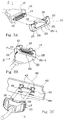
- Figs. 3A, 3B, and 3C illustrate three successive steps for fixing a removable connector wiht its locking element according to the invention.
- the illustrated removable connector 5 to be fixed is a male connector provided with lock pegs 13.
- the connector 5 could also be a female connector, provided with pegs 13, to be engaged with a fixed male connector.
- a locking element 20 according to the invention, provided for example with two hooks 30, is held by a user near the connector 5 so that hooks 30 are oriented away from connector 5 and so as to approximately match slots 25 and 26 with pegs 13.
- the hole 27 at the blind end of slot 26 is slid over one peg 13.
- the length of aperture 23 is such that the end of the second peg 13 passes without hinderance where slot 25 opens in aperture 23.
- the areas where slot 25 opens in aperture 23 can be bevelled.
- the length of aperture 23 can be selected such that the peg 13 associated with slot 25 is partially engaged into slot 25 (in the bevels), which enables pre-positioning of the locking element 20 before the locking operation.
- Fig. 3C the assembly of locking element 20 and connector 5, arranged as shown in Fig. 3B, is held so as to face a female connector 40 passing through a casing wall 42. Sufficient clearance between wall 42 and connector 40 is provided to allow the passage there through of the protection wall 12 of connector 5.
- two slots 43 are provided in wall 42 above socket 40. Slots 43 are parallel to a longitudinal axis of the locking element 20 and correspond to the upper hooks 30 in the given example.
- Two additional slots 44 disposed symmetrically with respect to the center of connector 40, are also provided in wall 42 so as also to be able to fix connector 5 after turning the locking element 20 upside-down (hooks 30 then being at the bottom of lock 20). Additionally, the four symmetrical slots 43, 44 allow, independently of the number of hooks that are provided (2, 3 or 4), the locking element 20 to be turned upside-down.
- hooks 30 On engaging the male connector 5 into the female connector 40, hooks 30 enter slots 43.
- the locking element 20 is shifted in the direction indicated by arrow F (towards the right in Fig. 3C).
- slots 25 and 26 imprison the associated pegs 13, and hooks 30 are locked at one end of their respective slots (right-hand portion in Fig. 3C).
- the connector 5 is thus fixed to wall 42 and not to the complementary connector 40. Any force transmitted to the connector 5 is transmitted through the locking element 20 to the wall 42 which is much more rigid than the connector 40.
- countersunk screws 45 fix the connector 40 to the wall 42 by means of threads conventionally provided in the connector 40.
- the locking element can be cast, which would enable the four fixing hooks to be more easily provided.
- any alternative locking means can be provided, as, for example, pegs integral with locking element 20, and cooperating with slots in the wall, or the other way around.
Description
- The present invention relates to the joining together of two complementary connectors, and in particular of DB-type electric connectors that are frequently used in computer systems.
- Fig. 1 represents a conventional DB-
type male connector 5. This connector includes abody 6 provided with arectangular connection plane 10. The central area ofplane 10 includes a plurality ofpins 11 extending perpendicularly to plane 10. A metallic shielding andprotection wall 12 surrounds the plurality ofpins 11. On both sides of the assembly ofpins 11, in the vicinity of the shorter sides of therectangular plane 10, two fixedcylinders 13 are provided, extending perpendicularly to plane 10.Cylinders 13 include a circumferential groove 13-1 in the vicinity of their distal extremity. Hereinafter, "peg" is to be construed as acylinder 13 provided with this circumferential groove 13-1. - The
pegs 13 are part of a locking system for fixing the male connector to a female connector.Pegs 13, in a conventional locking system, cooperate with a locking element that is mounted so as to slide longitudinally, across the body of the female connector. The locking element is formed by a strip element whose extremities are folded against the face oriented towards the plug. Each folded portion is provided with a fork, one opening towards the middle of the strip element, the second opening away from the strip element. Before plugging the male conector into the female connector, the locking element is displaced to one side to allow thepegs 13 to pass through the forks; then the locking element is slid into a locking position where the forks imprison the grooves ofpegs 13. The sliding locking element is retained against the body of the female connector by two screws screwed into the body of this connector. The heads of these screws are located between the main part of the locking element and the folded parts and serve as an abutment for thepegs 13 to determine the matching position between the grooves ofpegs 13 and the forks of the sliding locking element. - Generally, the fixed connector protrudes from a plate or the wall of an electronic apparatus casing. In most cases, the plate is provided with an aperture large enough to accommodate the body of the fixed connector with its locking element and this does not allow the fixed connecter to be fixed to the plate. In this case, the fixed connector is secured at its back to a printed circuit, for example by means of soldered pins and/or by screws that retain the sliding locking element and then passss through the connector body.
- Since the removable connector is only fixed to the socket, a drawback of this assembly is that all the forces applied to the connector are transmitted to the fixed connector. Such forces, amplified by a lever effect, are also transmitted to the means securing the fixed connector to the printed circuit, which rapidly leads to damage of the secural means and/or the printed circuit.
- In some cases, the fixed connector is also secured to the above-mentioned plate by the screws holding the sliding locking element. The plate is then provided with an aperture through which only the active part of the connector protrudes, the plate being interposed between the sliding locking element and the body of the connector. A drawback of this solution is that the removable connector, when in its final position, is not fully plugged home in the fixed connector. Indeed, the screws holding the sliding locking element , which serve as an abutment for the
pegs 13, are separated from the fixed connector by the thickness of the plate. This drawback could be solved by shortening the pegs to account for the thickness of the plate. This, however, would raise the obvious problem that standard connectors could no longer be used but, on the contrary, a large range of specific connectors would have to be provided because the plates have various thicknesses. - US patent specification US-A-1,598,038 discloses an electrical fixture in which an electrical plug is engageable in a socket. The plug can be locked in position by sliding a member carried by the plug to engage hooks of the member behind a support plate on which the socket is mounted.
- It is an object of the invention to provide a sliding locking system for fixing a standard removable connector to a standard fixed connector which enables the forces transmitted by the removable connector to the fixed connector to be reduced.
- According to one aspct of the present invention, there is provided a connector arrangement comprising:
- -- a removable connector provided with first locking members;
- -- a structure provided with a wall having second locking members;
- -- a fixed connector provided in said wall, the fixed connector being fixed to said structure and said removable connector being engagable with said fixed connector by movement theretowards along a predetermined axis of engagement; and
- -- a locking element for locking the removable connector in engagement with the fixed connector, said locking element being separable from said connectors when the connectors are disengaged from each other;
- The invention also provides a method for fixing a removable connector, provided with first locking members, on a complementary fixed connector provided in a wall, including the steps of: providing second locking members on the wall; placing a locking element between the removable connector and the fixed connector, this locking element being provided with third and fourth locking members, respectively complementary to the first and second locking members; engaging the removable connector with the fixed connector; and sliding the locking element so that its locking members cooperate in locking relation with the locking members of the removable connector and the wall.
- The foregoing and other objects, features, aspects and advantages of the invention will become apparent from the following detailed description of the present invention which should be read in conjunction with the accompanying drawings.
-
- Fig. 1, described above, represents a removable male connector provided with pegs for cooperating with a conventional locking element included in a female connector;
- Figs. 2A and 2B represent an embodiment of a locking element, according to the invention, fabricated by punching and folding a metal sheet; and
- Figs. 3A, 3B and 3C illustrate three successive steps for fixing a removable connector by means of a locking element according to the invention.
- A locking element according to the invention is intended to cooperate with a removable connector, such as that of Fig. 1, provided with
locking pegs 13. - Fig. 2A is a perspective view of an embodiment of a locking element according to the invention. The locking element can be easily fabricated by folding a punched metal plate or sheet, shown before its folding in Fig. 2B.
- The locking element includes a
rectangular plane 22 provided with a centralrectangular aperture 23 for permitting theconnection pins 11 and theprotection wall 12 of a male connector to pass towards the associated female connector. Two slots, 25 and 26, open into the shorter sides ofaperture 23, approximately in the middle of these sides. The width ofslots circular portion 27 having a diameter approximately equal to the largest diameter ofpegs 13. The areas whereslot 25 opens intoaperture 23 are bevelled as shown by 25-1. - The long edges of the
rectangular plane 22 are provided with hooks extending first perpendicularly to plane 22, then parallel toplane 22 in the direction ofslot 26. The hooks are formed by punched sheet portions that are folded at 90° to plane 22. As shown, one of the long edges ofplane 22 includes twohooks 30; the second edge has asingle hook 31 for reasons that are explained hereinafter, which depend on the specific configuration of the described locking element.Hooks - Additionally,
locking element 20 includes walls extending from the edges ofplane 22 on the other side of this plane with respect tohooks walls 32 extend from the shorter edges ofplane 22, awall 33 extends from the upper long edge ofplane 22 betweenhooks 30, and alarge wall 34 extends from the lower long edge ofplane 22 and occupies the whole length of this edge. These walls 32-34 are formed by sheet portions that are folded at 90° to plane 22. As shown in Fig. 2B, before folding,hook 31 extends from thewall 34 and it attains its 90° position to plane 22 as a result of the folding ofwall 34. - It will be noted, in Fig. 2B, that the
lower hook 31 is punched in theaperture 23 and is at the same level as one of the upper hooks 30. The secondupper hook 30 overlaps a portion ofaperture 23 and a solid portion ofplane 22; with this configuration, alower hook 31 cannot be punched inaperture 23, at the same level. - The
large wall 34 serves as a support wall for the body of the removable connector and provides a good grip of the removable connector and locking element.Walls - Various alternative forms for the punched and folded locking
element 20 will be apparent to those skilled in the art. If thesupport wall 34 is not provided, the lockingelement 20 can be symmetric with respect to a longitudinal axis and can include four hooks. Ifwall 34 is provided, theupper hooks 30 can be placed closer to each other so as to permit the provision of two lowercorresponding hooks 31 inaperture 23. However, bringing the hooks closer together decreases the efficacy of the locking element. To simplify manufacture, thelower hook 31 need not be provided. In this case, the locking element is preferably used so that hooks 30 are at the top. Indeed, in most cases, the body of the connector lies by gravity on thesupport wall 34, and it is then theupper hooks 30 that are the most stressed. - If a
lower hook 31 is provided, it is preferably symmetrically disposed relative to anupper hook 30 with respect to the center of the lockingelement 20. With four symmetric slots placed around the fixed connector, this solution enables thelock 20 to be used both in a first position and in a position rotated 180° about the axis of the connectors. - The arrangement of
hooks slots - Figs. 3A, 3B, and 3C illustrate three successive steps for fixing a removable connector wiht its locking element according to the invention. The illustrated
removable connector 5 to be fixed is a male connector provided with lock pegs 13. Of course, theconnector 5 could also be a female connector, provided withpegs 13, to be engaged with a fixed male connector. - In Fig. 3A, a locking
element 20 according to the invention, provided for example with twohooks 30, is held by a user near theconnector 5 so that hooks 30 are oriented away fromconnector 5 and so as to approximately matchslots pegs 13. - In Fig. 3B, the
hole 27 at the blind end ofslot 26 is slid over onepeg 13. The length ofaperture 23 is such that the end of thesecond peg 13 passes without hinderance whereslot 25 opens inaperture 23. Also, as represented in the figures, the areas whereslot 25 opens inaperture 23 can be bevelled. Thus, the length ofaperture 23 can be selected such that thepeg 13 associated withslot 25 is partially engaged into slot 25 (in the bevels), which enables pre-positioning of the lockingelement 20 before the locking operation. - In Fig. 3C, the assembly of locking
element 20 andconnector 5, arranged as shown in Fig. 3B, is held so as to face afemale connector 40 passing through acasing wall 42. Sufficient clearance betweenwall 42 andconnector 40 is provided to allow the passage there through of theprotection wall 12 ofconnector 5. As represented in Fig. 3C, twoslots 43 are provided inwall 42 abovesocket 40.Slots 43 are parallel to a longitudinal axis of the lockingelement 20 and correspond to theupper hooks 30 in the given example. Twoadditional slots 44, disposed symmetrically with respect to the center ofconnector 40, are also provided inwall 42 so as also to be able to fixconnector 5 after turning the lockingelement 20 upside-down (hooks 30 then being at the bottom of lock 20). Additionally, the foursymmetrical slots element 20 to be turned upside-down. - On engaging the
male connector 5 into thefemale connector 40, hooks 30 enterslots 43. Once theconnector 5 has been pushed home (for example, when theprotection wall 12 of theconnector 5 abuts against the body of the female connector 40), the lockingelement 20 is shifted in the direction indicated by arrow F (towards the right in Fig. 3C). As a result,slots - The
connector 5 is thus fixed to wall 42 and not to thecomplementary connector 40. Any force transmitted to theconnector 5 is transmitted through the lockingelement 20 to thewall 42 which is much more rigid than theconnector 40. - Additionally, countersunk screws 45 fix the
connector 40 to thewall 42 by means of threads conventionally provided in theconnector 40. - As is apparent to those skilled in the art, various modifications can be made to the above disclosed preferred embodiments. For example, the locking element can be cast, which would enable the four fixing hooks to be more easily provided.
- Although a hook system has been described for hooking the locking
element 20 on a wall, any alternative locking means can be provided, as, for example, pegs integral with lockingelement 20, and cooperating with slots in the wall, or the other way around.
Claims (6)
- A connector arrangement comprising:-- a removable connector (5) provided with first locking members (13);-- a structure provided with a wall (42) having second locking members (43, 44);-- a fixed connector (40) provided in said wall (42), the fixed connector (40) being fixed to said structure and said removable connector (5) being engagable with said fixed connector (40) by movement theretowards along a predetermined axis of engagement; and-- a locking element (20) for locking the removable connector (5) in engagement with the fixed connector (40), said locking element (20) being separable from said connectors when the connectors are disengaged from each other;said locking element (20) being provided with third and fourth locking members (25, 26; 30, 31) which are respectively complementary to said first and second locking members (13; 43, 44) and are movable into locking relation therewith, to lock the connectors (5, 40) in engagement, by positioning said locking element (20) between said connectors (5, 40) as they are moved into engagement and then sliding the locking element (20) in a predetermined direction perpendicular to said axis of engagement.
- A connector arrangement according to claim 1, wherein:-- said removable connector (5) is provided with pegs (13) having circumferential grooves, said pegs (13) forming said first locking members;-- said locking element (20) comprises a plate (22) having portions defining both an aperture (23) through which said connectors (5, 20) can engage, and a plurality of slots (25, 26); and-- said portions of the plate defining said slots (25, 26), form said third locking members, these members being engagable in said circumferential grooves of said pegs (13) forming said first locking members.
- A connector arrangement according to claim 2, wherein said wall (42) is formed with slots (43, 44) thereby to provide said second locking members, said locking element (20) having flat hooks (30, 31) forming said fourth locking members, said hooks (30, 31) all having a common orientation and being engageable in said slots (43, 44) formed in said wall (42) to lock the locking element (20) against the wall after sliding in said predetermined direction.
- A connector arrangement according to claim 3, wherein said flat hooks (30, 31) are formed by punching and 90° folding of said plate (22).
- A connector arrangement according to claim 1, wherein said connectors (5, 40) are DB-type electrical connectors, the removable connector (5) being a male connector and the fixed connector (40) a female connector.
- A method of fixing a removable connector (5), provided with first locking members (13), on a complementary fixed connector (40) provided in a wall (42), including the following steps:-- providing second locking members (43, 44) on said wall (42);-- placing a locking element (20) between the removable connector (5) and the fixed connector (40), said locking element (20) being provided with third and fourth locking members (25, 26; 30, 31) respectively complementary to said first and second locking members (13; 43, 44);-- engaging the removable connector (5) with the fixed connector (40) by moving the removable connector (5) along a predetermined axis of engagement towards the fixed connector (40); and-- sliding the locking element (20) in a predetermined direction perpendicular to said axis of engagement so that its locking members (25, 26; 30, 31) cooperate in locking relation with the locking members (13; 43, 44) of the removable connector (5) and the wall (42).
Applications Claiming Priority (2)
| Application Number | Priority Date | Filing Date | Title |
|---|---|---|---|
| FR9213633 | 1992-11-06 | ||
| FR9213633A FR2697951B1 (en) | 1992-11-06 | 1992-11-06 | Method for fixing a removable connector to a fixed connector and fixing part. |
Publications (2)
| Publication Number | Publication Date |
|---|---|
| EP0596574A1 EP0596574A1 (en) | 1994-05-11 |
| EP0596574B1 true EP0596574B1 (en) | 1997-01-02 |
Family
ID=9435484
Family Applications (1)
| Application Number | Title | Priority Date | Filing Date |
|---|---|---|---|
| EP93203061A Expired - Lifetime EP0596574B1 (en) | 1992-11-06 | 1993-11-02 | Method for securing a removable connector on a fixed connector and a locking element therefor |
Country Status (5)
| Country | Link |
|---|---|
| US (1) | US5409394A (en) |
| EP (1) | EP0596574B1 (en) |
| JP (1) | JP3428707B2 (en) |
| DE (1) | DE69307103T2 (en) |
| FR (1) | FR2697951B1 (en) |
Families Citing this family (13)
| Publication number | Priority date | Publication date | Assignee | Title |
|---|---|---|---|---|
| US6090419A (en) * | 1996-05-02 | 2000-07-18 | Mccormick & Company, Inc. | Salt compositions and method of preparation |
| US5662488A (en) * | 1996-10-31 | 1997-09-02 | Alden; Peter H. | Quick connect coupling system for rapidly joining connectors and/or other elongated bodies |
| JPH10243490A (en) * | 1997-02-24 | 1998-09-11 | Sony Corp | Attachment/detachment mechanism for adaptor and attachment/detachment mechanism for speaker unit |
| JP3200585B2 (en) * | 1998-02-10 | 2001-08-20 | 富士通株式会社 | Mobile phones and information communication adapters |
| US6261111B1 (en) | 1998-02-12 | 2001-07-17 | Ergo Mechanical Systems, Incorporated | True rack-and-panel construction with self-locking connectors |
| US6276952B1 (en) * | 2000-03-16 | 2001-08-21 | Stephen A. Ferranti | Line cord retention bracket for electronics chassis and method use thereof |
| US6494735B1 (en) * | 2001-06-12 | 2002-12-17 | Comtrend Corporation | Computer input/output cable plug retaining seat |
| CN2800574Y (en) * | 2005-04-22 | 2006-07-26 | 鸿富锦精密工业(深圳)有限公司 | Electric connector fixing device |
| DE102006002528B4 (en) * | 2006-01-11 | 2015-07-23 | Bachmann Gmbh & Co. Kg | Arrangement with a socket and a pull-out protection for a plug inserted into the socket |
| US7722380B1 (en) * | 2009-03-27 | 2010-05-25 | Panduit Corp. | Plug retention device |
| DE102011002794B4 (en) * | 2011-01-17 | 2021-05-12 | Te Connectivity Germany Gmbh | Connector and connector arrangement with clamping surfaces and fixing means |
| EP3555607A2 (en) * | 2016-12-16 | 2019-10-23 | 3M Innovative Properties Company | Verifying structural integrity of materials |
| JP7246616B2 (en) * | 2020-03-02 | 2023-03-28 | Smk株式会社 | Connector and electrical connection structure using the same |
Citations (1)
| Publication number | Priority date | Publication date | Assignee | Title |
|---|---|---|---|---|
| US1598038A (en) * | 1921-05-20 | 1926-08-31 | Benjamin Electric Mfg Co | Electrical-fixture-supporting device |
Family Cites Families (8)
| Publication number | Priority date | Publication date | Assignee | Title |
|---|---|---|---|---|
| US1646482A (en) * | 1921-05-20 | 1927-10-25 | Benjamin Electric Mfg Co | Electrical-fixture-supporting device |
| GB941628A (en) * | 1961-08-23 | 1963-11-13 | Pressac Ltd | Improvements in or relating to electric plug and socket connections |
| US3425025A (en) * | 1966-10-19 | 1969-01-28 | Hewlett Packard Co | Dual plug-in module |
| ES225483Y (en) * | 1977-01-05 | 1977-07-01 | MULTIPLE ELECTRICAL CONNECTOR DEVICE. | |
| DE3029904A1 (en) * | 1980-08-07 | 1982-03-11 | Fritz Driescher Spezialfabrik für Elektrizitätswerksbedarf, 5144 Wegberg | Insulated HV connector plug for switchgear installations - with spring loaded retaining clamp and operating handle |
| DE8224008U1 (en) * | 1982-08-25 | 1982-11-25 | Siemens AG, 1000 Berlin und 8000 München | Device for releasably securing a connector |
| DE4013682A1 (en) * | 1990-04-30 | 1991-10-31 | Cannon Electric Gmbh | Interlocked electrical connector - has spring strip hat latches plug into base unit |
| DE4032801C2 (en) * | 1990-10-16 | 1993-10-14 | Triumph Adler Ag | Plug connection arrangement for mechanical and electrical plug connection of electronic device units |
-
1992
- 1992-11-06 FR FR9213633A patent/FR2697951B1/en not_active Expired - Fee Related
-
1993
- 1993-10-25 US US08/142,725 patent/US5409394A/en not_active Expired - Lifetime
- 1993-11-02 DE DE69307103T patent/DE69307103T2/en not_active Expired - Fee Related
- 1993-11-02 EP EP93203061A patent/EP0596574B1/en not_active Expired - Lifetime
- 1993-11-04 JP JP29888793A patent/JP3428707B2/en not_active Expired - Fee Related
Patent Citations (1)
| Publication number | Priority date | Publication date | Assignee | Title |
|---|---|---|---|---|
| US1598038A (en) * | 1921-05-20 | 1926-08-31 | Benjamin Electric Mfg Co | Electrical-fixture-supporting device |
Also Published As
| Publication number | Publication date |
|---|---|
| FR2697951A1 (en) | 1994-05-13 |
| US5409394A (en) | 1995-04-25 |
| JP3428707B2 (en) | 2003-07-22 |
| EP0596574A1 (en) | 1994-05-11 |
| DE69307103D1 (en) | 1997-02-13 |
| JPH076820A (en) | 1995-01-10 |
| DE69307103T2 (en) | 1997-04-17 |
| FR2697951B1 (en) | 1995-02-17 |
Similar Documents
| Publication | Publication Date | Title |
|---|---|---|
| EP0596574B1 (en) | Method for securing a removable connector on a fixed connector and a locking element therefor | |
| US4858309A (en) | Extraction tool | |
| US6257925B1 (en) | Pair of connectors clamping a printed circuit board | |
| US7232324B2 (en) | Electrical connector bridge arrangement with release means | |
| US5252096A (en) | Connector | |
| US5104333A (en) | Connector apparatus | |
| US8968038B2 (en) | Connector apparatus | |
| US20020115335A1 (en) | Connector | |
| US5252089A (en) | Connector apparatus | |
| US6042392A (en) | Printed circuit board connector fitting structure | |
| CN101282016A (en) | Slide lock panel-mount connector | |
| WO1996001552A1 (en) | Pc card assembly | |
| JPH10289773A (en) | Card connector | |
| US4579412A (en) | Coded transfer plug system | |
| JP4162214B2 (en) | Electrical connector assembly | |
| JPH0637581Y2 (en) | Locking mechanism for terminal fittings in connectors | |
| US5599200A (en) | Connector with a terminal protecting board | |
| GB2133228A (en) | Electrical connector insulating box | |
| US5273463A (en) | Test connector for electronic circuit units | |
| US4832624A (en) | Key retention system | |
| US20020016103A1 (en) | Unlocking aid | |
| US20030058622A1 (en) | Method and apparatus for locating and securing a component in a computer system | |
| US6036537A (en) | Locking mechanism for electrical connector | |
| US6135787A (en) | Connector shroud for a pin array | |
| US4787856A (en) | Printed circuit board ejection insertion tab |
Legal Events
| Date | Code | Title | Description |
|---|---|---|---|
| PUAI | Public reference made under article 153(3) epc to a published international application that has entered the european phase |
Free format text: ORIGINAL CODE: 0009012 |
|
| AK | Designated contracting states |
Kind code of ref document: A1 Designated state(s): DE FR GB |
|
| ITCL | It: translation for ep claims filed |
Representative=s name: JACOBACCI CASETTA & PERANI S.P.A. |
|
| 17P | Request for examination filed |
Effective date: 19941012 |
|
| 17Q | First examination report despatched |
Effective date: 19951227 |
|
| GRAG | Despatch of communication of intention to grant |
Free format text: ORIGINAL CODE: EPIDOS AGRA |
|
| GRAH | Despatch of communication of intention to grant a patent |
Free format text: ORIGINAL CODE: EPIDOS IGRA |
|
| GRAH | Despatch of communication of intention to grant a patent |
Free format text: ORIGINAL CODE: EPIDOS IGRA |
|
| GRAA | (expected) grant |
Free format text: ORIGINAL CODE: 0009210 |
|
| AK | Designated contracting states |
Kind code of ref document: B1 Designated state(s): DE FR GB |
|
| REF | Corresponds to: |
Ref document number: 69307103 Country of ref document: DE Date of ref document: 19970213 |
|
| ET | Fr: translation filed | ||
| ET | Fr: translation filed |
Free format text: CORRECTIONS |
|
| PLBE | No opposition filed within time limit |
Free format text: ORIGINAL CODE: 0009261 |
|
| STAA | Information on the status of an ep patent application or granted ep patent |
Free format text: STATUS: NO OPPOSITION FILED WITHIN TIME LIMIT |
|
| 26N | No opposition filed | ||
| REG | Reference to a national code |
Ref country code: GB Ref legal event code: 732E |
|
| REG | Reference to a national code |
Ref country code: GB Ref legal event code: IF02 |
|
| REG | Reference to a national code |
Ref country code: FR Ref legal event code: TP |
|
| PGFP | Annual fee paid to national office [announced via postgrant information from national office to epo] |
Ref country code: GB Payment date: 20071128 Year of fee payment: 15 Ref country code: FR Payment date: 20071119 Year of fee payment: 15 |
|
| PGFP | Annual fee paid to national office [announced via postgrant information from national office to epo] |
Ref country code: DE Payment date: 20071221 Year of fee payment: 15 |
|
| REG | Reference to a national code |
Ref country code: FR Ref legal event code: ST Effective date: 20090529 |
|
| GBPC | Gb: european patent ceased through non-payment of renewal fee |
Effective date: 20081102 |
|
| PG25 | Lapsed in a contracting state [announced via postgrant information from national office to epo] |
Ref country code: FR Free format text: LAPSE BECAUSE OF NON-PAYMENT OF DUE FEES Effective date: 20081201 Ref country code: DE Free format text: LAPSE BECAUSE OF NON-PAYMENT OF DUE FEES Effective date: 20090603 |
|
| PG25 | Lapsed in a contracting state [announced via postgrant information from national office to epo] |
Ref country code: GB Free format text: LAPSE BECAUSE OF NON-PAYMENT OF DUE FEES Effective date: 20081102 |