EP0596056A1 - Continuous exposure apparatus for transparencies - Google Patents
Continuous exposure apparatus for transparencies Download PDFInfo
- Publication number
- EP0596056A1 EP0596056A1 EP93907876A EP93907876A EP0596056A1 EP 0596056 A1 EP0596056 A1 EP 0596056A1 EP 93907876 A EP93907876 A EP 93907876A EP 93907876 A EP93907876 A EP 93907876A EP 0596056 A1 EP0596056 A1 EP 0596056A1
- Authority
- EP
- European Patent Office
- Prior art keywords
- projector
- screen
- mirror
- transparencies
- continuous slide
- Prior art date
- Legal status (The legal status is an assumption and is not a legal conclusion. Google has not performed a legal analysis and makes no representation as to the accuracy of the status listed.)
- Withdrawn
Links
Images
Classifications
-
- G—PHYSICS
- G09—EDUCATION; CRYPTOGRAPHY; DISPLAY; ADVERTISING; SEALS
- G09F—DISPLAYING; ADVERTISING; SIGNS; LABELS OR NAME-PLATES; SEALS
- G09F13/00—Illuminated signs; Luminous advertising
- G09F13/04—Signs, boards or panels, illuminated from behind the insignia
- G09F13/12—Signs, boards or panels, illuminated from behind the insignia using a transparent mirror or other light reflecting surface transparent to transmitted light whereby a sign, symbol, picture or other is visible only when illuminated
-
- Y—GENERAL TAGGING OF NEW TECHNOLOGICAL DEVELOPMENTS; GENERAL TAGGING OF CROSS-SECTIONAL TECHNOLOGIES SPANNING OVER SEVERAL SECTIONS OF THE IPC; TECHNICAL SUBJECTS COVERED BY FORMER USPC CROSS-REFERENCE ART COLLECTIONS [XRACs] AND DIGESTS
- Y10—TECHNICAL SUBJECTS COVERED BY FORMER USPC
- Y10S—TECHNICAL SUBJECTS COVERED BY FORMER USPC CROSS-REFERENCE ART COLLECTIONS [XRACs] AND DIGESTS
- Y10S353/00—Optics: image projectors
- Y10S353/02—Film strip
Definitions
- the object of this Invention Patent is a continuous slide projector which has considerable advantages and innovations compared with different projectors used for the same or similar purposes up to present.
- the invention conceived is a projector set, with a screen which is a mirror the user may look at himself in.
- slide projectors which consist of a projector and a screen that is independent of the former, on which the slides are projected.
- an illumination set equipped with the corresponding lamp, which is duly covered. Once this lighting set is activated, it allows the front surface of the screen to act as a mirror, which the user may see himself in.
- a projection set placed inside the housing, which may be of the incandescent lamp type, properly placed before a succession of slides laid out on a carriage that places them in the ray of light given off by the projector light, so they are projected on the screen included in the set. Said movement may be driven by an electric motor built into the device the projection is to be housed in.
- the projector housing shall bear several control buttons to independently activate the set in mirror or slide projector mode.
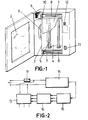
- Figure 1 shows a continuous slide projector of the type described, which fundamentally consists of a slide, projector, screen and a carriage to feed slides in continuously.
- the slide strip is a continuous band -1- with the printed images which are to be shown on the successive step forward of the transparent strip.
- the projector set consists of a mirror -2-, side walls -3- and a light box, which has a reflective screen at the rear -4-, a source of light -5- which in the example is formed by two florescent tubes, and the electronic starter -6- for the light tubes.
- the drive mechanism for the images consists of a frame consisting of a body -7-, two spools -8-, one at each end of the frame, which roll the transparent film -1-, each one at one of its ends, two motor reducers -9-, one for each spool; two rollers to support the transparent strip and a set of side rollers -10- to guide the strip; and an electronic control set which will be described hereunder, and the user may start and stop the projector using switch -11-, as well as by manual control of the images using selector -12-.
- Figure 2 is a block diagram of the electronic set which controls movement of the strip and exhibition time, lights switching on and off, and in order to do so it has an exciter -13-linked to the motor and light system and a control unit for the power system -14-, linked through a logical control unit -15- to the aforementioned exciter -13- through some interface circuits -16-, and it also has a set of the safety and protection devices required -17-.
Abstract
Continuous exposure apparatus for transparencies, characterized in that it is comprised of a projection assembly, in a one-piece configuration, housing the projection screen as a mirror wherein the user may visualize himself or herself by activation of a lighting element arranged above the screen ; the main exposure function of the apparatus is performed by a projector which is housed inside the body of the assembly, and a set of transparencies facing the projector are arranged in a transmission system actuated by an electric motor so that the transparencies are moved to a position facing the light beam irradiated by the projector, thereby re- producting the transparencies on the assembly front part acting as screen.
Description
- The object of this Invention Patent is a continuous slide projector which has considerable advantages and innovations compared with different projectors used for the same or similar purposes up to present.
- More specifically, the invention conceived is a projector set, with a screen which is a mirror the user may look at himself in.
- At present, and with reference to the state of present techniques, it is worth mentioning the existence of slide projectors which consist of a projector and a screen that is independent of the former, on which the slides are projected.
- There are various disadvantages to these types of projectors, among which there is partial or total interruption of the slide when someone or something intercepts the ray of light emitted by the projector toward the screen, or the unaesthetic appearance of the screen when not in use.
- In order to avoid such disadvantages, a continuous slide projector has been conceived, the object of this patent, which in a preferential functioning mode, without this being limiting, works through a parallel base housing, the front side of which has a screen that acts as a screen for projection, as well as being a mirror in which the user may look at himself.
- At the front of the projector, located immediately above the screen, there is an illumination set, equipped with the corresponding lamp, which is duly covered. Once this lighting set is activated, it allows the front surface of the screen to act as a mirror, which the user may see himself in.
- Likewise, there is a projection set placed inside the housing, which may be of the incandescent lamp type, properly placed before a succession of slides laid out on a carriage that places them in the ray of light given off by the projector light, so they are projected on the screen included in the set. Said movement may be driven by an electric motor built into the device the projection is to be housed in.
- Likewise, the projector housing shall bear several control buttons to independently activate the set in mirror or slide projector mode.
- In order to achieve a more detailed description of the invention, this shall refer to the attached figures in which, for example, without this being limiting at all, the preferred form of construction has been described.
- In the drawings:
- Figure 1 represents a partial section perspective view of the projector, showing its main components.
- Figure 2, shows the block diagram of the electronic set which controls the system.
- Figure 1 shows a continuous slide projector of the type described, which fundamentally consists of a slide, projector, screen and a carriage to feed slides in continuously.
- The slide strip is a continuous band -1- with the printed images which are to be shown on the successive step forward of the transparent strip.
- The projector set consists of a mirror -2-, side walls -3- and a light box, which has a reflective screen at the rear -4-, a source of light -5- which in the example is formed by two florescent tubes, and the electronic starter -6- for the light tubes.
- The drive mechanism for the images consists of a frame consisting of a body -7-, two spools -8-, one at each end of the frame, which roll the transparent film -1-, each one at one of its ends, two motor reducers -9-, one for each spool; two rollers to support the transparent strip and a set of side rollers -10- to guide the strip; and an electronic control set which will be described hereunder, and the user may start and stop the projector using switch -11-, as well as by manual control of the images using selector -12-.
- Figure 2 is a block diagram of the electronic set which controls movement of the strip and exhibition time, lights switching on and off, and in order to do so it has an exciter -13-linked to the motor and light system and a control unit for the power system -14-, linked through a logical control unit -15- to the aforementioned exciter -13- through some interface circuits -16-, and it also has a set of the safety and protection devices required -17-.
Claims (5)
1. Continuous slide projector, characterised by consisting of one sole body of a projection set that allows its screen to be used as a mirror in which one may look at oneself when a light above the screen is lit. Because, in order to work in its main mode as a back-projector, it houses a projector mechanism facing a film strip which is automatically driven forward by a mechanism into the ray of light emitted by the projector, so the images are reproduced on the front of the housing, which acts as a screen, and in order for it to work independently of the set, it has various separate switches for the mirror and projector lights.
2. Continuous slide projector, according to the preceding claim, characterised by showing the slides on a screen formed by a mirror, so the user located in front of it may look at himself at will, by interrupting the projections, as well as during the time between successive projections.
3. Continuous slide projector, according to claims 1 and 2, characterised by continuously running images which are preferentially located on a transparent strip and may be viewed in different viewing modes, previously chosen by the user to allow manual observation (one by one), or continuous viewing by automatic projection of the themes chosen, or series of these, or by predetermined or selected sequences.
4. Continuous slide projector, according to claims 1 to 3, characterised by including a motorised double drive system for the film strip, controlled by an electronic set.
5. Continuous slide projector, as in claims 1 to 4, characterised because the aforementioned electronic control set (is established by means of) an exciter linked to the motor and light system, and a control unit for the power system which is linked to the aforementioned exciter through a logical control unit by means of some interface circuits, and said control set runs the film strip movement and the exhibition times of the images, as well as switching on and off the lights.
Applications Claiming Priority (3)
| Application Number | Priority Date | Filing Date | Title |
|---|---|---|---|
| ES9200800 | 1992-04-13 | ||
| ES09200800A ES2043541B1 (en) | 1992-04-13 | 1992-04-13 | CONTINUOUS TRANSPARENCY EXHIBITOR. |
| PCT/ES1993/000027 WO1993021622A1 (en) | 1992-04-13 | 1993-04-12 | Continuous exposure apparatus for transparencies |
Publications (1)
| Publication Number | Publication Date |
|---|---|
| EP0596056A1 true EP0596056A1 (en) | 1994-05-11 |
Family
ID=8276732
Family Applications (1)
| Application Number | Title | Priority Date | Filing Date |
|---|---|---|---|
| EP93907876A Withdrawn EP0596056A1 (en) | 1992-04-13 | 1993-04-12 | Continuous exposure apparatus for transparencies |
Country Status (6)
| Country | Link |
|---|---|
| US (1) | US5515120A (en) |
| EP (1) | EP0596056A1 (en) |
| AU (1) | AU3891693A (en) |
| BR (1) | BR9305480A (en) |
| ES (1) | ES2043541B1 (en) |
| WO (1) | WO1993021622A1 (en) |
Cited By (1)
| Publication number | Priority date | Publication date | Assignee | Title |
|---|---|---|---|---|
| WO1995023401A1 (en) * | 1994-02-25 | 1995-08-31 | Ingo Niggemeyer | Advertising mirror |
Families Citing this family (1)
| Publication number | Priority date | Publication date | Assignee | Title |
|---|---|---|---|---|
| DE29905642U1 (en) * | 1999-03-26 | 1999-07-01 | Fang Chen Tai | Projection ornament |
Family Cites Families (10)
| Publication number | Priority date | Publication date | Assignee | Title |
|---|---|---|---|---|
| US1452797A (en) * | 1921-07-26 | 1923-04-24 | William H C Dudley | Stereopticon device |
| FR555025A (en) * | 1922-02-13 | 1923-06-21 | Improvements made to devices intended to display images, drawings, advertisements, etc. | |
| CH111672A (en) * | 1924-05-28 | 1925-09-16 | Villani Albino | Light board with changing effects. |
| US4351591A (en) * | 1979-12-03 | 1982-09-28 | Logicon, Inc. | Merchandising terminal |
| US4390257A (en) * | 1981-02-23 | 1983-06-28 | Senscom Corporation | Hand held viewer for various size films |
| DE3242409A1 (en) * | 1982-11-16 | 1984-05-17 | Tonstudio Frankfurt GmbH & Co KG, 6000 Frankfurt | Optical advertising device having a light-transmitting mirror |
| IT1192065B (en) * | 1986-01-07 | 1988-03-31 | Zanetti Franco Epc System | DEVICE FOR DISPLAYING ADVERTISING MESSAGES |
| US4942411A (en) * | 1988-06-27 | 1990-07-17 | Polston Steve A | Automatic overlay feed apparatus for an overhead projector |
| DE8900395U1 (en) * | 1989-01-14 | 1989-06-15 | Marjanovic, Marco, 2000 Hamburg, De | |
| US5223868A (en) * | 1991-05-16 | 1993-06-29 | Coiner Ii George | Dashboard mounted microfiche reader |
-
1992
- 1992-04-13 ES ES09200800A patent/ES2043541B1/en not_active Expired - Fee Related
-
1993
- 1993-04-12 EP EP93907876A patent/EP0596056A1/en not_active Withdrawn
- 1993-04-12 BR BR9305480A patent/BR9305480A/en unknown
- 1993-04-12 US US08/162,089 patent/US5515120A/en not_active Expired - Fee Related
- 1993-04-12 WO PCT/ES1993/000027 patent/WO1993021622A1/en not_active Application Discontinuation
- 1993-04-12 AU AU38916/93A patent/AU3891693A/en not_active Abandoned
Non-Patent Citations (1)
| Title |
|---|
| See references of WO9321622A1 * |
Cited By (1)
| Publication number | Priority date | Publication date | Assignee | Title |
|---|---|---|---|---|
| WO1995023401A1 (en) * | 1994-02-25 | 1995-08-31 | Ingo Niggemeyer | Advertising mirror |
Also Published As
| Publication number | Publication date |
|---|---|
| WO1993021622A1 (en) | 1993-10-28 |
| ES2043541R (en) | 1994-06-16 |
| ES2043541B1 (en) | 1995-02-16 |
| ES2043541A2 (en) | 1993-12-16 |
| BR9305480A (en) | 1994-12-13 |
| AU3891693A (en) | 1993-11-18 |
| US5515120A (en) | 1996-05-07 |
Similar Documents
| Publication | Publication Date | Title |
|---|---|---|
| US7470044B2 (en) | Light diffusion device | |
| WO2003100315B1 (en) | Illuminating device, and photographing device and projector device using this illuminating device | |
| ES2118642T3 (en) | PROJECTOR WITH LIGHT SPRINGS OF MULTIPLE LAMPS. | |
| JPS5750702A (en) | Multiplex effect light source used as projector for photograph, movie, television or optical panel or illuminator | |
| US2291931A (en) | Prompting apparatus | |
| EP0596056A1 (en) | Continuous exposure apparatus for transparencies | |
| US5752097A (en) | Apparatus for supporting a camera to face a subject to be photographed and for illuminating the subject | |
| US4896175A (en) | Photography booth and method | |
| JP2875959B2 (en) | Guidance display device | |
| WO2004008742A3 (en) | A light source triggering device | |
| US3888462A (en) | Photographic projector with fader device | |
| US2343046A (en) | Automatic motor starting changeover device for use with two or more motion-picture projectors | |
| JP2894993B2 (en) | Lighting equipment | |
| KR100218861B1 (en) | Controller for photographic lighting | |
| US3733118A (en) | Film training projector | |
| US3259386A (en) | Method of and system for staging productions | |
| US1483025A (en) | Projecting machine | |
| US1631593A (en) | Photographic apparatus | |
| US3147665A (en) | Photocopy machine | |
| SE8900966L (en) | DEVICE FOR PICTURE VIEW | |
| KR100257994B1 (en) | Lighting blue filter apparatus | |
| US3769884A (en) | Photolettering apparatus | |
| JP2946096B2 (en) | Photo printing equipment | |
| JPS6291927A (en) | Overhead projector | |
| US2201885A (en) | Photographic printing machine |
Legal Events
| Date | Code | Title | Description |
|---|---|---|---|
| PUAI | Public reference made under article 153(3) epc to a published international application that has entered the european phase |
Free format text: ORIGINAL CODE: 0009012 |
|
| AK | Designated contracting states |
Kind code of ref document: A1 Designated state(s): AT BE CH DE DK FR GB GR IE IT LI LU MC NL PT SE |
|
| 17P | Request for examination filed |
Effective date: 19940430 |
|
| 17Q | First examination report despatched |
Effective date: 19950922 |
|
| STAA | Information on the status of an ep patent application or granted ep patent |
Free format text: STATUS: THE APPLICATION IS DEEMED TO BE WITHDRAWN |
|
| 18D | Application deemed to be withdrawn |
Effective date: 19960203 |