EP0596041B1 - Method and installation for treating mercury-contaminated soil - Google Patents
Method and installation for treating mercury-contaminated soil Download PDFInfo
- Publication number
- EP0596041B1 EP0596041B1 EP19920918337 EP92918337A EP0596041B1 EP 0596041 B1 EP0596041 B1 EP 0596041B1 EP 19920918337 EP19920918337 EP 19920918337 EP 92918337 A EP92918337 A EP 92918337A EP 0596041 B1 EP0596041 B1 EP 0596041B1
- Authority
- EP
- European Patent Office
- Prior art keywords
- mercury
- sieve
- shaking table
- cyclone
- fed
- Prior art date
- Legal status (The legal status is an assumption and is not a legal conclusion. Google has not performed a legal analysis and makes no representation as to the accuracy of the status listed.)
- Expired - Lifetime
Links
Images


Classifications
-
- B—PERFORMING OPERATIONS; TRANSPORTING
- B03—SEPARATION OF SOLID MATERIALS USING LIQUIDS OR USING PNEUMATIC TABLES OR JIGS; MAGNETIC OR ELECTROSTATIC SEPARATION OF SOLID MATERIALS FROM SOLID MATERIALS OR FLUIDS; SEPARATION BY HIGH-VOLTAGE ELECTRIC FIELDS
- B03B—SEPARATING SOLID MATERIALS USING LIQUIDS OR USING PNEUMATIC TABLES OR JIGS
- B03B9/00—General arrangement of separating plant, e.g. flow sheets
- B03B9/06—General arrangement of separating plant, e.g. flow sheets specially adapted for refuse
- B03B9/061—General arrangement of separating plant, e.g. flow sheets specially adapted for refuse the refuse being industrial
- B03B9/062—General arrangement of separating plant, e.g. flow sheets specially adapted for refuse the refuse being industrial the refuse being glass
-
- B—PERFORMING OPERATIONS; TRANSPORTING
- B03—SEPARATION OF SOLID MATERIALS USING LIQUIDS OR USING PNEUMATIC TABLES OR JIGS; MAGNETIC OR ELECTROSTATIC SEPARATION OF SOLID MATERIALS FROM SOLID MATERIALS OR FLUIDS; SEPARATION BY HIGH-VOLTAGE ELECTRIC FIELDS
- B03B—SEPARATING SOLID MATERIALS USING LIQUIDS OR USING PNEUMATIC TABLES OR JIGS
- B03B5/00—Washing granular, powdered or lumpy materials; Wet separating
- B03B5/02—Washing granular, powdered or lumpy materials; Wet separating using shaken, pulsated or stirred beds as the principal means of separation
- B03B5/04—Washing granular, powdered or lumpy materials; Wet separating using shaken, pulsated or stirred beds as the principal means of separation on shaking tables
-
- B—PERFORMING OPERATIONS; TRANSPORTING
- B09—DISPOSAL OF SOLID WASTE; RECLAMATION OF CONTAMINATED SOIL
- B09C—RECLAMATION OF CONTAMINATED SOIL
- B09C1/00—Reclamation of contaminated soil
- B09C1/02—Extraction using liquids, e.g. washing, leaching, flotation
-
- Y—GENERAL TAGGING OF NEW TECHNOLOGICAL DEVELOPMENTS; GENERAL TAGGING OF CROSS-SECTIONAL TECHNOLOGIES SPANNING OVER SEVERAL SECTIONS OF THE IPC; TECHNICAL SUBJECTS COVERED BY FORMER USPC CROSS-REFERENCE ART COLLECTIONS [XRACs] AND DIGESTS
- Y02—TECHNOLOGIES OR APPLICATIONS FOR MITIGATION OR ADAPTATION AGAINST CLIMATE CHANGE
- Y02W—CLIMATE CHANGE MITIGATION TECHNOLOGIES RELATED TO WASTEWATER TREATMENT OR WASTE MANAGEMENT
- Y02W30/00—Technologies for solid waste management
- Y02W30/50—Reuse, recycling or recovery technologies
- Y02W30/52—Mechanical processing of waste for the recovery of materials, e.g. crushing, shredding, separation or disassembly
-
- Y—GENERAL TAGGING OF NEW TECHNOLOGICAL DEVELOPMENTS; GENERAL TAGGING OF CROSS-SECTIONAL TECHNOLOGIES SPANNING OVER SEVERAL SECTIONS OF THE IPC; TECHNICAL SUBJECTS COVERED BY FORMER USPC CROSS-REFERENCE ART COLLECTIONS [XRACs] AND DIGESTS
- Y02—TECHNOLOGIES OR APPLICATIONS FOR MITIGATION OR ADAPTATION AGAINST CLIMATE CHANGE
- Y02W—CLIMATE CHANGE MITIGATION TECHNOLOGIES RELATED TO WASTEWATER TREATMENT OR WASTE MANAGEMENT
- Y02W30/00—Technologies for solid waste management
- Y02W30/50—Reuse, recycling or recovery technologies
- Y02W30/60—Glass recycling
Definitions
- the invention relates in the first instance to a method for reducing the mercury content of mercury-contaminated soil, comprising: feeding the mercury-contaminated soil to a sieve, feeding the relatively fine material which has passed through the sieve together with water, a degreasing agent and a surface tension-lowering agent, to a shaking table of the Wilfley type, which is provided on its upper surface with ridges, the length of which increases from a first side of the table to a second side of the table, which second side is opposite said first side, shaking the table parallel to said ridges, the mercury concentrate separated off being removed in the vicinity of a point essentially diagonally opposite the pulp feed and the treated material being collected at the said second side.
- Mercury is released in the production of natural gas, in particular in the period when the gas produced is cooled from about 300°C to about 60°. It is true that this mercury is collected at the production well, but in practice it is found that spilling occurs. The spilt mercury penetrates into the soil, which gives rise to serious contamination. Mercury, which is able to contaminate the soil, can also be released during the production of salt and in certain electrolysis processes. Mercury-contaminated soil is also encountered in the vicinity of former mirror factories. Mercury-contaminated glass arises when used or rejected fluorescent tubes are collected and processed.
- the soil is classified in the wet state on a shaking sieve.
- the coarse material goes to a waste tip in the material which has passed through the sieve is passed, after it has been freed from sludge and the bulk of the water in a flow classifier, in the thickened state into a mercury trap in order to separate off the large mercury droplets and to feed these to a vessel.
- the overflow from this mercury trap is passed successively over two shaking tables provided with ridges, the mercury-containing concentrate from said tables being discharged into the said mercury vessel.
- the treated material is fed to a collection vessel.
- a moistening agent is added to the water which is sprayed onto the shaking sieve.
- the aim of this known method is to produce a high mercury content in the enriched concentrate, and the method is not suitable for reducing the mercury content in the soil for environmental reasons to less than 10 mg of mercury per kg of solids. Moreover, recycling of liquid and treatment of return liquid and sludge removal from the latter, does not take place.
- the aim of the invention is to provide an efficient, simple and environmentally friendly method for the removal of mercury from the soil or other granular material, the treated product containing less than 10 mg of mercury per kg of solids.
- the method mentioned in the preamble is characterised in that to reduce the mercury content of the contaminated soil from a maximum of about 300 mg of mercury per kg of solids to less than 10 mg of mercury per kg of solids, the feeding of the soil to said sieve takes place in the essentially dry state, and the discharge end of the connecting channel between sieve and shaking table being below the liquid level, in that the material collected in a gutter at the second side of the shaking table is fed via a pump to at least one cyclone which is separating-off the sludge ( ⁇ 30-40 ⁇ m) from the pulp, in that the pulp in said cyclone is dewatered and the overflow material from the cyclone, mixed with a flocculant, is fed to a thickener device in order to separate off suspended sludge particles smaller than 30 to 40 ⁇ m and the water freed from suspended sludge is recycled to said sieve and/or shaking table.
- An essential feature of the invention is that the contaminated material is transported in the essential dry state, without a pump, to a position above the shaking table.
- some of the mercury would collect in the bottom of the pump.
- the addition of a decreasing agent and a surface tensioning - lowering agent are also important for the yield of the process. Without the additions, some of the mercury globules would become floatable and move over the ridges with relatively lightweight soil grains. Recycling of the overflow from the cyclone is desirable in order to restrict the loss of liquid.
- a liquid (overflow from the cyclone) to be recycled to the sieve and/or shaking table must be freed from suspended sludge particles in order to be able to achieve the desired degree of purification. Fine sludge particles are also removed by this cyclone, with the overflow.
- the contaminated soil will in general also contain coarse particles and therefore it is necessary to separate these off before treatment on the shaking table. It is for this reasons that the contaminated material is subjected to a screening process before it is introduced on the shaking table, only the coarse material retained on a sieve of mesh width 2mm being discharged separately.
- the water freed from the sludge will be passed to a sand filter and/or active carbon filter.
- the aim of the requirement, in the present method, that the discharge end of the connecting channel between sieve and shaking table must be below the liquid level is to immerse the soil material in the liquid on the Wilfley table.
- the removal of suspended sludge particles from the soil and from the return liquid is necessary in order to achieve the desired degree of purity (less than 10 mm of mercury per kg of solids).
- the invention also relates to an installation for carrying out the abovementioned method.
- DDR patent 124500 discloses such an installation having a shaking table of the Wilfley type which is provided on its upper surface with parallel ridges of a length which increases from a first table side to a second table side opposite said first side, a vibratory sieve with a discharge for sieved material which opens above a feed tray in the shaking table in the vicinity of one end of said first side of said table, a transport mechanism to feed soil to the vibratory sieve, a discharge, for mercury separated off, diagonally opposite the material fed to the shaking table.
- the transport mechanism to feed the contaminated soil to the vibratory sieve does not have a pump and is suitable to transport the material in the essentially dry state
- the installation further comprises at least one cyclone in order to dewater the treated material, and a line in order to feed liquid separated off in the cyclone to a thickener for separating small sludge particles, as well as a line in order to recycle liquid freed from sludge to said sieve and/or shaking table.
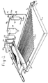
- Figure 1 shows a perspective view of part of the installation which is used for the method according to the invention.
- Figure 2 shows a side view of the complete installation.
- Figure 3 shows a flow sheet
- the installation shown in Figures 1 and 2 for removal of mercury from the contaminated soil comprises a shaking table 1 of the Wilfley type.
- This consists of a flat surface, usually covered with linoleum or plastic or rubber, and ridges 2 which are made on said covering and extend parallel to the longitudinal direction of the table.
- the shaking table can be made to shake in a direction parallel to the corrugations by means of an eccentric mechanism 6 driven by a motor 6a.
- a vibratory sieve 7, provided with vibrating motors 8, is positioned above the shaking table.
- the discharge end of a feed conveyor 9 is located over the vibratory sieve.
- the installation also comprises a pump tank 10, a pump 11, at least one cyclone 12 and a buffer tank 13.
- An overflow branch 15 from the tank 13 is connected to the gutter via a line 16, whilst a discharge at the bottom of the tank is connected via a line 17 containing the valve 17a to the pump tank 10.
- Branch 18, provided with a valve 18a, from the up flow line 14 is connected to the tangential inlet of at least one cyclone 12 which is able partially to dewater the treated material fed into it.
- the overflow line 19 from the cyclone opens into a thickener 12, into which a flocculant (for example FeCl) can be fed via a line 22.
- the thickener separates off suspended sludge particles ( ⁇ 30 to 40 ⁇ m) and has a discharge 21 for the sludge material separated off.
- the overflow line of the thickener opens into a sand filter 23, the discharge of which, in its turn, opens into an active carbon filter 24, the discharge of which leads to a buffer tank 25.
- the sand filter and the active carbon filter serve to remove mercury from the liquid freed from sludge.
- Lines 26 and 27 lead from the buffer tank 25 to the sieve 7 and the table 1.
- the underflow from the cyclone is fed via discharge 19a to a dewatering sieve and further dewatered to give the treated product.
- the installation functions as follows: Dry granular material which is contaminated with mercury is fed via the loading conveyor 9, a conveyor belt or screw, from a bunker, which is not shown, to the vibratory sieve 7. Water is supplied to this sieve in an amount such that the mixture contains about 25% solids.
- the mesh size of the sieve is about 2 mm.
- the coarse material (for example about 5% of the original dry material) is discharged separately.
- the pulp material which has passed through the sieve flows onto the feed tray 3 of the shaking table 1.
- a degreasing agent and a surface-tension-reducing agent are added to this pulp stream. Additional water is fed to the table in order to keep the mixture fluid.
- the discharge end of the connecting channel 7a between the sieve 7 and the shaking table 1 is located below the liquid level so that the particulate material is immersed in the liquid on the table, and floating of particles is counteracted.
- Shaking of the table proceeds not in accordance with a sinusoidal curve but in accordance with a curve in which the speed of movement is increased to a maximum in the outward stroke and a return stroke starts with a maximum speed and this speed gradually decreases.
- the relatively heavy mercury particles which are in contact with the table acquire an acceleration which is virtually equal to that of the table. If the heavy mercury particles are at their maximum speed and the table is drawn back at the start of the return stroke, said heavy mercury particles will slightly overshoot and be moved in the longitudinal direction of the ridges.
- the relatively lightweight grains lying on the heavy particles are exposed to a stronger water flow than are the heavy particles and will be carried along by the water flow on the table, especially in the transverse direction of the table. The result is that the mercury collects in the gutter 5 and the treated material in the gutter 4. To intensify the separation effect, the height of the ridges could decrease in their longitudinal direction.
- the pulp material which has collected in the gutter 4 passes into the pump tank 10 and is fed by the pump 11 via the lines 14 and 18 tangentially into the cyclone 12, freed from sludge ( ⁇ 30 - 40 ⁇ m) and about 65% dewatered.
- the water from the overflow of the cyclone is discharged via line 19 and is successively subjected to separation of sludge particles smaller than 30 to 40 ⁇ m in the thickener 20, and separation of mercury in the filters 23 and 24.
- the largely sludge-free and mercury-free water is recycled via the process water tank 25 and the lines 26 and 27 to the sieve 7 and the table 1.
- the cyclone 12 also has a discharge 19a for the underflow.
- the underflow is fed to a dewatering sieve, which is not shown, and further dewatered.
- the water issuing from the dewatering sieve is pumped to the buffer tank 13 in order to maintain the level in the pump tank 10, via the line 17.
- Figure 3 shows the successive steps of the process according to the invention schematically in a flow sheet.
- the degreasing agent and the surface-tension-reducing agent added are important for the yield of the method.
- the degreasing agent can be a non-basic cleaner (for example CD45) which has a good moistening effect on contaminated surfaces.
- the dosage is, for example, 50 ppm.
- the surface-tension-lowering agent used can be a de-emulsifier for oil/water emulsions (for example CD659).
- the dosage is, for example, 200 ppm.
- the mercury content of the soil can be reduced to less than 10 mg of mercury per kg of solids and the treated liquid can, to a large extent, be re-used.
Landscapes
- Life Sciences & Earth Sciences (AREA)
- Soil Sciences (AREA)
- Engineering & Computer Science (AREA)
- Environmental & Geological Engineering (AREA)
- Processing Of Solid Wastes (AREA)
- Separation Of Solids By Using Liquids Or Pneumatic Power (AREA)
- Treating Waste Gases (AREA)
Abstract
Description
- The invention relates in the first instance to a method for reducing the mercury content of mercury-contaminated soil, comprising:
feeding the mercury-contaminated soil to a sieve,
feeding the relatively fine material which has passed through the sieve together with water, a degreasing agent and a surface tension-lowering agent, to a shaking table of the Wilfley type, which is provided on its upper surface with ridges, the length of which increases from a first side of the table to a second side of the table, which second side is opposite said first side,
shaking the table parallel to said ridges, the mercury concentrate separated off being removed in the vicinity of a point essentially diagonally opposite the pulp feed and the treated material being collected at the said second side. - A method of this kind is disclosed in DDR patent 124500.
- Mercury is released in the production of natural gas, in particular in the period when the gas produced is cooled from about 300°C to about 60°. It is true that this mercury is collected at the production well, but in practice it is found that spilling occurs. The spilt mercury penetrates into the soil, which gives rise to serious contamination. Mercury, which is able to contaminate the soil, can also be released during the production of salt and in certain electrolysis processes. Mercury-contaminated soil is also encountered in the vicinity of former mirror factories. Mercury-contaminated glass arises when used or rejected fluorescent tubes are collected and processed.
- An extraction method is not unusual for treating mercury-contaminated soil. In this method the mercury is first brought into solution, the solution is discharged and the mercury is removed from the liquid. Evaporation in order to remove mercury from the soil is also a possibility. Both methods are laborious and environmentally unfriendly. Removal of mercury by evaporation is also dangerous for bystanders.
- According to the above mentioned DDR patent 124500 the soil is classified in the wet state on a shaking sieve. The coarse material goes to a waste tip in the material which has passed through the sieve is passed, after it has been freed from sludge and the bulk of the water in a flow classifier, in the thickened state into a mercury trap in order to separate off the large mercury droplets and to feed these to a vessel. The overflow from this mercury trap is passed successively over two shaking tables provided with ridges, the mercury-containing concentrate from said tables being discharged into the said mercury vessel. The treated material is fed to a collection vessel. In order to counteract the floating of mercury drops, a moistening agent is added to the water which is sprayed onto the shaking sieve. The aim of this known method is to produce a high mercury content in the enriched concentrate, and the method is not suitable for reducing the mercury content in the soil for environmental reasons to less than 10 mg of mercury per kg of solids. Moreover, recycling of liquid and treatment of return liquid and sludge removal from the latter, does not take place.
- The aim of the invention is to provide an efficient, simple and environmentally friendly method for the removal of mercury from the soil or other granular material, the treated product containing less than 10 mg of mercury per kg of solids.
- To this end the method mentioned in the preamble is characterised in that to reduce the mercury content of the contaminated soil from a maximum of about 300 mg of mercury per kg of solids to less than 10 mg of mercury per kg of solids, the feeding of the soil to said sieve takes place in the essentially dry state, and the discharge end of the connecting channel between sieve and shaking table being below the liquid level, in that the material collected in a gutter at the second side of the shaking table is fed via a pump to at least one cyclone which is separating-off the sludge (<30-40 µm) from the pulp, in that the pulp in said cyclone is dewatered and the overflow material from the cyclone, mixed with a flocculant, is fed to a thickener device in order to separate off suspended sludge particles smaller than 30 to 40 µm and the water freed from suspended sludge is recycled to said sieve and/or shaking table.
- An essential feature of the invention is that the contaminated material is transported in the essential dry state, without a pump, to a position above the shaking table. In the case of the transport of a wet feed with the aid of a pump, some of the mercury would collect in the bottom of the pump. The addition of a decreasing agent and a surface tensioning - lowering agent are also important for the yield of the process. Without the additions, some of the mercury globules would become floatable and move over the ridges with relatively lightweight soil grains. Recycling of the overflow from the cyclone is desirable in order to restrict the loss of liquid. A liquid (overflow from the cyclone) to be recycled to the sieve and/or shaking table must be freed from suspended sludge particles in order to be able to achieve the desired degree of purification. Fine sludge particles are also removed by this cyclone, with the overflow. The contaminated soil will in general also contain coarse particles and therefore it is necessary to separate these off before treatment on the shaking table. It is for this reasons that the contaminated material is subjected to a screening process before it is introduced on the shaking table, only the coarse material retained on a sieve of mesh width 2mm being discharged separately.
- To remove the bulk of the residual mercury content in the water to be recycled to the sieve and/or shaking table, the water freed from the sludge will be passed to a sand filter and/or active carbon filter.
- The aim of the requirement, in the present method, that the discharge end of the connecting channel between sieve and shaking table must be below the liquid level is to immerse the soil material in the liquid on the Wilfley table. The removal of suspended sludge particles from the soil and from the return liquid is necessary in order to achieve the desired degree of purity (less than 10 mm of mercury per kg of solids).
- The invention also relates to an installation for carrying out the abovementioned method. DDR patent 124500 discloses such an installation having a shaking table of the Wilfley type which is provided on its upper surface with parallel ridges of a length which increases from a first table side to a second table side opposite said first side, a vibratory sieve with a discharge for sieved material which opens above a feed tray in the shaking table in the vicinity of one end of said first side of said table, a transport mechanism to feed soil to the vibratory sieve, a discharge, for mercury separated off, diagonally opposite the material fed to the shaking table.
- In order to be able to carry out the abovementioned method the transport mechanism to feed the contaminated soil to the vibratory sieve does not have a pump and is suitable to transport the material in the essentially dry state, whereas the installation further comprises at least one cyclone in order to dewater the treated material, and a line in order to feed liquid separated off in the cyclone to a thickener for separating small sludge particles, as well as a line in order to recycle liquid freed from sludge to said sieve and/or shaking table.
- The invention will now be illustrated in more detail with the aid of the Figures.
- Figure 1 shows a perspective view of part of the installation which is used for the method according to the invention.
- Figure 2 shows a side view of the complete installation.
- Figure 3 shows a flow sheet.
- The installation shown in Figures 1 and 2 for removal of mercury from the contaminated soil comprises a shaking table 1 of the Wilfley type. This consists of a flat surface, usually covered with linoleum or plastic or rubber, and ridges 2 which are made on said covering and extend parallel to the longitudinal direction of the table.
- At one corner of the table there is a
feed tray 3, the length of the ridges increasing from the longitudinal edge of the table bordering the feed tray in the direction of the other longitudinal edge. A gutter 4 is made in the other longitudinal edge and there is adrain 5 at the corner diametrically opposite said feed corner. The shaking table can be made to shake in a direction parallel to the corrugations by means of aneccentric mechanism 6 driven by a motor 6a. - A vibratory sieve 7, provided with vibrating motors 8, is positioned above the shaking table. The discharge end of a
feed conveyor 9 is located over the vibratory sieve. - The installation also comprises a
pump tank 10, apump 11, at least onecyclone 12 and abuffer tank 13. Anoverflow branch 15 from thetank 13 is connected to the gutter via aline 16, whilst a discharge at the bottom of the tank is connected via aline 17 containing thevalve 17a to thepump tank 10. -
Branch 18, provided with avalve 18a, from the upflow line 14 is connected to the tangential inlet of at least onecyclone 12 which is able partially to dewater the treated material fed into it. Theoverflow line 19 from the cyclone opens into athickener 12, into which a flocculant (for example FeCl) can be fed via a line 22. The thickener separates off suspended sludge particles (<30 to 40 µm) and has adischarge 21 for the sludge material separated off. The overflow line of the thickener opens into asand filter 23, the discharge of which, in its turn, opens into anactive carbon filter 24, the discharge of which leads to abuffer tank 25. The sand filter and the active carbon filter serve to remove mercury from the liquid freed from sludge.Lines buffer tank 25 to the sieve 7 and the table 1. The underflow from the cyclone is fed viadischarge 19a to a dewatering sieve and further dewatered to give the treated product. - The installation functions as follows:
Dry granular material which is contaminated with mercury is fed via theloading conveyor 9, a conveyor belt or screw, from a bunker, which is not shown, to the vibratory sieve 7. Water is supplied to this sieve in an amount such that the mixture contains about 25% solids. The mesh size of the sieve is about 2 mm. The coarse material (for example about 5% of the original dry material) is discharged separately. - The pulp material which has passed through the sieve flows onto the
feed tray 3 of the shaking table 1. A degreasing agent and a surface-tension-reducing agent are added to this pulp stream. Additional water is fed to the table in order to keep the mixture fluid. The discharge end of the connectingchannel 7a between the sieve 7 and the shaking table 1 is located below the liquid level so that the particulate material is immersed in the liquid on the table, and floating of particles is counteracted. - Shaking of the table proceeds not in accordance with a sinusoidal curve but in accordance with a curve in which the speed of movement is increased to a maximum in the outward stroke and a return stroke starts with a maximum speed and this speed gradually decreases. In the outward stroke, the relatively heavy mercury particles which are in contact with the table acquire an acceleration which is virtually equal to that of the table. If the heavy mercury particles are at their maximum speed and the table is drawn back at the start of the return stroke, said heavy mercury particles will slightly overshoot and be moved in the longitudinal direction of the ridges. The relatively lightweight grains lying on the heavy particles are exposed to a stronger water flow than are the heavy particles and will be carried along by the water flow on the table, especially in the transverse direction of the table. The result is that the mercury collects in the
gutter 5 and the treated material in the gutter 4. To intensify the separation effect, the height of the ridges could decrease in their longitudinal direction. - The pulp material which has collected in the gutter 4 passes into the
pump tank 10 and is fed by thepump 11 via thelines cyclone 12, freed from sludge (<30 - 40 µm) and about 65% dewatered. The water from the overflow of the cyclone is discharged vialine 19 and is successively subjected to separation of sludge particles smaller than 30 to 40 µm in thethickener 20, and separation of mercury in thefilters process water tank 25 and thelines cyclone 12 also has adischarge 19a for the underflow. The underflow is fed to a dewatering sieve, which is not shown, and further dewatered. The water issuing from the dewatering sieve is pumped to thebuffer tank 13 in order to maintain the level in thepump tank 10, via theline 17. - As a result of the dry feeding of the material to the vibratory sieve 7, without the use of pumps, mercury is not able to volatilise and remain behind in a pump or line.
- Figure 3 shows the successive steps of the process according to the invention schematically in a flow sheet.
- This process is suitable for treating sand, clay, peat, sewer sludge, underwater beds, fluorescent tube waste (mercury-containing ground glass containing fluorescent powder), treatment sludge from waste water treatment installations and diverse other waste materials. The degreasing agent and the surface-tension-reducing agent added are important for the yield of the method. The degreasing agent can be a non-basic cleaner (for example CD45) which has a good moistening effect on contaminated surfaces. The dosage is, for example, 50 ppm. The surface-tension-lowering agent used can be a de-emulsifier for oil/water emulsions (for example CD659). The dosage is, for example, 200 ppm. The mercury content of the soil can be reduced to less than 10 mg of mercury per kg of solids and the treated liquid can, to a large extent, be re-used.
Claims (5)
- Method for reducing the mercury content of mercury-contaminated soil, comprising:
feeding the mercury-contaminated soil to a sieve,
feeding the relatively fine material which has passed through the sieve together with water, a degreasing agent and a surface tension-lowering agent, to a shaking table of the Wilfley type, which is provided on its upper surface with ridges, the length of which increases from a first side of the table to a second side of the table, which second side is opposite said first side,
shaking the table parallel to said ridges, the mercury concentrate separated off being removed in the vicinity of a point essentially diagonally opposite the pulp feed and the treated material being collected at the said second side,
characterised in that to reduce the mercury content of the contaminated soil from a maximum of about 300 mg of mercury per kg of solids to less than 10 mg of mercury per kg of solids, the feeding of the soil to said sieve takes place in the essentially dry state, and the discharge end of the connecting channel between sieve and shaking table being below the liquid level, in that the material collected in a gutter at the second side of the shaking table is fed via a pump to at least one cyclone which is separating-off the sludge (<30-40 µm) from the pulp, in that the pulp in said cyclone is dewatered and the overflow material from the cyclone, mixed with a flocculant, is fed to a thickener device in order to separate off suspended sludge particles smaller than 30 to 40 µm and the water freed from suspended sludge is recycled to said sieve and/or shaking table. - Method according to Claim 1, characterised in that, before it is fed to said sieve and/or shaking table, the water freed from suspended sludge is treated in a sand filter and/or active carbon filter to remove mercury.
- Installation for reducing the mercury content of mercury-contaminated soil according to the method of Claim 1, comprising a shaking table of the Wilfley type which is provided on its upper surface with parallel ridges of a length which increases from a first table side to a second table side opposite said first side, a vibratory sieve with a discharge for sieved material which opens above a feed tray in the shaking table in the vicinity of one end of said first side of said table, a transport mechanism to feed soil to the vibratory sieve, a discharge, for mercury separated off, diagonally opposite the material fed to the shaking table, characterised in that the transport mechanism to feed the contaminated soil to the vibratory sieve does not have a pump and is suitable to transport the material in the essentially dry state, in that the installation further comprises at least one cyclone in order to dewater the treated material, and a line in order to feed liquid separated off in the cyclone to a thickener for separating small sludge particles, as well as a line in order to recycle liquid freed from sludge to said sieve and/or shaking table.
- Installation according to Claim 3, characterised in that a sand filter and/or active carbon filter to separate off mercury is incorporated in the line which extends from the thickener to the said sieve and/or shaking table.
- Installation according to Claim 4, characterised by a pump tank and pump installed between the discharge for treated material from the shaking table and the cyclone, a dewatering sieve in order further to dewater material partially dewatered in the cyclone, a buffer tank in order to store liquid originating from the dewatering sieve, and a connection, leading from the buffer tank to the pump tank, in order to maintain the level in the pump tank.
Applications Claiming Priority (3)
| Application Number | Priority Date | Filing Date | Title |
|---|---|---|---|
| NL9101340 | 1991-08-02 | ||
| NL9101340A NL9101340A (en) | 1991-08-02 | 1991-08-02 | METHOD AND APPARATUS FOR REMOVING MERCURY FROM CONTAMINATED MATERIAL |
| PCT/NL1992/000137 WO1993002798A1 (en) | 1991-08-02 | 1992-08-03 | Method and installation for treating mercury-contaminated soil |
Publications (2)
| Publication Number | Publication Date |
|---|---|
| EP0596041A1 EP0596041A1 (en) | 1994-05-11 |
| EP0596041B1 true EP0596041B1 (en) | 1996-07-10 |
Family
ID=19859579
Family Applications (1)
| Application Number | Title | Priority Date | Filing Date |
|---|---|---|---|
| EP19920918337 Expired - Lifetime EP0596041B1 (en) | 1991-08-02 | 1992-08-03 | Method and installation for treating mercury-contaminated soil |
Country Status (4)
| Country | Link |
|---|---|
| EP (1) | EP0596041B1 (en) |
| DE (1) | DE69212159T2 (en) |
| NL (1) | NL9101340A (en) |
| WO (1) | WO1993002798A1 (en) |
Families Citing this family (2)
| Publication number | Priority date | Publication date | Assignee | Title |
|---|---|---|---|---|
| KR101529488B1 (en) * | 2014-07-24 | 2015-06-29 | 주식회사 대일이앤씨 | Table apparatus for sorting heavy metal from contaminated soil and method for sorting contaminated therewith |
| ES2749233T3 (en) * | 2014-11-04 | 2020-03-19 | Veos Nv | Device and method for collecting blood from slaughter animals |
Family Cites Families (7)
| Publication number | Priority date | Publication date | Assignee | Title |
|---|---|---|---|---|
| US1582020A (en) * | 1921-04-20 | 1926-04-20 | Elwin M Hulse | Dewatering attachment for concentrating tables |
| DD124500A1 (en) * | 1975-12-19 | 1986-11-12 | Forsch Aufbereitung Der Adw De | PROCESS FOR THE PREPARATION OF MERCURY-SUSTAINING FERTILITY |
| AU502437B2 (en) * | 1976-05-10 | 1979-07-26 | Fmc Corporation | Slurry separation |
| CH625491A5 (en) * | 1976-12-10 | 1981-09-30 | Lonza Ag | Process for reclaiming mercury from Hg-containing waste waters. |
| SE457149B (en) * | 1987-04-16 | 1988-12-05 | Mrt System Ab | PROCEDURE FOR Separation of mercury-containing waste |
| DE3928427C2 (en) * | 1989-08-28 | 1999-08-12 | Ebara Germany Gmbh | Method and device for cleaning material contaminated with heavy metals, in particular mercury |
| DE3932772A1 (en) * | 1989-09-28 | 1991-04-11 | Marcus Matthias Elektro Ofen | METHOD AND DEVICE FOR THE DISPOSAL OF LAMINATE-BASED MERCURY LAMPS |
-
1991
- 1991-08-02 NL NL9101340A patent/NL9101340A/en not_active Application Discontinuation
-
1992
- 1992-08-03 WO PCT/NL1992/000137 patent/WO1993002798A1/en active IP Right Grant
- 1992-08-03 EP EP19920918337 patent/EP0596041B1/en not_active Expired - Lifetime
- 1992-08-03 DE DE69212159T patent/DE69212159T2/en not_active Expired - Fee Related
Also Published As
| Publication number | Publication date |
|---|---|
| WO1993002798A1 (en) | 1993-02-18 |
| NL9101340A (en) | 1993-03-01 |
| EP0596041A1 (en) | 1994-05-11 |
| DE69212159D1 (en) | 1996-08-14 |
| DE69212159T2 (en) | 1996-11-21 |
Similar Documents
| Publication | Publication Date | Title |
|---|---|---|
| US5236596A (en) | Method and apparatus for dewatering | |
| CN1036444C (en) | FGD performance enhancement by hydroclone | |
| US4255269A (en) | Method and apparatus for adapting the composition of a drilling fluid for use in making a hole in the earth by rotary drilling | |
| US5244492A (en) | Process for recovery of metallic mercury from contaminated mercury-containing soil | |
| KR101729262B1 (en) | Adulteration disposal equipment with wedge bar screen | |
| US4701260A (en) | Device for continuous separation of solid particles from a liquid suspension | |
| GB1568923A (en) | Process for cleaning and dewatering fine coal | |
| CN1127673A (en) | Wet process flue gas desulfurization apparatus | |
| KR101431161B1 (en) | Filtering, dehydrating equipment of sand and impurities | |
| US6156083A (en) | Coal reclamation systems | |
| EP0596041B1 (en) | Method and installation for treating mercury-contaminated soil | |
| EP0094114B1 (en) | Method for treating blast furnace gas and apparatus for carrying out that method | |
| US4244813A (en) | Method of increasing fine coal filtration efficiency | |
| RU2086766C1 (en) | Method for clarification of mine inflow water and for dewatering of sludge | |
| JPH0839097A (en) | Polluted water purifying apparatus | |
| EP0647483A1 (en) | Method and device for the purification of polluted sedimentary material | |
| RU2085743C1 (en) | Method for subsurface clarification of circulating water and dewatering of coal slurry | |
| JP3759811B2 (en) | Sewage / septic tank sludge treatment equipment equipped with the same sand removal device from human waste / septic tank sludge | |
| JP2724442B2 (en) | Screw-type waste mud solid-liquid separator | |
| TWI826319B (en) | Deep cleaning technology for highly concentrated contaminated soil | |
| JP2518996B2 (en) | Suspension separator | |
| JPH08281013A (en) | Separation of suspended living things | |
| JPH08132020A (en) | Treatment of waste water containing oil component | |
| RU2100327C1 (en) | Method and installation for removing inorganic inclusions from household waste | |
| CN108883419B (en) | Method and apparatus for treating ash from a waste incineration plant |
Legal Events
| Date | Code | Title | Description |
|---|---|---|---|
| PUAI | Public reference made under article 153(3) epc to a published international application that has entered the european phase |
Free format text: ORIGINAL CODE: 0009012 |
|
| 17P | Request for examination filed |
Effective date: 19940202 |
|
| AK | Designated contracting states |
Kind code of ref document: A1 Designated state(s): DE NL |
|
| 17Q | First examination report despatched |
Effective date: 19950331 |
|
| GRAG | Despatch of communication of intention to grant |
Free format text: ORIGINAL CODE: EPIDOS AGRA |
|
| GRAH | Despatch of communication of intention to grant a patent |
Free format text: ORIGINAL CODE: EPIDOS IGRA |
|
| GRAH | Despatch of communication of intention to grant a patent |
Free format text: ORIGINAL CODE: EPIDOS IGRA |
|
| GRAA | (expected) grant |
Free format text: ORIGINAL CODE: 0009210 |
|
| AK | Designated contracting states |
Kind code of ref document: B1 Designated state(s): DE NL |
|
| REF | Corresponds to: |
Ref document number: 69212159 Country of ref document: DE Date of ref document: 19960814 |
|
| PLBE | No opposition filed within time limit |
Free format text: ORIGINAL CODE: 0009261 |
|
| STAA | Information on the status of an ep patent application or granted ep patent |
Free format text: STATUS: NO OPPOSITION FILED WITHIN TIME LIMIT |
|
| 26N | No opposition filed | ||
| PGFP | Annual fee paid to national office [announced via postgrant information from national office to epo] |
Ref country code: NL Payment date: 20020830 Year of fee payment: 11 |
|
| PGFP | Annual fee paid to national office [announced via postgrant information from national office to epo] |
Ref country code: DE Payment date: 20020905 Year of fee payment: 11 |
|
| PG25 | Lapsed in a contracting state [announced via postgrant information from national office to epo] |
Ref country code: NL Free format text: LAPSE BECAUSE OF NON-PAYMENT OF DUE FEES Effective date: 20040301 |
|
| PG25 | Lapsed in a contracting state [announced via postgrant information from national office to epo] |
Ref country code: DE Free format text: LAPSE BECAUSE OF NON-PAYMENT OF DUE FEES Effective date: 20040302 |
|
| NLV4 | Nl: lapsed or anulled due to non-payment of the annual fee |
Effective date: 20040301 |