EP0595977B1 - Control system for operating the drive assembly of a ship - Google Patents
Control system for operating the drive assembly of a ship Download PDFInfo
- Publication number
- EP0595977B1 EP0595977B1 EP92916358A EP92916358A EP0595977B1 EP 0595977 B1 EP0595977 B1 EP 0595977B1 EP 92916358 A EP92916358 A EP 92916358A EP 92916358 A EP92916358 A EP 92916358A EP 0595977 B1 EP0595977 B1 EP 0595977B1
- Authority
- EP
- European Patent Office
- Prior art keywords
- control
- speed
- clutch
- trolling
- ship
- Prior art date
- Legal status (The legal status is an assumption and is not a legal conclusion. Google has not performed a legal analysis and makes no representation as to the accuracy of the status listed.)
- Expired - Lifetime
Links
Images

Classifications
-
- B—PERFORMING OPERATIONS; TRANSPORTING
- B63—SHIPS OR OTHER WATERBORNE VESSELS; RELATED EQUIPMENT
- B63H—MARINE PROPULSION OR STEERING
- B63H23/00—Transmitting power from propulsion power plant to propulsive elements
- B63H23/22—Transmitting power from propulsion power plant to propulsive elements with non-mechanical gearing
- B63H23/26—Transmitting power from propulsion power plant to propulsive elements with non-mechanical gearing fluid
-
- B—PERFORMING OPERATIONS; TRANSPORTING
- B63—SHIPS OR OTHER WATERBORNE VESSELS; RELATED EQUIPMENT
- B63H—MARINE PROPULSION OR STEERING
- B63H21/00—Use of propulsion power plant or units on vessels
- B63H21/22—Use of propulsion power plant or units on vessels the propulsion power units being controlled from exterior of engine room, e.g. from navigation bridge; Arrangements of order telegraphs
-
- B—PERFORMING OPERATIONS; TRANSPORTING
- B63—SHIPS OR OTHER WATERBORNE VESSELS; RELATED EQUIPMENT
- B63H—MARINE PROPULSION OR STEERING
- B63H23/00—Transmitting power from propulsion power plant to propulsive elements
- B63H23/02—Transmitting power from propulsion power plant to propulsive elements with mechanical gearing
- B63H2023/0291—Trolling gears, i.e. mechanical power transmissions comprising controlled slip clutches, e.g. for low speed propulsion
Definitions
- the invention relates generally to a control system for operating a propulsion system of a ship.
- the drive system has at least one motor that drives a propeller shaft via a gearbox with at least one controllable clutch for forward and reverse travel.
- Control and sensor means are provided in order to be able to vary the engine speed or the degree of slip of the clutch.
- the control system also has control electronics for processing input and output signals in order to maintain the desired operating states of the drive system.
- a mode selection device in which a specific operating mode can be selected.
- the control lever of the control station is assigned a specific function. If the cruise mode is selected, the clutch is closed for forward travel. The control lever is used to vary the engine speed to set a specific cruising speed. If the mode selection device is used to preselect slow travel mode (trolling), the function assigned to the control lever changes. As long as this mode is selected, the motor is operated at a certain, constant speed. The driving speed is varied via the control lever in such a way that the degree of slippage of the clutch of the transmission is more or less is chosen large. The speed of the propeller shaft is thus varied via the degree of slip of the clutch.
- the known control system has control electronics to which an input and output unit, a display unit and control and sensor means are connected.
- direction reversals can be carried out in the troll or travel mode by a corresponding movement of the direction / speed lever.
- the direction reversals are carried out by the control unit in an automatically clocked sequence.
- the motor When changing from travel mode to trolling mode, the motor reduces the speed to a speed selected by a rotary control.
- the engine speed changes towards idling speed, the clutch engages completely, and then the engine speed increases up to the control lever position (DE-A 39 07 841, column 12, lines 16 - 33) .
- a control system for operating the propulsion system of a ship is also known from US Pat. No. 4,099,476, in which an additional auxiliary travel switch is used in addition to a main switch.
- the takeover by one or the other drive switch is error-free and without delay, in that the main drive switch is automatically transferred to a position corresponding to the position of the auxiliary drive switch.
- the present invention is based on the object of influencing the reaction of the ship when reversing in a targeted manner in that the skipper can make use of at least one reversing aid by means of which the time behavior of the ship is changed in a certain way.
- the main aim here is to improve the response times when starting off or during turning maneuvers, especially with low propeller shaft speeds.
- the object underlying the invention is achieved in that in one operating mode (trolling) of the drive system, the clutch is completely closed after switching the direction of travel and the acceleration phase by transmitting a control signal which is the negative adjustment gradient of a control lever resulting from a reduction in the trolling speed is ended to the control electronics by transferring the clutch into the regulated slip mode.
- This solution is a manual reversing aid that is selected by the skipper by pressing a selection button on the control station.
- the clutch is completely closed after switching the direction of travel. This accelerates the ship with a thrust corresponding to the prevailing engine speed. The master may end the acceleration phase if the ship reacts sufficiently.
- the end of the acceleration phase is tied to an adjustment movement of the driving switch (control lever).
- the skipper usually reacts by adjusting the control lever in the sense of "reducing the drive speed”. This reaction is used by ending the acceleration phase by slightly reducing the trolling speed.
- a control signal is transmitted to the control electronics when a negative adjustment gradient of the setpoint generator for the trolling speed is generated.
- the control electronics then convert the clutch to slipping, regulated operation, so that a trolling speed is set automatically.
- the ship's reaction in trolling operation is significantly improved during approach and turning maneuvers.
- the control electronics can interact with the slipping clutch in such a way that the clutch is protected against thermal overload.
- Another solution to the problem is, according to the invention, that in one operating mode (trolling) of the drive system, the clutch is completely closed after switching the direction of travel and the acceleration phase by transmitting a control signal, which indicates that a defined ship speed has been reached, to the control electronics when the clutch is closed is ended by setting the speed of the propeller shaft to a trolling speed. It is advantageous here to derive the control signal for the control electronics from the ship's speed. When a desired ship speed is reached, the control signal is generated or delivered to the control electronics. In a preferred solution, the target ship speed is preselected, for example, using the travel switch. With the help of a suitable measuring element, the ship's speed is determined and the control signal is derived from the target / actual value comparison.
- Either the relative speed of the ship against the water or the absolute speed of the ship above ground can be used.
- the first option mentioned is advantageous, for example, when rescuing an accident victim, while the other option is used in the area of fixed systems.
- a possible reversal aid can be automated.
- the control station has a means for preselecting a desired reversal sequence.
- This means can consist, for example, of a selector switch, which is preferably designed as a light button. By pressing the button, a certain reversal sequence can be selected, which then runs semi-automatically or fully automatically when the ship starts or reverses.
- the control lever is briefly actuated to adjust the trolling speed. With this adjustment, a negative adjustment gradient is generated.
- An advantageous design of the control for selecting the travel speed via a control lever, with which the engine speed is adjusted in travel mode is that in a region of the path of the control lever in which the engine speeds permissible for slow travel can be set, a superimposition of the setpoint - Make speed setting for slow travel mode.
- the overlay means that in this area, instead of or in addition to a change in the engine speed, a change in the propeller shaft speed, that is to say the trolling speed, takes place with priority. This superposition can advantageously be solved with known electrical means.
- a predetermined engine speed to a preselected propeller shaft speed for the slow travel mode.
- This assignment between a trolling speed and an engine speed can be made depending on specific operating parameters of the engine. These parameters can be, for example, the fuel consumption, an exhaust gas composition or other parameters.
- the speed of the output shaft 2 of the motor 1 can be detected via a speed sensor 8.
- Another speed sensor 9 is assigned to the propeller shaft 6 in order to detect its speed.
- the transmission 3 is switched to forward or reverse travel with a travel direction controller 10.
- a temperature sensor 11 monitors the operating temperature of the clutch 4.
- the speed sensors 8 and 9, the clutch pressure regulator 5 and the travel direction regulator 10 are connected to an electronic control unit 12.
- the gear 3 with the sensor and control means 8, 9, 11 and 5 and 10 can be combined to form a unit 13.
- the electronic control unit is connected to a control station 15 via an electrical line 14.
- the control station 15 comprises a series of control, switching and adjusting elements. Specifically, this is a command transmitter 18 for the direction of travel, a setpoint transmitter 19 for the speed of the propeller shaft 6 in slow travel mode (trolling mode), a control lamp 20 which indicates to the skipper that the propulsion system is operating properly, and two warning lights 21 and 22, which signal deviations from normal operation.
- An operating switch 23 is used to select the operating mode "slow travel" (trolling) and a further operating switch 24 is provided in order to preselect a reversing aid.
- the button 25 is an emergency switch, and the button 26 turns the power supply on or off.
- An essential feature of the invention is that the skipper has the possibility of making use of reversing aids in the slow travel mode, that is to say in the trolling mode (operating switch 23 is actuated). With the help of the operating switch 24, the skipper can preselect a specific reversing aid - depending on his needs. The preselected reversing aid is activated when a certain control signal is transmitted to the electronic control unit 12.
- the ship is propelled at a certain engine speed, for example 900 rpm.
- the transmission 3 is shifted into reverse gear (second picture from above).
- the ship moves backwards in slow speed mode at a propeller shaft speed of 100 rpm.
- the clutch 4 operates in the controlled, slipping mode, that is, it is acted upon by a certain clutch pressure which causes a relative movement between the Lamella packs allowed (compare fourth picture from above).
- the absolute value of the propeller shaft speed corresponds to the target trolling speed of 100 rpm.
- the sign is negative because of the reverse drive.
- the ship is moving at a reverse speed of three knots.
- the gearbox is switched to the forward direction via a neutral position (second picture from above).
- the clutch pressure is completely reduced in the neutral position of the transmission.
- the clutch With the switching of the forward driving direction, the clutch is closed completely, so that the clutch pressure quickly reaches its maximum (compare fourth picture from above).
- the propeller shaft speed begins to increase and reaches its maximum in the present exemplary embodiment at 400 rpm. This speed value depends on the prevailing engine speed and the gear ratio. The ship's speed slows down, goes through zero and begins to increase in the forward direction (see bottom illustration).
- the brief withdrawal of the set trolling target speed is indicated schematically (third illustration from above) by the fact that a notch can be seen in the otherwise straight-line characteristic of the trolling target speed.
- the clutch pressure is reduced to a value which corresponds to the clutch pressure, as it corresponds to the desired trolling speed or the propeller shaft speed or a desired ship speed.
- Another reversing aid which is related to that explained above, consists in the fact that in trolling mode the clutch 4 is initially completely closed after switching the forward direction. This accelerates the ship with a thrust that is proportional to the selected engine speed. As soon as the ship takes into account the system dynamics has reached the desired speed, the control electronics 12 interrupts the acceleration with the clutch closed and adjusts the trolling speed on the propeller shaft until the desired speed is reached. The sensor 16 mentioned is used to determine the speed. In contrast to the first reversing aid, this type of reversing aid can run automatically.
- a third possibility of a reversal aid can be seen from the illustration corresponding to FIG. 3. From the fourth illustration from above it can be seen that when the forward direction is switched, the clutch 4 is initially closed to such an extent that the preselected trolling speed and direction of rotation are set on the propeller shaft 6.
- the control electronics 12 also keep the propeller shaft speed constant, specifically against a turbine drive torque acting on the propeller 7.
- the reversing aid explained is particularly advantageous when maneuvers are to be carried out which require a slow increase in speed, as is desirable, for example, when towing.
- a reversing aid can be selected or preselected with the operating switch 24.
- the control system according to the invention is particularly flexible when all reversing aids are available on request.
- the skipper has the option of preselecting one of a total of three available reversing aid 4 via the operating switch 24.
- the propulsion system of the ship is suitable for every situation for practical conditions.
- FIGS. 4 to 6 show the speed ratios as a function of the swivel angle of the control levers assigned to them. 4 is based on a deck switch which has two control levers. A first control lever allows you to switch a certain direction of travel and set a certain engine speed. Another control lever allows the setting of a specific target trolling speed.
- the control lever can be used to preselect a specific direction of travel and a specific engine speed.
- the arrangement is such that the setpoint setting for a trolling speed is automatically superimposed with priority.
- dashed lines 31 are shown with dashed lines 31. It is advantageous that the speeds are superimposed so that a minimum trolling speed is set at a minimum motor speed. The maximum permitted engine speed in trolling mode is then assigned the maximum possible trolling speed.
- a deck switch which can have either one or two control levers.
- travel mode the direction of travel is switched with one or both control levers and an engine speed is set (solid line).
- trolling mode a control lever can be used to specify the trolling propeller shaft speed (dashed line Lines).
- the electronic control unit 12 or separate engine electronics assign a predetermined engine speed to a preselected trolling speed. This assignment takes place depending on certain operating parameters of the engine or the transmission. These operating parameters are characteristic parameters, such as fuel consumption, the thermal load on the clutch or exhaust emission values.
- control lever 27 or drive switch with which a trolling speed can be set is shown schematically.
- the control lever 27 can be pivoted between two end positions (for example 0% and 100%).
- a sector 29 which adjoins an end position (0%) the control lever 27 can only be pivoted against resistance, for example the force of a compression spring 30, in the sense of a further reduction.
- This measure ensures that a negative adjustment gradient can also be generated when the control lever 27 is in an end position from which a further reduction in the desired trolling speed is actually no longer possible.
- the measure explained above increases the passive safety of the system.
Abstract
Description
Die Erfindung bezieht sich allgemein auf ein Steuersystem zum Betreiben einer Antriebsanlage eines Schiffes. Die Antriebsanlage verfügt zumindest über einen Motor, der über ein Getriebe mit mindestens einer regelbaren Kupplung für Vorwärts- und Rückwärtsfahrt eine Propellerwelle antreibt. Es sind Steuer- und Sensormittel vorgesehen, um die Motordrehzahl oder den Schlupfgrad der Kupplung variieren zu können. Ferner ist mindestens eine Steuerstation mit Steuermitteln vorhanden, über die der Schiffsführer die Fahrtrichtung und die Geschwindigkeit des Schiffes durch Betätigen mindestens eines Steuerhebels beeinflussen kann. Ferner verfügt das Steuersystem über eine Steuerelektronik zum Verarbeiten von Ein- und Ausgangssignalen, um die gewünschten Betriebszustände der Antriebsanlage aufrecht zu erhalten.The invention relates generally to a control system for operating a propulsion system of a ship. The drive system has at least one motor that drives a propeller shaft via a gearbox with at least one controllable clutch for forward and reverse travel. Control and sensor means are provided in order to be able to vary the engine speed or the degree of slip of the clutch. Furthermore, there is at least one control station with control means via which the ship's master can influence the direction of travel and the speed of the ship by actuating at least one control lever. The control system also has control electronics for processing input and output signals in order to maintain the desired operating states of the drive system.
Bei einem bekannten Steuersystem zum Betreiben einer Antriebsanlage ist eine Modus-Wähleinrichtung vorgesehen, bei der eine bestimmte Betriebsart vorgewählt werden kann. Je nach dem, welche Betriebsart vorgewählt wird, wird dem Steuerhebel der Steuerstation eine bestimmte Funktion zugeordnet. Wird der Reise-Modus (Cruise) angewählt, wird die Kupplung für die Vorwärtsfahrt geschlossen. Mit dem Steuerhebel wird die Motordrehzahl variiert, um eine bestimmte Reisegeschwindigkeit einzustellen. Wenn mit der Modus-Wähleinrichtung der Langsamfahrt-Modus (Trolling) vorgewählt wird, ändert sich die dem Steuerhebel zugeordnete Funktion. Solange dieser Modus gewählt ist, wird der Motor mit einer bestimmten, gleichbleibenden Drehzahl betrieben. Die Fahrtgeschwindigkeit wird über den Steuerhebel in der Weise variiert, daß der Schlupfgrad der Kupplung des Getriebes mehr oder weniger groß gewählt wird. Über den Schlupfgrad der Kupplung wird somit die Drehzahl der Propellerwelle variiert. Das bekannte Steuersystem verfügt über eine Steuerelektronik, an die eine Ein- und Ausgabeeinheit, eine Anzeigeeinheit und Steuer- und Sensormittel angeschlossen sind. Bei dem bekannten Steuersystem können Richtungsumkehrungen im Troll- oder Reise-Modus durch eine entsprechende Bewegung des Richtungs-/Drehzahlhebels durchgeführt werden. Die Richtungsumkehrungen werden in einer automatisch getakteten Sequenz durch das Steuergerät ausgeführt. Beim Wechsel vom Reise-Modus zum Trolling-Modus reduziert der Motor die Drehzahl auf eine durch einen Drehsteller vorgewählte Drehzahl. Beim Wechsel vom Trolling-Modus zum Reise-Modus ändert sich die Motordrehzahl in Richtung zur Leerlaufdrehzahl, die Kupplung rückt vollständig ein, und sodann erhöht sich die Motordrehzahl bis zur Steuerhebelstellung (DE-A 39 07 841, Spalte 12, Zeilen 16 - 33).In a known control system for operating a drive system, a mode selection device is provided in which a specific operating mode can be selected. Depending on which operating mode is selected, the control lever of the control station is assigned a specific function. If the cruise mode is selected, the clutch is closed for forward travel. The control lever is used to vary the engine speed to set a specific cruising speed. If the mode selection device is used to preselect slow travel mode (trolling), the function assigned to the control lever changes. As long as this mode is selected, the motor is operated at a certain, constant speed. The driving speed is varied via the control lever in such a way that the degree of slippage of the clutch of the transmission is more or less is chosen large. The speed of the propeller shaft is thus varied via the degree of slip of the clutch. The known control system has control electronics to which an input and output unit, a display unit and control and sensor means are connected. In the known control system, direction reversals can be carried out in the troll or travel mode by a corresponding movement of the direction / speed lever. The direction reversals are carried out by the control unit in an automatically clocked sequence. When changing from travel mode to trolling mode, the motor reduces the speed to a speed selected by a rotary control. When changing from trolling mode to travel mode, the engine speed changes towards idling speed, the clutch engages completely, and then the engine speed increases up to the control lever position (DE-A 39 07 841,
Bei dem vorstehend erläuterten Steuersystem wird der Schiffsführer zwar durch eine automatisch getaktete Sequenz von der manuellen Bedienung entlastet, jedoch hat die dort vorgeschlagene Vorgehensweise praktisch keinen Einfluß auf das Zeitverhalten des Schiffes insgesamt beim Wechsel vom Trolling-Modus in den Reise-Modus und umgekehrt. Das vorstehend Gesagte trifft ebenfalls für das Steuersystem nach der US-A-2,925,156 zu. Wird der Steuerhebel beispielsweise aus seiner Neutralstellung heraus in den Trolling-Modus "rückwärts" verstellt, wird die Kupplung vollständig geschlossen. Wenn die gewünschte Geschwindigkeit, die der Stellung des Steuerhebels entspricht, erreicht wird, wird der Kupplungsdruck soweit abgesenkt, daß die gewünschte Propellerwellen-Geschwindigkeit vorliegt. Auch bei diesem Vorgang liegt eine automatisch getaktete Sequenz vor, die den Schiffsführer lediglich von der manuellen Bedienung entlastet.In the control system explained above, the skipper is relieved of the manual operation by an automatically clocked sequence, but the procedure proposed there has practically no influence on the timing of the ship as a whole when changing from trolling mode to travel mode and vice versa. The above also applies to the control system according to US-A-2,925,156. If, for example, the control lever is moved from its neutral position into the "reverse" trolling mode, the clutch is closed completely. When the desired speed, which corresponds to the position of the control lever, is reached, the clutch pressure is reduced to such an extent that the desired propeller shaft speed is present. In this process, too, there is an automatically clocked sequence, the only relieves the skipper of manual operation.
Der US-A-4,099,476 ist ferner ein Steuersystem zum Betreiben der Antriebsanlage eines Schiffes bekanntgeworden, bei dem neben einem Haupt- ein zusätzlicher Hilfsfahrschalter eingesetzt wird. Die Übernahme durch den einen oder anderen Fahrschalter geschieht fehlerfrei und ohne Verzögerung, indem der Hauptfahrschalter bei der Übernahme in eine der Stellung des Hilfsfahrschalters entsprechende Position automatisch überführt wird.A control system for operating the propulsion system of a ship is also known from US Pat. No. 4,099,476, in which an additional auxiliary travel switch is used in addition to a main switch. The takeover by one or the other drive switch is error-free and without delay, in that the main drive switch is automatically transferred to a position corresponding to the position of the auxiliary drive switch.
Der vorliegenden Erfindung liegt die Aufgabe zugrunde, die Reaktion des Schiffes beim Umsteuern gezielt dadurch zu beeinflussen, daß der Schiffsführer von mindestens einer Umsteuerhilfe Gebrauch machen kann, durch die das Zeitverhalten des Schiffes in einer bestimmten Weise verändert wird. Hierbei sollen vor allem die Reaktionszeiten beim Anfahren oder bei Wendemanövern, insbesondere mit niedrigen Propellerwellendrehzahlen verbessert werden.The present invention is based on the object of influencing the reaction of the ship when reversing in a targeted manner in that the skipper can make use of at least one reversing aid by means of which the time behavior of the ship is changed in a certain way. The main aim here is to improve the response times when starting off or during turning maneuvers, especially with low propeller shaft speeds.
Die der Erfindung zugrunde liegende Aufgabe wird dadurch gelöst, daß in einer Betriebsart (Trolling) der Antriebsanlage die Kupplung nach Schalten der Fahrtrichtung vollständig geschlossen wird und die Beschleunigungsphase durch Übermittlung eines Steuersignals, welches der aus einer Reduzierung der Trolling-Drehzahl resultierende negative Verstellgradient eines Steuerhebel ist, an die Steuerelektronik durch Überführen der Kupplung in den geregelten Schlupfbetrieb beendet wird. Bei dieser Lösung handelt es sich um eine manuelle Umsteuerhilfe, die vom Schiffsführer durch Betätigen einer Wahltaste an der Steuerstation angewählt wird. Bei Anfahr- oder Wendemanövern im Trolling-Modus wird die Kupplung nach Schalten der Fahrtrichtung zunächst vollständig geschlossen. Dadurch wird das Schiff mit einem der herrschenden Motordrehzahl entsprechenden Schub beschleunigt. Der Schiffsführer kann die Beschleunigungsphase bei ausreichender Reaktion des Schiffes beenden. Bei einer bevorzugten Ausführungsform ist das Beenden der Beschleunigungsphase an eine Verstellbewegung des Fahrschalters (Steuerhebel) gebunden. Der Schiffsführer reagiert bei der Vorstellung "Ende der Beschleunigung" normalerweise mit einer Verstellung des Steuerhebels im Sinne einer "Reduktion der Antriebsdrehzahl". Diese Reaktion wird genutzt, indem die Beschleunigungsphase durch geringfügiges Zurücknehmen der Trolling-Drehzahl beendet wird. Mit dem Erzeugen eines negativen Verstellgradienten des Sollwertgebers für die Trolling-Drehzahl, wird der Steuerelektronik ein Steuersignal übermittelt. Die Steuerelektronik überführt die Kupplung sodann in den schlupfenden, geregelten Betrieb, so daß sich eine Trolling-Drehzahl selbsttätig einstellt. Die Schiffsreaktion im Trolling-Betrieb wird bei Anfahr- und Wendemanövern erheblich verbessert. Die Steuerelektronik kann mit der schlupfenden Kupplung in der Weise zusammenwirken, daß die Kupplung vor thermischer Überlastung geschützt wird.The object underlying the invention is achieved in that in one operating mode (trolling) of the drive system, the clutch is completely closed after switching the direction of travel and the acceleration phase by transmitting a control signal which is the negative adjustment gradient of a control lever resulting from a reduction in the trolling speed is ended to the control electronics by transferring the clutch into the regulated slip mode. This solution is a manual reversing aid that is selected by the skipper by pressing a selection button on the control station. In start-up or turning maneuvers in trolling mode, the clutch is completely closed after switching the direction of travel. This accelerates the ship with a thrust corresponding to the prevailing engine speed. The master may end the acceleration phase if the ship reacts sufficiently. In a preferred embodiment, the end of the acceleration phase is tied to an adjustment movement of the driving switch (control lever). When the "end of acceleration" concept is presented, the skipper usually reacts by adjusting the control lever in the sense of "reducing the drive speed". This reaction is used by ending the acceleration phase by slightly reducing the trolling speed. A control signal is transmitted to the control electronics when a negative adjustment gradient of the setpoint generator for the trolling speed is generated. The control electronics then convert the clutch to slipping, regulated operation, so that a trolling speed is set automatically. The ship's reaction in trolling operation is significantly improved during approach and turning maneuvers. The control electronics can interact with the slipping clutch in such a way that the clutch is protected against thermal overload.
Eine weitere Lösung der gestellten Aufgabe besteht erfindungsgemäß darin, daß in einer Betriebsart (Trolling) der Antriebsanlage die Kupplung nach Schalten der Fahrtrichtung vollständig geschlossen wird und die Beschleunigungsphase durch Übermittlung eines Steuersignals, das das Erreichen einer definierten Schiffsgeschwindigkeit anzeigt, an die Steuerelektronik bei geschlossener Kupplung durch Einstellen der Drehzahl der Propellerwelle auf einer Trolling-Drehzahl beendet wird. Hierbei ist es vorteilhaft, das Steuersignal für die Steuerelektronik von der Schiffsgeschwindigkeit abzuleiten. Bei Erreichen einer gewünschten Schiffsgeschwindigkeit wird das Steuersignal erzeugt bzw. an die Steuerelektronik geliefert. Bei einer bevorzugten Lösung wird die Soll-Schiffsgeschwindigkeit zum Beispiel mit dem Fahrschalter vorgewählt. Mit Hilfe eines geeigneten Meßglieds wird die Schiffsgeschwindigkeit ermittelt und das Steuersignal vom Soll-/Ist-Wertvergleich abgeleitet. Hierbei kann entweder die Relativgeschwindigkeit des Schiffs gegenüber dem Wasser oder die absolute Geschwindigkeit des Schiffs über Grund herangezogen werden. Die zuerst genannte Möglichkeit ist beispielsweise bei der Bergung eines Havaristen vorteilhaft, während von der weiteren Möglichkeit im Bereich ortsfester Anlagen Gebrauch gemacht wird. Mit diesem Vorschlag läßt sich eine mögliche Umsteuerhilfe automatisieren.Another solution to the problem is, according to the invention, that in one operating mode (trolling) of the drive system, the clutch is completely closed after switching the direction of travel and the acceleration phase by transmitting a control signal, which indicates that a defined ship speed has been reached, to the control electronics when the clutch is closed is ended by setting the speed of the propeller shaft to a trolling speed. It is advantageous here to derive the control signal for the control electronics from the ship's speed. When a desired ship speed is reached, the control signal is generated or delivered to the control electronics. In a preferred solution, the target ship speed is preselected, for example, using the travel switch. With the help of a suitable measuring element, the ship's speed is determined and the control signal is derived from the target / actual value comparison. Either the relative speed of the ship against the water or the absolute speed of the ship above ground can be used. The first option mentioned is advantageous, for example, when rescuing an accident victim, while the other option is used in the area of fixed systems. With this proposal, a possible reversal aid can be automated.
Schließlich besteht eine weitere Lösung der gestellten Aufgabe darin, daß in einer Betriebsart (Trolling) der Antriebsanlage die Kupplung so weit geschlossen wird, daß die vorgewählte Trollling-Drehzahl und Drehrichtung an der Propellerwelle eingestellt wird und die Steuerelektronik im Übergangsbereich, in dem der Propeller auch als Turbine angetrieben werden kann, die Propellerwellendrehzahl konstant hält. Bei dieser Lösung stellt sich selbsttätig die vorgewählte Trolling-Drehzahl und Drehrichtung am Propeller ein. Anschließend hält die Steuerelektronik mit Hilfe der Steuer- und Sensormittel die Propellerdrehzahl konstant, und zwar unter Berücksichtigung der Tatsache, daß beim Reversiervorgang der Propeller in einem Übergangsbereich als Turbine angetrieben werden kann. Diese Umsteuerhilfe ist - wie erwähnt - automatisierbar und ist insbesondere für Manöver besonders geeignet, bei denen die Schiffsgeschwindigkeit langsam gesteigert werden soll.Finally, another solution to the problem is that in one operating mode (trolling) of the drive system, the clutch is closed so far that the preselected trolling speed and direction of rotation is set on the propeller shaft and the control electronics in the transition area, in which the propeller also can be driven as a turbine that keeps the propeller shaft speed constant. With this solution, the preselected trolling speed and direction of rotation are automatically set on the propeller. Then the control electronics stops with the help of Control and sensor means the propeller speed constant, taking into account the fact that the propeller can be driven as a turbine in a transition region during the reversing process. As mentioned, this reversing aid can be automated and is particularly suitable for maneuvers in which the ship's speed is to be increased slowly.
Bei einer bevorzugten Ausgestaltung eines Steuersystems verfügt die Steuerstation über ein Mittel zur Vorwahl einer gewünschten Umsteuersequenz. Dieses Mittel kann zum Beispiel in einem Wahlschalter bestehen, der vorzugsweise als Leuchttaste ausgebildet ist. Durch Betätigen der Taste kann eine bestimmte Umsteuersequenz vorgewählt werden, die dann beim Anfahren oder Reversieren des Schiffes semi- oder vollautomatisch abläuft. Bei der eingangs erwähnten, manuell einzuleitenden Umsteuerhilfe wird der Steuerhebel zur Verstellung der Trolling-Drehzahl kurzzeitig betätigt. Bei dieser Verstellung wird ein negativer Verstellgradient erzeugt.In a preferred embodiment of a control system, the control station has a means for preselecting a desired reversal sequence. This means can consist, for example, of a selector switch, which is preferably designed as a light button. By pressing the button, a certain reversal sequence can be selected, which then runs semi-automatically or fully automatically when the ship starts or reverses. In the case of the reversing aid, which is to be initiated manually, mentioned above, the control lever is briefly actuated to adjust the trolling speed. With this adjustment, a negative adjustment gradient is generated.
Eine vorteilhafte Auslegung der Steuerung zur Wahl der Fahrtgeschwindigkeit über einen Steuerhebel, mit dem die Motordrehzahl im Reise-Modus verstellt wird, besteht darin, daß in einem Bereich des Wegs des Steuerhebels, in dem für Langsamfahrt zulässige Motordrehzahlen eingestellt werden können, eine Überlagerung der Sollwert-Drehzahl-Einstellung für den Langsamfahrt-Modus vorzunehmen. Die Überlagerung bedeutet, daß in diesem Bereich anstelle oder zusätzlich zu einer Veränderung der Motordrehzahlen eine Veränderung der Propellerwellendrehzahl, das heißt der Trolling-Drehzahl, mit Priorität stattfindet. In vorteilhafter Weise kann diese Überlagerung mit bekannten elektrischen Mitteln gelöst werden.An advantageous design of the control for selecting the travel speed via a control lever, with which the engine speed is adjusted in travel mode, is that in a region of the path of the control lever in which the engine speeds permissible for slow travel can be set, a superimposition of the setpoint - Make speed setting for slow travel mode. The overlay means that in this area, instead of or in addition to a change in the engine speed, a change in the propeller shaft speed, that is to say the trolling speed, takes place with priority. This superposition can advantageously be solved with known electrical means.
Für einen wirtschaftlichen bzw. auch umweltfreundlichen Antrieb ist es vorteilhaft, einer vorgewählten Propellerwellendrehzahl für den Langsamfahrt-Modus selbsttätig eine bestimmte Motordrehzahl zuzuordnen. Diese Zuordnung zwischen einer Trolling-Drehzahl und einer Motordrehzahl kann in Abhängigkeit spezifischer Betriebsparamter des Motors vorgenommen werden. Bei diesen Parametern kann es sich beispielsweise um den Kraftstoffverbrauch, eine Abgaszusammensetzung oder auch um andere Kenngrößen handeln.For an economical or environmentally friendly drive, it is advantageous to automatically assign a predetermined engine speed to a preselected propeller shaft speed for the slow travel mode. This assignment between a trolling speed and an engine speed can be made depending on specific operating parameters of the engine. These parameters can be, for example, the fuel consumption, an exhaust gas composition or other parameters.
Im folgenden wird ein Ausführungsbeispiel der Erfindung anhand der Zeichnungen näher erläutert. Es zeigen:
- Fig. 1
- ein Schema eines Steuersystems;
- Fig. 2 und 3
- Ablaufdiagramme von Umsteuerhilfen;
- Fig. 4 bis 6
- verschiedene Drehzahldiagramme in Abhängigkeit des Schwenkwinkels eines Steuerhebels.
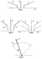
- Fig. 7
- schematische Darstellungen eines Steuerhebels, mit dem ein negativer Verstellgradient erzeugt wird;
- Fig. 1
- a scheme of a tax system;
- 2 and 3
- Flow diagrams of reversing aids;
- 4 to 6
- Different speed diagrams depending on the swivel angle of a control lever.
- Fig. 7
- schematic representations of a control lever with which a negative adjustment gradient is generated;
Die Drehzahl der Abtriebswelle 2 des Motors 1 kann über einen Drehzahlsensor 8 erfaßt werden. Ein weiterer Drehzahlsensor 9 ist der Propellerwelle 6 zugeordnet, um deren Drehzahl zu erfassen.The speed of the
Mit einem Fahrtrichtungssteller 10 wird das Getriebe 3 auf Vorwärts- bzw. Rückwärtsfahrt geschaltet. Ein Temperatursensor 11 überwacht die Betriebstemperatur der Kupplung 4.The
Die Drehzahlsensoren 8 und 9, der Kupplungsdrucksteller 5 und der Fahrtrichtungssteller 10 sind mit einem elektronischen Steuergerät 12 verbunden. Das Getriebe 3 mit den Sensor- und Steuermitteln 8, 9, 11 sowie 5 und 10 können zu einer Baueinheit 13 zusammengefaßt werden.The
Das elektronische Steuergerät ist über eine elektrische Leitung 14 an eine Steuerstation 15 angeschlossen. In die Leitung 14 mündet ein Anschluß eines Sensors 16 für die Schiffsgeschwindigkeit sowie ein Anschluß für einen Systemstecker 17, an den bedarfsweise ein Gerät zur Systemdiagnose angeschlossen werden kann.The electronic control unit is connected to a
Die Steuerstation 15 umfaßt eine Reihe von Kontroll-, Schalt- und Stellelementen. Im einzelnen handelt es sich hierbei um einen Befehlsgeber 18 für die Fahrtrichtung, einen Sollwertgeber 19 für die Drehzahl der Propellerwelle 6 im Langsamfahrt-Modus (Trolling-Modus), eine Kontrollampe 20, die dem Schiffsführer den ordnungsgemäßen Betrieb der Antriebsanlage anzeigt, sowie zwei Warnleuchten 21 und 22, die Abweichungen vom ordnungsgemäßen Betrieb signalisieren. Ein Betriebsschalter 23 dient dazu, den Betriebs-Modus "Langsamfahrt" (Trolling) anzuwählen und ein weiterer Betriebsschalter 24 ist vorgesehen, um eine Umsteuerhilfe vorzuwählen. Bei der Taste 25 handelt es sich um einen Notschalter, und mit der Taste 26 wird die Stromversorgung ein- bzw. ausgeschaltet.The
Ein wesentliches Merkmal der Erfindung besteht darin, daß der Schiffsführer im Langsamfahrt-Modus, das heißt im Trolling-Betrieb (Betriebsschalter 23 ist betätigt), die Möglichkeit hat, von Umsteuerhilfen Gebrauch zu machen. Mit Hilfe des Betriebsschalters 24 kann der Schiffsführer eine bestimmte Umsteuerhilfe - je nach seinen Bedürfnissen - vorwählen. Die vorgewählte Umsteuerhilfe wird aktiviert, wenn dem elektronischen Steuergerät 12 ein bestimmtes Steuersignal übermittelt wird.An essential feature of the invention is that the skipper has the possibility of making use of reversing aids in the slow travel mode, that is to say in the trolling mode (operating
Das Ablaufdiagramm nach Fig. 2 verdeutlicht, wie eine Umsteuerhilfe, die halbautomatisch abläuft, wirkt. Das Schiff wird bei einer bestimmten Motordrehzahl, beispielsweise von 900 U/min angetrieben. Zunächst ist das Getriebe 3 im Rückwärtsgang geschaltet (zweites Bild von oben). Das Schiff bewegt sich im Langsamfahrt-Modus bei einer Propellerwellendrehzahl von 100 U/min rückwärts. Die Kupplung 4 arbeitet im geregelten, schlupfenden Betrieb, d. h., sie ist mit einem bestimmten Kupplungsdruck beaufschlagt, der eine Relativbewegung zwischen den Lamellenpaketen zuläßt (vergleiche viertes Bild von oben). Die Propellerwellendrehzahl entspricht im Absolutbetrag der Trolling-Solldrehzahl von 100 U/min. Das Vorzeichen ist wegen der Rückwärtsfahrt negativ. Das Schiff bewegt sich beispielsweise mit einer Rückwärtsfahrgeschwindigkeit von drei Knoten. Soll nun aus der Rückwärtsfahrt heraus reversiert werden, wird das Getriebe über eine Neutralstellung in die Vorwärtsfahrtrichtung geschaltet (zweites Bild von oben). Der Kupplungsdruck wird in der Neutralstellung des Getriebes vollständig abgebaut. Mit dem Schalten der Vorwärtsfahrtrichtung wird die Kupplung vollständig geschlossen, so daß der Kupplungsdruck schnell sein Maximum erreicht (vergleiche viertes Bild von oben). Die Propellerwellendrehzahl beginnt zu steigen und erreicht ihr Maximum im vorliegenden Ausführungsbeispiel bei 400 U/min. Dieser Drehzahlwert ist abhängig von der herrschenden Motordrehzahl und der Getriebeübersetzung. Die Schiffsgeschwindigkeit verlangsamt sich, geht durch Null und beginnt in Vorwärtsfahrtrichtung zu steigen (vergleiche unterste Abbildung).2 illustrates how a reversing aid, which runs semi-automatically, works. The ship is propelled at a certain engine speed, for example 900 rpm. First, the
Mit dem vollständigen Schließen der Kupplung wird das Schiff mit einer aktuellen Propellerwellendrehzahl, die von verschiedenen Einflüssen, zum Beispiel der Motordrehzahl, dem Kupplungsdruck, den Strömungsverhältnissen usw. abhängig ist, beschleunigt. Der Schiffsführer beobachet die Reaktion des Schiffes. Sobald ihm die Schiffsreaktion ausreichend erscheint, beendet er die Beschleunigungsphase in folgender Weise:
Ein Steuerhebel 27, mit dem die Trolling-Soll-Drehzahl eingestellt wird, wird kurzzeitig im Sinne einer Reduzierung der eingestellten Trolling-Soll-Drehzahl verstellt. Bei diesem kurzzeitigen Zurücknehmen wird ein negativer Verstellgradient erzeugt, der dem Steuergerät 12 übermittelt wird. Von dem Steuergerät 12 wird dieses Steuersignal dahingehend interpretiert, daß die Beschleunigungsphase beendet werden soll. Das kurzzeitige Zurücknehmen der eingestellten Trolling-Soll-Drehzahl ist (dritte Abbildung von oben) dadurch schematisch angedeutet, daß in der ansonsten als gerade verlaufenden Kennlinie der Trolling-Soll-Drehzahl eine Einkerbung ersichtlich ist. Sobald die Steuerelektronik das Steuersignal empfangen hat, wird der Kupplungsdruck auf einen Wert reduziert, der dem Kupplungsdruck entspricht, wie er der Trolling-Soll-Drehzahl bzw. der Propellerwellendrehzahl bzw. einer gewünschten Schiffsgeschwindigkeit entspricht.When the clutch is fully closed, the ship is accelerated at a current propeller shaft speed which is dependent on various influences, for example the engine speed, the clutch pressure, the flow conditions, etc. The skipper observes the reaction of the ship. As soon as the ship reaction seems sufficient, he ends the acceleration phase in the following way:
A
Die Wirksamkeit der Umsteuerhilfe wird bei Betrachtung der unteren Abbildung der Fig. 2 deutlich. Nach Schalten der Vorwärtsfahrtrichtung und nach Durchlaufen der Schiffsgeschwindigkeit von Null steigt die Schiffsgeschwindigkeit in Vorwärtsfahrtrichtung relativ schnell an, bis der Schiffsführer durch Erzeugen des Steuersignals auf die vorstehend beschriebene Art und Weise die Beschleunigungsphase beendet. Dieses Zeitverhalten ist in der unteren Abbildung mit den durchgezogenen dicken Linien gekennzeichnet. Im Vergleich hierzu zeigt die gestrichelte Linie 28 das Zeitverhalten des Schiffes ohne Umsteuerhilfe. Ersichtlich ist, daß die gewünschte Schiffsgeschwindigkeit in Vorwärtsfahrtrichtung zu einem vergleichsweise sehr viel späteren Zeitpunkt erreicht wird.The effectiveness of the reversal aid becomes clear when considering the lower illustration in FIG. 2. After switching the forward direction of travel and after passing through the ship's speed from zero, the ship's speed in the forward direction of travel increases relatively quickly until the ship's master ends the acceleration phase by generating the control signal in the manner described above. This time behavior is indicated by the solid thick lines in the illustration below. In comparison, the dashed
Eine weitere Umsteuerhilfe, die mit der vorstehend erläuterten verwandt ist, besteht darin, daß im Trolling-Betrieb die Kupplung 4 nach Schalten der Vorwärtsfahrtrichtung zunächst vollständig geschlossen wird. Dadurch wird das Schiff mit einem Schub beschleunigt, der der gewählten Motordrehzahl proportional ist. Sobald das Schiff unter Berücksichtigung der Systemdynamik die gewünschte Geschwindkeit erreicht hat, unterbricht die Steuerelektronik 12 die Beschleunigung mit geschlossener Kupplung und stellt die Trolling-Drehzahl an der Propellerwelle ein, bis die Soll-Geschwindigkeit erreicht ist. Zur Ermittlung der Geschwindigkeit dient der erwähnte Sensor 16. Im Unterschied zur ersten Umsteuerhilfe kann diese Art der Umsteuerhilfe automatisiert ablaufen.Another reversing aid, which is related to that explained above, consists in the fact that in trolling mode the clutch 4 is initially completely closed after switching the forward direction. This accelerates the ship with a thrust that is proportional to the selected engine speed. As soon as the ship takes into account the system dynamics has reached the desired speed, the
Aus der Abbildung entsprechend Fig. 3 ist eine dritte Möglichkeit einer Umsteuerhilfe zu ersehen. Aus der vierten Abbildung von oben geht hervor, daß die Kupplung 4 beim Schalten der Vorwärtsfahrtrichtung zunächst so weit geschlossen wird, daß sich unmittelbar die vorgewählte Trolling-Drehzahl und Drehrichtung an der Propellerwelle 6 einstellt. Die Steuerelektronik 12 hält auch die Propellerwellendrehzahl konstant, und zwar entgegen einem am Propeller 7 wirkenden Turbinen-Antriebsmoment. Die erläuterte Umsteuerhilfe ist besonders dann vorteilhaft einzusetzen, wenn Manöver gefahren werden sollen, die eine langsame Geschwindigkeitssteigerung erfordern, wie dies zum Beispiel beim Anschleppen erwünscht ist.A third possibility of a reversal aid can be seen from the illustration corresponding to FIG. 3. From the fourth illustration from above it can be seen that when the forward direction is switched, the clutch 4 is initially closed to such an extent that the preselected trolling speed and direction of rotation are set on the propeller shaft 6. The
Mit dem Betriebsschalter 24 kann eine Umsteuerhilfe an- bzw. vorgewählt werden. Besonders flexibel ist das erfindungsgemäße Steuersystem dann, wenn sämtliche Umsteuerhilfen auf Wunsch verfügbar sind. In diesem Fall hat der Schiffsführer die Möglichkeit, über den Betriebsschalter 24 eine - aus insgesamt drei verfügbaren - Umsteuerhilfe 4 vorzuwählen. Die Antriebsanlage des Schiffes wird in diesem Fall für praktische Verhältnisse jeder Situation gerecht.A reversing aid can be selected or preselected with the operating
Den Diagrammen entsprechend den Fig. 4 bis 6 lassen sich die Drehzahlverhältnisse in Abhängigkeit der Schwenkwinkel der ihnen zugeordneten Steuerhebel entnehmen. Dem Diagramm entsprechend Fig. 4 liegt ein Deckschalter zugrunde, der zwei Steuerhebel aufweist. Ein erster Steuerhebel erlaubt das Schalten einer bestimmten Fahrtrichtung und das Einstellen einer bestimmten Motordrehzahl . Ein weiterer Steuerhebel läßt die Einstellung einer bestimmten Trolling-Soll-Drehzahl zu.The diagrams corresponding to FIGS. 4 to 6 show the speed ratios as a function of the swivel angle of the control levers assigned to them. 4 is based on a deck switch which has two control levers. A first control lever allows you to switch a certain direction of travel and set a certain engine speed. Another control lever allows the setting of a specific target trolling speed.
Dem Diagramm nach Fig. 5 liegt ein Deckschalter mit einem Steuerhebel zugrunde. Mit diesem Steuerhebel kann eine bestimmte Fahrtrichtung und eine bestimmte Motordrehzahl vorgewählt werden. In dem Bereich, in dem Motordrehzahlen eingestellt werden können, die auch für den Trolling-Betrieb zulässig bzw. geeignet sind, ist die Anordnung so getroffen, daß eine Überlagerung der Sollwerteinstellung für eine Trolling-Drehzahl selbsttätig mit Priorität stattfindet. Diese Bereiche, in denen dann im Langsamfahrt-Modus gefahren wird, sind mit gestrichelten Linien 31 eingezeichnet. Es ist vorteilhaft, daß die Drehzahlen so überlagert werden, daß bei einer minimalen Motordrehzahl eine minimale Trolling-Drehzahl eingestellt wird. Der im Trolling-Betrieb maximal zulässigen Motordrehzahl ist dann die maximal mögliche Trolling-Drehzahl zugeordnet.5 is based on a deck switch with a control lever. This control lever can be used to preselect a specific direction of travel and a specific engine speed. In the area in which engine speeds can be set that are also permissible or suitable for trolling operation, the arrangement is such that the setpoint setting for a trolling speed is automatically superimposed with priority. These areas, in which the vehicle is then driven in slow travel mode, are shown with dashed
Dem Diagramm entsprechend Fig. 6 liegt ein Deckschalter zugrunde, der entweder einen oder auch zwei Steuerhebel aufweisen kann. Im Reise-Modus wird mit einem bzw. beiden Steuerhebeln die Fahrtrichtung geschaltet und eine Motordrehzahl eingestellt (durchgezogene Linie). Im Trolling-Betrieb ist mit einem Steuerhebel eine Vorgabe der Trolling-Propellerwellendrehzahl möglich (gestrichelte Linien). Das elektronische Steuergerät 12 bzw. eine gesonderte Motorelektronik ordnet einer vorgewählten Trolling-Drehzahl eine bestimmte Motor-Drehzahl zu. Diese Zuordnung erfolgt in Abhängigkeit bestimmter Betriebsparameter des Motors bzw. des Getriebes. Bei diesen Betriebsparametern handelt es sich um charakteristische Kenngrößen, wie beispielsweise den Kraftstoffverbrauch, die thermische Belastung der Kupplung oder auch Abgasemissionswerten.6 is based on a deck switch, which can have either one or two control levers. In travel mode, the direction of travel is switched with one or both control levers and an engine speed is set (solid line). In trolling mode, a control lever can be used to specify the trolling propeller shaft speed (dashed line Lines). The
In Fig. 7 ist schematisch der Steuerhebel 27 oder Fahrschalter, mit dem eine Trolling-Drehzahl eingestellt werden kann, abgebildet. Der Steuerhebel 27 ist zwischen zwei Endlagen (z. B. 0 % und 100 %) schwenkbar. In einem Sektor 29, der sich an eine Endlage (0 %) anschließt, ist der Steuerhebel 27 nur gegen einen Widerstand, beispielsweise die Kraft einer Druckfeder 30, im Sinne einer weiteren Reduzierung verschwenkbar. Mit dieser Maßnahme wird erreicht, daß ein negativer Verstellgradient auch dann erzeugt werden kann, wenn sich der Steuerhebel 27 in einer Endlage befindet, aus der heraus eine weitere Reduzierung der Trolling-Solldrehzahl tatsächlich nicht mehr möglich ist. Die vorstehend erläuterte Maßnahme erhöht die passive Sicherheit des Systems.In Fig. 7, the
- 11
- Motorengine
- 22nd
- AbtriebswelleOutput shaft
- 33rd
- Getriebetransmission
- 44th
- Kupplungclutch
- 55
- KupplungsdruckstellerClutch pressure regulator
- 66
- PropellerwellePropeller shaft
- 77
- Propellerpropeller
- 88th
- DrehzahlsensorSpeed sensor
- 99
- DrehzahlsensorSpeed sensor
- 1010th
- FahrtrichtungsstellerDirection switch
- 1111
- TemperatursensorTemperature sensor
- 1212th
- SteuerelektronikControl electronics
- 1313
- BaueinheitUnit
- 1414
- elektrische Leitungelectrical line
- 1515
- SteuerstationControl station
- 1616
- Sensor für SchiffsgeschwindigkeitShip speed sensor
- 1717th
- SystemsteckerSystem connector
- 1818th
- BefehlsgeberCommanders
- 1919th
- SollwertgeberSetpoint generator
- 2020th
- KontrollampeIndicator lamp
- 2121
- WarnleuchteWarning light
- 2222
- WarnleuchteWarning light
- 2323
- BetriebsschalterOperation switch
- 2424th
- BetriebsschalterOperation switch
- 2525th
- Tastebutton
- 2626
- Tastebutton
- 2727
- Steuerhebel, FahrschalterControl lever, drive switch
- 2828
- gestrichelte Liniedashed line
- 2929
- Sektorsector
- 3030th
- DruckfederCompression spring
- 3131
- gestrichelte Liniedashed line
Claims (8)
- Control system for operating a drive installation in a ship with at least one engine (1) which drives a propeller shaft (6) via a gearbox (3) with at least one regulable clutch (4) for forward and backward motion, with control and sensor means (5, 8, 9, 10, 11, 12, 16, 17, 27) for influencing the rotational speed of the engine and/or the degree of slipping of the clutch (4) with at least one control station (15) with control means (18 - 26) for setting the direction of motion and speed of the ship by actuating at least one control lever (27) and also control electronics (12) for processing input and output signals, characterized in that, in one type of operation (slow motion mode or trolling) of the drive installation, the clutch (4) is completely closed after switching the direction of motion and the acceleration phase is ended by transmitting a control signal, which is the negative adjusting gradient of a control lever resulting from a reduction of the trolling rotational speed, to the control electronics (12) by bringing the clutch (4) over into the regulated slipping operation.
- Control system according to the pre-characterizing clause of claim 1, characterized in that, in one type of operation (slow motion mode or trolling) of the drive installation, the clutch (4) is completely closed after switching the direction of motion, and the acceleration phase is ended by transmitting a control signal, which indicates that a defined speed of the ship has been reached, to the control electronics (12), with the clutch (4) closed, by setting the rotational speed of the propeller shaft (6) to a trolling rotational speed.
- Control system according to the pre-characterizing clause of claim 1, characterized in that, in one type of operation (slow motion mode or trolling) of the drive installation, the clutch (4) is closed to an extent such that the preselected trolling rotational speed and direction of rotation is set at the propeller shaft (6) and the control electronics (12) keep the preselected rotational speed of the propeller shaft constant in the transitional range in which the propeller (7) is able to act as a turbine.
- Control system with a control station (15) via which the manner of operation of the drive installation is controllable, as claimed in one of claims 1, 2 or 3, characterized in that means (operating switch 24) are present for preselecting a reversing sequence.
- Control system with at least one control station (15) with at least one control lever, which is pivotable between two end positions for the purpose of selecting the speed of motion, as claimed in claim 1, characterized in that the control lever (27) is adjustable, in a range bordering on one of the end positions, against a resistance.
- Control system with at least one control station (15) with a control lever for selecting the speed of motion by adjusting the rotational speed of the engine in the cruise mode, as claimed in claims 1 to 3, characterized in that, in one range of the control lever, in which rotational speeds of the engine which are admissible for slow motion can be set, superimposition of the setting of the ideal value for the rotational speed of the propeller shaft takes place with priority, so that the drive installation is operated in the slow motion mode in this range.
- Control system according to claim 6, characterized in that the superimposition is effected by electrical means.
- Control system according to one of claims 1, 2 or 3, characterized in that a rotational speed of the engine which is dependent upon operating parameters is automatically assigned to a preselected rotational speed of the propeller shaft by the control electronics (12).
Applications Claiming Priority (3)
| Application Number | Priority Date | Filing Date | Title |
|---|---|---|---|
| DE4125432A DE4125432A1 (en) | 1991-08-01 | 1991-08-01 | CONTROL SYSTEM FOR OPERATING A DRIVE SYSTEM FOR A SHIP |
| DE4125432 | 1991-08-01 | ||
| PCT/EP1992/001709 WO1993002914A1 (en) | 1991-08-01 | 1992-07-28 | Control system for operating the drive assembly of a ship |
Publications (2)
| Publication Number | Publication Date |
|---|---|
| EP0595977A1 EP0595977A1 (en) | 1994-05-11 |
| EP0595977B1 true EP0595977B1 (en) | 1995-10-11 |
Family
ID=6437448
Family Applications (1)
| Application Number | Title | Priority Date | Filing Date |
|---|---|---|---|
| EP92916358A Expired - Lifetime EP0595977B1 (en) | 1991-08-01 | 1992-07-28 | Control system for operating the drive assembly of a ship |
Country Status (5)
| Country | Link |
|---|---|
| US (1) | US5474480A (en) |
| EP (1) | EP0595977B1 (en) |
| JP (1) | JP3448054B2 (en) |
| DE (2) | DE4125432A1 (en) |
| WO (1) | WO1993002914A1 (en) |
Cited By (2)
| Publication number | Priority date | Publication date | Assignee | Title |
|---|---|---|---|---|
| DE102005001552A1 (en) * | 2005-01-13 | 2006-07-27 | Zf Friedrichshafen Ag | Water vehicle driving system, has clutch driving propeller shaft in fast and slow driving modes that are combined into combined mode, which allows forward/backward operation of drive system during deflection of lever from neutral position |
| DE102008025480B3 (en) * | 2008-05-27 | 2009-12-24 | Robert Bosch Gmbh | Control device and method for influencing the engine speed and the degree of slip of a coupling of a marine propulsion system |
Families Citing this family (16)
| Publication number | Priority date | Publication date | Assignee | Title |
|---|---|---|---|---|
| FR2729637B1 (en) * | 1995-01-19 | 1997-04-18 | Semt Pielstick | DEVICE AND METHOD FOR ADJUSTING THE SPEED OF A VESSEL |
| JP3804030B2 (en) * | 1995-07-05 | 2006-08-02 | ヤマハマリン株式会社 | Ship propulsion machine |
| US6679740B1 (en) * | 1999-09-02 | 2004-01-20 | Yanmar Diesel Engine Co., Ltd. | Method of hydraulically controlling a marine speed reducing and reversing machine in crash astern operation |
| CA2306291A1 (en) * | 2000-04-20 | 2001-10-20 | Wayne Ernest Conrad | Method and apparatus for improving the speed and fuel economy ¬hence endurance (range)| of aircraft, surface vessels, sub-surface vessels, missiles and torpedoes and/or altering the acoustic signature of such aircraft, surface vessels, sub-surface vessels, missiles or torpedoes |
| FR2810294B1 (en) * | 2000-06-20 | 2003-02-07 | Roland Auguste Jean Chardey | SAFETY DEVICE FOR FISHING VESSELS |
| DE10048103C2 (en) * | 2000-09-28 | 2002-09-05 | Mtu Friedrichshafen Gmbh | Control system for a ship propulsion |
| US7377827B1 (en) * | 2003-06-20 | 2008-05-27 | Sturdy Corporation | Marine propulsion shift control |
| KR20060083222A (en) * | 2003-10-20 | 2006-07-20 | 노티텍 피티와이 리미티드 | De-coupling clutch, particularly for marine use |
| CN100532194C (en) * | 2004-04-22 | 2009-08-26 | 诺蒂泰克控股有限公司 | Decoupler |
| JP4641312B2 (en) * | 2007-07-06 | 2011-03-02 | 三菱電機株式会社 | Electronic controller for ship drive |
| JP6062095B1 (en) * | 2016-06-09 | 2017-01-18 | 株式会社マリタイムイノベーションジャパン | Instruction device for ship propulsion engine |
| IT201700015579A1 (en) * | 2017-02-13 | 2018-08-13 | As Service Srl | INTEGRATED PROPULSION SYSTEM FOR BOATS |
| EP3823894A1 (en) * | 2018-07-19 | 2021-05-26 | ZF Friedrichshafen AG | Method to operate a marine propulsion system in a trolling mode, control unit and marine propulsion system |
| US11215128B1 (en) * | 2018-08-14 | 2022-01-04 | Brunswick Corporation | Acceleration control method for marine engine |
| WO2020110280A1 (en) * | 2018-11-30 | 2020-06-04 | 本田技研工業株式会社 | Engine speed control device for vessel |
| DE102019211756B3 (en) * | 2019-08-06 | 2020-12-24 | Zf Friedrichshafen Ag | Method, control device and computer program product for actuating a friction clutch of a drive train of a motorized watercraft |
Family Cites Families (5)
| Publication number | Priority date | Publication date | Assignee | Title |
|---|---|---|---|---|
| US2925156A (en) * | 1957-12-24 | 1960-02-16 | Gen Motors Corp | Drive control mechanism for prime mover with fluid actuated clutches |
| DE2558577A1 (en) * | 1975-12-24 | 1977-09-01 | Hanseatische Konstruktions Ges | Watercraft with variable speed reversible propulsion - has hydraulic motor driven separate from swashplate pump and under electrical control |
| JPS52137890A (en) * | 1976-05-12 | 1977-11-17 | Nippon Air Brake Co | Remote control device for marine main engine |
| SE457873C (en) * | 1987-04-30 | 1993-05-20 | Styr Kontrollteknik I Stockhol | MANUAL SYSTEM FOR MARKETING COSTS |
| US4836809A (en) * | 1988-03-11 | 1989-06-06 | Twin Disc, Incorporated | Control means for marine propulsion system |
-
1991
- 1991-08-01 DE DE4125432A patent/DE4125432A1/en not_active Withdrawn
-
1992
- 1992-07-28 JP JP50324193A patent/JP3448054B2/en not_active Expired - Fee Related
- 1992-07-28 DE DE59204009T patent/DE59204009D1/en not_active Expired - Lifetime
- 1992-07-28 EP EP92916358A patent/EP0595977B1/en not_active Expired - Lifetime
- 1992-07-28 WO PCT/EP1992/001709 patent/WO1993002914A1/en active IP Right Grant
- 1992-07-28 US US08/182,141 patent/US5474480A/en not_active Expired - Lifetime
Cited By (3)
| Publication number | Priority date | Publication date | Assignee | Title |
|---|---|---|---|---|
| DE102005001552A1 (en) * | 2005-01-13 | 2006-07-27 | Zf Friedrichshafen Ag | Water vehicle driving system, has clutch driving propeller shaft in fast and slow driving modes that are combined into combined mode, which allows forward/backward operation of drive system during deflection of lever from neutral position |
| DE102005001552B4 (en) * | 2005-01-13 | 2010-04-01 | Zf Friedrichshafen Ag | A watercraft propulsion system for operating a propulsion system of a watercraft |
| DE102008025480B3 (en) * | 2008-05-27 | 2009-12-24 | Robert Bosch Gmbh | Control device and method for influencing the engine speed and the degree of slip of a coupling of a marine propulsion system |
Also Published As
| Publication number | Publication date |
|---|---|
| WO1993002914A1 (en) | 1993-02-18 |
| JPH06509295A (en) | 1994-10-20 |
| EP0595977A1 (en) | 1994-05-11 |
| DE59204009D1 (en) | 1995-11-16 |
| JP3448054B2 (en) | 2003-09-16 |
| DE4125432A1 (en) | 1993-02-04 |
| US5474480A (en) | 1995-12-12 |
Similar Documents
| Publication | Publication Date | Title |
|---|---|---|
| EP0595977B1 (en) | Control system for operating the drive assembly of a ship | |
| DE3907841C2 (en) | ||
| DE3222054C2 (en) | ||
| DE2718831C2 (en) | Drive and control device for water vehicles | |
| EP2193073B1 (en) | Method for controlling a surface drive for a watercraft in the upper speed range | |
| DE3636953C2 (en) | ||
| DE10012122A1 (en) | Clutch control system for operating a motor vehicle clutch automatically utilizes an uncoupling fork and a slave cylinder triggered by an electronic control device regulating clutch operations with a hydraulic control. | |
| DE2328112B2 (en) | REGULATING DEVICE FOR THE FUEL SUPPLY AND FOR THE TRANSMISSION RATIO OF A DRIVE FOR MOTOR VEHICLES | |
| EP0524992B1 (en) | Control system for operating a ship's motive installation | |
| DE2844116A1 (en) | HYDROMECHANICAL TRANSMISSION FOR CONTINUOUSLY CHANGING THE RATIO OF AN INPUT AND OUTPUT SHAFT AND REVERSING THE DIRECTION OF ROTATION OF THE OUTPUT SHAFT | |
| DE2637345C2 (en) | Control device for a swiveling thrust generator, e.g. rudder propeller, of ships | |
| DE60013292T2 (en) | Switching synchronization that takes into account a falling torque | |
| DE4019687C2 (en) | Ship propulsion with trolling facility | |
| DE4112192A1 (en) | Control system for operating ship drive - controls revs of each engine or slip of clutch for coupling drive to propeller shaft | |
| DE3425757A1 (en) | SYNCHRONIZED MECHANICAL-HYDROSTATIC GEARBOX | |
| DE60012507T2 (en) | AUTOMATIC SERVO DEVICE FOR A SEQUENTIAL TRANSMISSION AND FOR A COUPLING | |
| DE3334723A1 (en) | Device for the control of an engine and/or an automatic clutch of motor vehicles | |
| EP1661781B1 (en) | Method of detecting the direction of rotation of the secondary side of a starting clutch. | |
| DE102005001552B4 (en) | A watercraft propulsion system for operating a propulsion system of a watercraft | |
| DE3334724A1 (en) | Device for the automatic or semi-automatic control of an engine and a clutch of a motor vehicle | |
| EP1107908B1 (en) | Method for controlling a power-shift multi-speed boat transmission | |
| DE19861303A1 (en) | Multi-step transmission and method for designing a gear of a stepped transmission | |
| DE2056521A1 (en) | Gear change transmissions in group design for motor vehicles, in particular for farm and road tractors | |
| DE3733883A1 (en) | DRIVE FOR COMMERCIAL VEHICLES | |
| DE2501391A1 (en) | Tug propulsion systems, of Z-type - modified to improve manoeuvring characteristics and efficiency at low speed uses slipping clutch |
Legal Events
| Date | Code | Title | Description |
|---|---|---|---|
| PUAI | Public reference made under article 153(3) epc to a published international application that has entered the european phase |
Free format text: ORIGINAL CODE: 0009012 |
|
| 17P | Request for examination filed |
Effective date: 19931123 |
|
| AK | Designated contracting states |
Kind code of ref document: A1 Designated state(s): BE DE FR GB IT |
|
| 17Q | First examination report despatched |
Effective date: 19940912 |
|
| ITF | It: translation for a ep patent filed |
Owner name: DE DOMINICIS & MAYER S.R.L. |
|
| GRAA | (expected) grant |
Free format text: ORIGINAL CODE: 0009210 |
|
| AK | Designated contracting states |
Kind code of ref document: B1 Designated state(s): BE DE FR GB IT |
|
| GBT | Gb: translation of ep patent filed (gb section 77(6)(a)/1977) |
Effective date: 19951016 |
|
| REF | Corresponds to: |
Ref document number: 59204009 Country of ref document: DE Date of ref document: 19951116 |
|
| ET | Fr: translation filed | ||
| PLBQ | Unpublished change to opponent data |
Free format text: ORIGINAL CODE: EPIDOS OPPO |
|
| PLBI | Opposition filed |
Free format text: ORIGINAL CODE: 0009260 |
|
| PLBF | Reply of patent proprietor to notice(s) of opposition |
Free format text: ORIGINAL CODE: EPIDOS OBSO |
|
| 26 | Opposition filed |
Opponent name: RENK AKTIENGESELLSCHAFT Effective date: 19960709 |
|
| PLBF | Reply of patent proprietor to notice(s) of opposition |
Free format text: ORIGINAL CODE: EPIDOS OBSO |
|
| PLBF | Reply of patent proprietor to notice(s) of opposition |
Free format text: ORIGINAL CODE: EPIDOS OBSO |
|
| PLBO | Opposition rejected |
Free format text: ORIGINAL CODE: EPIDOS REJO |
|
| PLBN | Opposition rejected |
Free format text: ORIGINAL CODE: 0009273 |
|
| STAA | Information on the status of an ep patent application or granted ep patent |
Free format text: STATUS: OPPOSITION REJECTED |
|
| 27O | Opposition rejected |
Effective date: 19970810 |
|
| REG | Reference to a national code |
Ref country code: GB Ref legal event code: IF02 |
|
| PGFP | Annual fee paid to national office [announced via postgrant information from national office to epo] |
Ref country code: FR Payment date: 20060719 Year of fee payment: 15 |
|
| PGFP | Annual fee paid to national office [announced via postgrant information from national office to epo] |
Ref country code: GB Payment date: 20060726 Year of fee payment: 15 |
|
| GBPC | Gb: european patent ceased through non-payment of renewal fee |
Effective date: 20070728 |
|
| PG25 | Lapsed in a contracting state [announced via postgrant information from national office to epo] |
Ref country code: GB Free format text: LAPSE BECAUSE OF NON-PAYMENT OF DUE FEES Effective date: 20070728 |
|
| REG | Reference to a national code |
Ref country code: FR Ref legal event code: ST Effective date: 20080331 |
|
| PG25 | Lapsed in a contracting state [announced via postgrant information from national office to epo] |
Ref country code: FR Free format text: LAPSE BECAUSE OF NON-PAYMENT OF DUE FEES Effective date: 20070731 |
|
| PGFP | Annual fee paid to national office [announced via postgrant information from national office to epo] |
Ref country code: IT Payment date: 20100724 Year of fee payment: 19 Ref country code: DE Payment date: 20100721 Year of fee payment: 19 |
|
| PGFP | Annual fee paid to national office [announced via postgrant information from national office to epo] |
Ref country code: BE Payment date: 20100714 Year of fee payment: 19 |
|
| BERE | Be: lapsed |
Owner name: *ZF FRIEDRICHSHAFEN A.G. Effective date: 20110731 |
|
| PG25 | Lapsed in a contracting state [announced via postgrant information from national office to epo] |
Ref country code: BE Free format text: LAPSE BECAUSE OF NON-PAYMENT OF DUE FEES Effective date: 20110731 Ref country code: DE Free format text: LAPSE BECAUSE OF NON-PAYMENT OF DUE FEES Effective date: 20120201 |
|
| REG | Reference to a national code |
Ref country code: DE Ref legal event code: R119 Ref document number: 59204009 Country of ref document: DE Effective date: 20120201 |
|
| PG25 | Lapsed in a contracting state [announced via postgrant information from national office to epo] |
Ref country code: IT Free format text: LAPSE BECAUSE OF NON-PAYMENT OF DUE FEES Effective date: 20110728 |