EP0595763A2 - Cutter bar with a high wear resistance and method of making it - Google Patents
Cutter bar with a high wear resistance and method of making it Download PDFInfo
- Publication number
- EP0595763A2 EP0595763A2 EP93810641A EP93810641A EP0595763A2 EP 0595763 A2 EP0595763 A2 EP 0595763A2 EP 93810641 A EP93810641 A EP 93810641A EP 93810641 A EP93810641 A EP 93810641A EP 0595763 A2 EP0595763 A2 EP 0595763A2
- Authority
- EP
- European Patent Office
- Prior art keywords
- carrier
- knife
- hard material
- cutting bar
- bar according
- Prior art date
- Legal status (The legal status is an assumption and is not a legal conclusion. Google has not performed a legal analysis and makes no representation as to the accuracy of the status listed.)
- Granted
Links
Images

Classifications
-
- B—PERFORMING OPERATIONS; TRANSPORTING
- B02—CRUSHING, PULVERISING, OR DISINTEGRATING; PREPARATORY TREATMENT OF GRAIN FOR MILLING
- B02C—CRUSHING, PULVERISING, OR DISINTEGRATING IN GENERAL; MILLING GRAIN
- B02C18/00—Disintegrating by knives or other cutting or tearing members which chop material into fragments
- B02C18/06—Disintegrating by knives or other cutting or tearing members which chop material into fragments with rotating knives
- B02C18/16—Details
- B02C18/18—Knives; Mountings thereof
- B02C2018/188—Stationary counter-knives; Mountings thereof
Definitions
- the present invention relates to cutting strips, which are preferably used in cooperation with cutting rotors, inter alia for the production of granules, and to a method for producing such cutting strips.
- Knives which consist entirely of hard metal or of a support made of steel and a knife made of hard metal soldered thereon. This solder connection is problematic in itself, since hard metal is poorly wetted by the common soldering materials, but the reject rate is still within acceptable limits. However, the relatively soft steel beam is subject to a high degree of abrasion, which limits the life of such cutting strips.
- Both materials, PCD and CBN, are commercially available as a layer structure consisting of a carrier, which in the context of the present invention consists of a hard metal and is called a knife carrier, and an associated layer or coating of a hard material. In principle, strips made of this material can be used as knives for cutting strips.
- the knife carrier is chemically changed when the hard material layer is applied, specifically the carrier is enriched with carbon, and it is also not always possible to select the optimal materials for the carrier for the respective application.
- the hard-coated knives such as the hard-metal knives previously, are to be soldered onto another carrier in order to obtain a cutting bar.
- the hard-coated knives can be soldered onto a carrier even more poorly than hard-metal knives. This is primarily attributed to the above-mentioned carbon enrichment in the knife holder.
- the knife carrier material is subject to wear where it comes to the surface of the cutting bar, and all the more because the knife carrier material loses part of its wear resistance during the application of the hard material layer.
- Such a cutting bar is specified in claim 1.
- the further claims include preferred designs, methods for producing the cutting bar according to the invention and types of use.
- the cutting bar according to the invention consists of a carrier which preferably consists of a highly wear-resistant hard metal and onto which a knife coated with a hard material is soldered.
- the contact surface of the knife carrier is shaped in such a way that the carrier closes with the hard material at most with a functionally negligible joint on the surfaces exposed to the material to be processed.
- connection point between the cutting edge support and the knife is preferably made by soldering.
- the surfaces to be soldered are provided with a solder-friendly metal layer. This is preferably done according to the method described in the applicant's Swiss patent specification CH-649 089, which is hereby incorporated into the description.
- a metal layer of a few micrometers to a few 100 micrometers is applied and alloyed into the surface of the hard metal at high temperature, which not only creates a solder-friendly surface, but also fills up existing surface irregularities (voids) with the metal.
- Nickel is particularly suitable for surface treatment for price reasons.
- Other metals are possible, e.g. B. silver, copper or cobalt.
- One embodiment of the invention consists of the hard material knife and the carrier, the carrier having the necessary fastening devices in order to be able to fasten the bar, for example in a cutting machine.
- a preferred embodiment of the invention consists in fastening the carrier on a holder by means of a releasable connection technique. This makes it possible to replace worn or damaged sections of the cutting edge.
- the holder can also be made in a less wear-resistant material, which on the other hand, for example, an easier attachment of fasteners such.
- an undercut groove ie a groove that widens towards the bottom, is incorporated into the knife carrier, into which suitable slot nuts can be inserted as anchors.
- the sliding blocks are connected to the carrier using suitable fastening elements. You can e.g. B. z. B. have holes with an internal thread, whereby they by means of screws which are inserted through the carrier, can be used and fix the hard material knife on the carrier.
- the known hard material cutting strip 1 shown in FIG. 1 consists of a carrier 2 onto which the hard material knife 3 is soldered.
- the hard material knife consists of the knife carrier 4, on which the hard material layer 5 is applied.
- the hard material 5 is preferably polycrystalline diamond (PCD) or cubic boron nitride (CBN).
- the exposed flanks 6 of the knife carrier 4 are exposed to wear in the conventional cutting bar 1 (FIG. 1). After a short time, the hard material layer 5 is undermined, which leads to damage to the cutting edge. 2, this problem can be solved according to the invention in that the knife 3 is inserted into a V-shaped groove in the carrier 2, for which purpose the flanks 6 of the knife carrier 4 are removed in mirror image to the shape of the groove. The resulting bevels preferably extend without borders to the hard material layer 5. After insertion, the sides of the carrier 2 can be ground to the mass of the knife 3.
- the second problem area is the soldered connection 7 between the knife carrier 4 and the carrier 2.
- the knife carrier 4 has an excess of carbon which on the one hand worsens the mechanical properties of the carrier material 4 and on the other hand also reduces the solderability. Even or especially when inserting the knife 3 into a V-groove, an insufficient reliability of the connection between the carrier 2 and the knife 3 was found in practice. Since with the V-groove the forces occurring during cutting are converted to a greater extent into shear stresses, with the V-groove the quality of the connection between carrier 2 and knife 3 is of increased importance.
- the surface 7 of the knife carrier 4 can be metallized at high temperatures and thus made solder-friendly, preferably according to the method as described in CH-649 098. Contrary to the expectation that the hard material layer would be attacked at the temperatures necessary for the metallization and, in the worst case, decomposed, no such effects were surprisingly observed to any appreciable extent if the metallization was carried out in an inert, at least oxygen-free atmosphere or in a vacuum.
- the reliable solder connection achieved in this way allows the advantages of the V connection to be exploited.
- the knife according to the invention achieves a long service life since highly wear-resistant supports 2 can be used, and can be used in high yield. The risk of the knife detaching from the carrier 2 during operation is reduced to an insignificant value by the high quality solder connection. It is also advantageous that the cutting bar according to the invention can have two cutting edges, as a result of which the service life is increased again. With the knife according to the invention, tool life of 1 2nd a per cutting edge, after which the second cutting edge can be used by turning the bar.
- two fastening elements such as holes, inserted threaded bushings, etc., are present on the carrier in order to fasten the arrangement at the place of use.
- the cutting bar 1 is connected to a holder 8 which has the fastening elements mentioned above. Since the holder 8 is no longer exposed to the effects of abrasion to the extent that the cutting bar 1, other suitable materials can also be used in addition to hard metal, such as, for. B. stainless steel, in which the fasteners are easier to attach.
- 3 shows transverse holes 12 as an example.
- connection between holder 8 and carrier 2 is preferably releasable, for. B. by means of screw elements.
- a preferred solution is to provide at least one bore in the carrier 2, into which a threaded rod 9 is inserted and permanently attached, e.g. B. is soldered.
- a corresponding bore 10 is provided in the holder 8, through which the threaded rod 9 projects.
- a nut 11 is screwed onto the threaded rod 9 and tightened.
- Another version uses a screw instead of the threaded rod, which is screwed into a threaded bushing inserted in the carrier 2.
- an undercut groove 15 is machined into the carrier 4 in the longitudinal direction of the hard material knife 3.
- slot nuts 16 can be used, into which a thread is cut.
- a screw 17 is passed from below through a bore 18 in the carrier 2 and screwed into a slot nut 16, as a result of which the hard material knife 3 is fixed on the carrier 2 in the V-groove.
- At least 2 slot nuts are preferably provided for fastening per hard material knife.
- the bore 18 is preferably designed such that the head of the screw 17 is countersunk in the carrier. By choosing the depth this recess can also be adapted to the length of the screws 17 available.
- the groove 15 is preferably produced in the knife carrier 4 by means of erosion. This is simply done in one step with the production of the oblique flanks of the knife carrier 4.
- the cutting bar can be attached to an additional holder 8 analogously to the embodiment according to FIG. 3.
Landscapes
- Engineering & Computer Science (AREA)
- Food Science & Technology (AREA)
- Forging (AREA)
- Wire Processing (AREA)
- Knives (AREA)
- Drilling Tools (AREA)
- Crushing And Pulverization Processes (AREA)
- Nonmetal Cutting Devices (AREA)
- Excavating Of Shafts Or Tunnels (AREA)
Abstract
Description
Die vorliegende Erfindung bezieht sich auf Schneidleisten, die bevorzugt im Zusammenwirken mit Schneidrotoren unter anderem zur Granulatherstellung eingesetzt werden, sowie auf ein Verfahren zur Herstellung derartiger Schneidleisten.The present invention relates to cutting strips, which are preferably used in cooperation with cutting rotors, inter alia for the production of granules, and to a method for producing such cutting strips.
Als Gegenwerkzeug zu Schneidrotoren sind Schneidleisten hohen abrasiven Beanspruchungen ausgesetzt. Dabei ist nicht nur die Schneidzone selbst betroffen, sondern auch die umliegende Oberfläche der Schneidleiste, wodurch die mit mässigem Aufwand aus hochverschleissfestem Material ausführbare Schneidkante sozusagen unterminiert wird, d. h. ihre mechanische Stabilität wird geschwächt. Falls die Schneidleiste nicht regelmässig darauf kontrolliert wird, können Teile aus der Schneidkante herausbrechen, und schliesslich kann die Schneidkante abbrechen. In der Folge treten oft schwere Schäden an der Maschine und besonders am Schneidrotor auf.As a counter tool to cutting rotors, cutting strips are exposed to high abrasive loads. This affects not only the cutting zone itself, but also the surrounding surface of the cutting bar, which means that the cutting edge, which can be made of highly wear-resistant material with moderate effort, is undermined, so to speak. H. their mechanical stability is weakened. If the cutting bar is not checked regularly, parts can break out of the cutting edge and finally the cutting edge can break off. As a result, severe damage to the machine and especially the cutting rotor often occurs.
Bekannt sind Schneidleisten, die ganz aus Hartmetall oder aus einem Träger aus Stahl und einem darauf gelöteten Messer aus Hartmetall bestehen. Diese Lötverbindung ist an sich schon problematisch, da Hartmetall nur schlecht von den gängigen Lötmaterialien benetzt wird, die Auschussrate liegt jedoch noch in akzeptabeln Grenzen. Allerdings unterliegt der relativ weiche Stahlträger in hohem Masse der Abrasion, wodurch die Lebensdauer derartiger Schneidleisten begrenzt ist.Knives are known which consist entirely of hard metal or of a support made of steel and a knife made of hard metal soldered thereon. This solder connection is problematic in itself, since hard metal is poorly wetted by the common soldering materials, but the reject rate is still within acceptable limits. However, the relatively soft steel beam is subject to a high degree of abrasion, which limits the life of such cutting strips.
Aber auch das Hartmetall ist nicht der ganzen Spannweite der heutzutage in Granulatmaschinen verarbeiteten Materialien zufriedenstellend gewachsen. Ausgangsmaterial mit mineralischen Einlagerungen, wie beispielsweise Glasfasern, Karbonfasern oder abrasiven Füllstoffen führen zu einer schnellen Abnutzung und auch wegen der höheren Belastung der Verbindung zu einem erhöhten Risiko des Bruchs der Lötstelle. Vereinzelt wurde daher versucht, die Schneidkante aus einem härteren Material herzustellen. Bekannte Materialien sind die nichmetallischen Hartstoffe polykristalliner Diamant (PKD) und kubisches Bornitrid (CBN). Zur Vereinfachung werden diese Stoffe im folgenden einfach als Hartstoffe im Unterschied zu Hartmetallen bezeichnet. Beide Materialien, PKD und CBN, sind als Schichtstruktur im Handel, die aus einem Träger, der im Rahmen der vorliegenden Erfindung aus einem Hartmetall besteht und als Messerträger bezeichnet wird, und einer damit verbundenen Schicht oder Auflage eines Hartstoffs besteht. Leisten aus diesem Material können im Prinzip als Messer für Schneidleisten verwendet werden.But also the hard metal has not grown satisfactorily over the whole range of the materials processed today in granulate machines. Starting material with mineral inclusions, such as glass fibers, carbon fibers or abrasive fillers lead to a rapid wear and also due to the higher load on the connection to an increased risk of breaking the solder joint. There have therefore been isolated attempts to produce the cutting edge from a harder material. Known materials are the non-metallic hard materials polycrystalline diamond (PCD) and cubic boron nitride (CBN). For the sake of simplicity, these substances are simply referred to below as hard materials in contrast to hard metals. Both materials, PCD and CBN, are commercially available as a layer structure consisting of a carrier, which in the context of the present invention consists of a hard metal and is called a knife carrier, and an associated layer or coating of a hard material. In principle, strips made of this material can be used as knives for cutting strips.
Der Messerträger wird jedoch beim Aufbringen der Hartstoffschicht chemisch verändert, und zwar wird der Träger mit Kohlenstoff angereichert, und es können auch nicht immer die für den jeweiligen Einsatzzweck optimalen Materialien für den Träger gewählt werden. Die hartstoffbelegten Messer, wie vordem die Hartmetallmesser, sind auf einen weiteren Träger aufzulöten, um eine Schneidleiste zu erhalten. Es hat sich jedoch gezeigt, dass die hartstoffbelegten Messer noch schlechter als Hartmetallmesser auf einen Träger aufgelötet werden können. Dies wird in erster Linie auf die oben erwähnte Kohlenstoffanreicherung im Messerträger zurückgeführt.However, the knife carrier is chemically changed when the hard material layer is applied, specifically the carrier is enriched with carbon, and it is also not always possible to select the optimal materials for the carrier for the respective application. The hard-coated knives, such as the hard-metal knives previously, are to be soldered onto another carrier in order to obtain a cutting bar. However, it has been shown that the hard-coated knives can be soldered onto a carrier even more poorly than hard-metal knives. This is primarily attributed to the above-mentioned carbon enrichment in the knife holder.
Zudem ist das Messerträgermaterial der Abnutzung dort, wo es an die Oberfläche der Schneidleiste tritt, der Abrasion ausgesetzt, und dies um so mehr, da das Messerträgermaterial einen Teil seiner Verschleissfestigkeit während des Aufbringens der Hartstoffschicht verliert.In addition, the knife carrier material is subject to wear where it comes to the surface of the cutting bar, and all the more because the knife carrier material loses part of its wear resistance during the application of the hard material layer.
In der Folge ergaben sich unerträglich hohe Ausfallraten der Hartstoffschneidleisten wegen mangelhafter Verbindung zwischen Messträger und Träger bei gleichzeitig erhöhter abrasiver Unterminierung der Schneide.As a result, there were unbearably high failure rates of the hard material cutting edges due to poor connection between the measuring carrier and the carrier while simultaneously increasing the abrasive undermining of the cutting edge.
Es ist von daher Aufgabe der vorliegenden Erfindung, eine Hartstoffschneidleiste erhöhter Standfestigkeit und Zuverlässigkeit anzugeben.It is therefore an object of the present invention to provide a hard material cutting bar with increased stability and reliability.
Eine solche Schneidleiste ist im Anspruch 1 angegeben. Die weiteren Ansprüche beinhalten bevorzugte Ausführungeformen, Verfahren zur Herstellung der erfindungsgemässen Schneidleiste und Verwendungsarten.Such a cutting bar is specified in
Demgemäss besteht die erfindungsgemässe Schneidleiste aus einem Träger, der bevorzugt aus einem hochverschleissfesten Hartmetall besteht und auf den ein hartstoffbeschichtetes Messer aufgelötet ist. Dabei ist die Kontaktfläche MesserTräger so geformt, dass der Träger an den dem zu bearbeitenden Gut ausgesetzten Flächen mit dem Hartstoff höchstens mit einer funktionell vernachlässigbaren Fuge abschliesst.Accordingly, the cutting bar according to the invention consists of a carrier which preferably consists of a highly wear-resistant hard metal and onto which a knife coated with a hard material is soldered. The contact surface of the knife carrier is shaped in such a way that the carrier closes with the hard material at most with a functionally negligible joint on the surfaces exposed to the material to be processed.
Die Verbindungsstelle zwischen Schneidleistenträger und Messer wird bevorzugt durch Löten hergestellt. Zuvor werden dazu die zu verlötenden Oberflächen mit einer lötfreundlichen Metallschicht versehen. Bevorzugt geschieht dies gemäss dem in der Schweizer Patentschrift CH-649 089 des Anmelders beschriebenen Verfahren, das hiermit in die Beschreibung aufgenommen wird. Dabei wird eine Metallschicht von einigen Mikrometern bis einige 100 Mikrometer aufgebracht und bei hoher Temperatur in die Oberfläche des Hartmetalls einlegiert, wodurch nicht nur eine lötfreundliche Oberfläche entsteht, sondern auch noch bestehende, oberflächliche Unebenheiten (Lunker) mit dem Metall ausgefüllt werden. Für die Oberflächenbehandlung bietet sich aus Preisgründen insbesondere Nickel an. Andere Metalle sind möglich, z. B. Silber, Kupfer oder Kobalt.The connection point between the cutting edge support and the knife is preferably made by soldering. For this purpose, the surfaces to be soldered are provided with a solder-friendly metal layer. This is preferably done according to the method described in the applicant's Swiss patent specification CH-649 089, which is hereby incorporated into the description. A metal layer of a few micrometers to a few 100 micrometers is applied and alloyed into the surface of the hard metal at high temperature, which not only creates a solder-friendly surface, but also fills up existing surface irregularities (voids) with the metal. Nickel is particularly suitable for surface treatment for price reasons. Other metals are possible, e.g. B. silver, copper or cobalt.
Bisher wurde jedoch angenommen, dass die in diesem Verfahren zur Anwendung kommende Temperatur die Hartstoffschicht schädigen würde. Versuche ergaben jedoch überraschend, dass die Hartstoffschicht, wenn überhaupt, nur unmerkbaren Veränderungen unterliegt, wenn die Beschichtung in inerter Umgebung durchgeführt wird. Für die Herstellung der inerten Umgebung kommen Hoch- oder Höchstvakuum und/ oder Schutzgase, insbesondere Wasserstoff oder Stickstoff, zur Anwendung. Möglich sind z. B. auch Edelgase wie Argon oder Helium. Die Schutzgase stehen dabei bevorzugt unter erniedrigtem Druck oder Normaldruck, Hochdruck ist jedoch ebenfalls denkbar.So far, however, it was assumed that the temperature used in this process would damage the hard material layer. Surprisingly, however, tests have shown that the hard material layer, if at all, is only subject to imperceptible changes when the coating is carried out in an inert environment. High or maximum vacuum and / or protective gases, in particular hydrogen or nitrogen, are used to produce the inert environment. For example, B. also noble gases such as argon or helium. The protective gases are preferably under reduced pressure or normal pressure, but high pressure is also conceivable.
Eine Ausführung der Erfindung besteht aus dem Hartstoffmesser und dem Träger, wobei der Träger die nötigen Befestigungsvorrichtungen aufweist, um die Leiste beispielsweise in einer Schneidmaschine befestigen zu können. Eine bevorzugte Ausführung der Erfindung besteht darin, den Träger auf einem Halter mittels einer lösbaren Verbindungstechnik zu befestigen. Damit ist es möglich, abgenutzte oder beschädigte Teilbereiche der Schneidkante auszuwechseln. Ausserdem kann der Halter auch in einem weniger verschleissfesten Material ausgeführt werden, das andererseits beispielsweise ein leichteres Anbringen von Befestigungselementen wie z. B. Gewindelöchern erlaubt. Ein direktes Verschrauben des Messerträgers mit dem Träger ist problematisch, da der Messerträger nur Dicken von wenigen Millimetern aufweist, und das Einsetzen von Gewindebüchsen daher mit der geforderten Haltbarkeit praktisch unmöglich ist.One embodiment of the invention consists of the hard material knife and the carrier, the carrier having the necessary fastening devices in order to be able to fasten the bar, for example in a cutting machine. A preferred embodiment of the invention consists in fastening the carrier on a holder by means of a releasable connection technique. This makes it possible to replace worn or damaged sections of the cutting edge. In addition, the holder can also be made in a less wear-resistant material, which on the other hand, for example, an easier attachment of fasteners such. B. threaded holes allowed. A direct screwing of the knife holder to the holder is problematic since the knife holder is only a few millimeters thick and the insertion of threaded bushings is therefore practically impossible with the required durability.
In einer anderen Ausführung wird in den Messerträger eine hinterschnittene, d. h. sich zum Grund erweiternde Nut eingearbeitet, in die passende Nutsteine als Anker eingeführt werden können. Die Nutsteine werden über geeignete Befestigungselemente mit dem Träger verbunden. Sie können z. B. z. B. Bohrungen mit Innengewinde aufweisen, wodurch sie mittels Schrauben, die durch den Träger hindurchgesteckt sind, an diesen herangezogen werden können und dabei das Hartstoffmesser auf dem Träger fixieren.In another embodiment, an undercut groove, ie a groove that widens towards the bottom, is incorporated into the knife carrier, into which suitable slot nuts can be inserted as anchors. The sliding blocks are connected to the carrier using suitable fastening elements. You can e.g. B. z. B. have holes with an internal thread, whereby they by means of screws which are inserted through the carrier, can be used and fix the hard material knife on the carrier.
Die Erfindung wird anhand eines Ausführungsbeispiels näher erläutert.
- Fig. 1
- zeigt einen Schnitt durch eine bekannte Ausführung einer Hartstoffschneidleiste,
- Fig. 2
- zeigt einen Schnitt durch ein Ausführungsbeispiel einer erfindungsgemässen Schneidleiste,
- Fig. 3
- zeigt einen Schnitt durch eine Schneidleiste mit zusätzlichem Halter,
- Fig. 4
- zeigt einen Schnitt durch ein anderes Ausführungsbeispiel einer erfindungsgemässen Schneidleiste, und
- Fig. 5
- zeigt eine Teilvergrösserung von Fig. 4.
- Fig. 1
- shows a section through a known embodiment of a hard material cutting bar,
- Fig. 2
- shows a section through an embodiment of a cutting bar according to the invention,
- Fig. 3
- shows a section through a cutting bar with additional holder,
- Fig. 4
- shows a section through another embodiment of a cutting bar according to the invention, and
- Fig. 5
- shows a partial enlargement of FIG. 4.
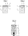
Die in Fig. 1 gezeigte, bekannte Hartstoffschneidleiste 1 besteht aus einem Träger 2, auf den das Hartstoffmesser 3 aufgelötet ist. Das Hartstoffmesser besteht aus dem Messerträger 4, auf den die Hartstoffschicht 5 aufgebracht ist. Der Hartstoff 5 ist bevorzugt polykristalliner Diamant (PKD) oder kubisches Bornitrid (CBN).The known hard
Die offenliegenden Flanken 6 des Messerträgers 4 sind bei der herkömmlichen Schneidleiste 1 (Fig. 1) der Abnützung ausgesetzt. Bereits nach kurzer Zeit wird hierdurch die Hartstoffschicht 5 unterhöhlt, was zu Schäden an der Schneidante führt. Wie Fig. 2 zeigt, kann dieses Problem erfindungsgemäss dadurch gelöst werden, dass das Messer 3 in eine V-förmige Nut im Träger 2 eingesetzt wird, wozu die Flanken 6 des Messerträgers 4 spiegelbildlich zur Form der Nut abgetragen werden. Die entstehenden Schrägen erstrecken sich dabei bevorzugt randlos bis zur Hartstoffschicht 5. Nach dem Einsetzen können die Seiten des Trägers 2 auf die Masse des Messers 3 abgeschliffen werden. Versuche ergaben, dass die Abrasion zunächst in einem Bereich etwas entfernt von der Schneidkante einsetzt, wo der hochverschleissfeste Träger 2 bereits eine grössere Wandstärke aufweist und damit über längere Zeit das Messer 3 vor der Unterhöhlung schützen kann. Aus demselben Befund heraus ist es auch nicht kritisch, wenn infolge von Herstellungstoleranzen ein geringfügiger Spalt zwischen der Hartstoffschicht und den seitlichen Oberkanten der V-Nut im Träger 2 besteht.The exposed flanks 6 of the
Die zweite Problemzone stellt die Lötverbindung 7 zwischen dem Messerträger 4 und dem Träger 2 dar. Der Messerträger 4 weist gemäss oben gesagtem einen Kohlenstoffüberschuss auf, der einerseits die mechanischen Eigenschaften des Trägermaterials 4 verschlechtert und andererseits auch die Lötfähigkeit mindert. Selbst oder gerade beim Einsetzen des Messers 3 in eine V-Nut wurde eine für die Praxis ungenügende Zuverlässigkeit der Verbindung zwischen Träger 2 und Messer 3 gefunden. Da bei der V-Nut die beim Schneiden auftretenden Kräfte in erhöhtem Masse in Scherbeanspruchungen umgewandelt werden, ist bei der V-Nut die Qualität der Verbindung zwischen Träger 2 und Messer 3 von gesteigerter Bedeutung.The second problem area is the
Es wurde überraschenderweise gefunden, dass sich die Oberfläche 7 des Messerträgers 4 bei hohen Temperaturen metallisieren und damit lötfreundlich gestalten lässt, bevorzugt gemäss dem Verfahren, wie es in der CH-649 098 beschrieben ist. Entgegen der Erwartung, dass die Hartstoffschicht bei den für die Metallisierung nötigen Temperaturen angegriffen und schlimmstenfalls zersetzt werde, wurden überraschend keine derartigen Auswirkungen in merklichem Umfang beobachtet, sofern die Metallisierung in inerter, zumindest sauerstofffreier Atmosphäre oder im Vakuum durchgeführt wird.It has surprisingly been found that the
Die damit erzielte, zuverlässige Lötverbindung erlaubt es, die Vorteile der V-Verbindung auszunutzen. Das erfindungsgemässe Messer erreicht hohe Standzeiten, da hochverschleissfeste Träger 2 verwendet werden können, und kann in hoher Ausbeute hergestellt werden. Das Risiko einer Ablösung des Messers vom Träger 2 im Betrieb ist durch die qualitativ hochwertige Lötverbindung auf einen unbedeutenden Wert gemindert. Vorteilhaft ist es auch, dass die erfindungsgemässe Schneidleiste zwei Schneidkanten aufweisen kann, wodurch sich die Einsatzdauer nochmals erhöht. Mit dem erfindungsgemässen Messer werden ohne weiteres Standzeiten von![]()
![]()
In einer Ausführung der Schneidleiste sind am Träger 2 Befestigungselemente, wie Löcher, eingesetzte Gewindebuchsen usw. vorhanden, um die Anordnung am Einsatzort zu befestigen. In einer bevorzugten Ausführung gemäss Fig. 3 wird die Schneidleiste 1 mit einem Halter 8 verbunden, der die obengenannten Befestigungselemente aufweist. Da der Halter 8 nicht mehr in dem Masse wie die Schneidleiste 1 Abrasionseffekten ausgesetzt ist, können ausser Hartmetall auch andere geeignete Materialien eingesetzt werden, wie z. B. Edelstahl, in dem sich die Befestigungselemente leichter anbringen lassen. Fig. 3 zeigt als Beispiel Querlöcher 12.In one embodiment of the cutting bar, two fastening elements, such as holes, inserted threaded bushings, etc., are present on the carrier in order to fasten the arrangement at the place of use. In a preferred embodiment according to FIG. 3, the cutting
Die Verbindung zwischen Halter 8 und Träger 2 wird bevorzugt lösbar ausgeführt, z. B. mittels Schraubelementen. Eine bevorzugte Lösung ist dabei, im Träger 2 mindestens eine Bohrung vorzusehen, in die eine Gewindestange 9 eingesetzt und unlösbar befestigt, z. B. verlötet wird. Im Halter 8 ist eine entsprechende Bohrung 10 vorgesehen, durch die die Gewindestange 9 ragt. An der dem Träger 2 gegenüberliegenden Seite des Halters 8 wird auf die Gewindestange 9 eine Mutter 11 aufgedreht und angezogen. Eine andere Ausführung verwendet statt der Gewindestange eine Schraube, die in eine im Träger 2 eingesetzte Gewindebuchse eingeschraubt wird.The connection between holder 8 and
Eine exakte Positionierung erfolgt, analog zur Verbindung Träger 2 / Hartstoffmesser 3, durch Anbringen einer Nut mit schrägen Flanken, also einer V-Nut, im Halter 2 und eine dazu komplementäre Ausführung der Verbindungsfläche des Halters 2. Auch hier kann die Nut etwas tiefer ausgeführt sein, um Toleranzen auszugleichen.Exact positioning takes place, analogous to the connection between
Bei dieser Ausführung ist es möglich, auf dem Halter 8 mehrere, kürzere Hartstoffmesser 1, 2 nebeneinander anzubringen, die jeweils einzeln ausgewechselt werden können. Diese Unterteilung ist einerseits nötig, da die gängigen Hartstoffmesser 1 nicht in beliebigen Längen verfügbar sind, die oft kleiner sind als die geforderte Länge der Schneidleiste 1. Als Beispiel sei eine Schneidleiste mit einer Länge von 350 mm angegeben, deren Schneidfläche sich aus sieben Hartstoffmessern von je 50 mm Länge zusammensetzt. Die Möglichkeit, die Hartstoffmesser separat austauschen zu können, oder durch Umdrehen, die zweite Schneidkante zum Einsatz bringen zu können, ist in Anbetracht des erheblichen Kostenfaktors dieser Teile ein wesentlicher Vorteil.In this embodiment, it is possible to mount several, shorter
In einer weiteren bevorzugten Ausführung gemäss den Figuren 4 und 5 ist in den Träger 4 in Längsrichtung des Hartstoffmessers 3 eine hinterschnittene Nut 15 eingearbeitet. In diese Nut 15 können Nutsteine 16 eingesetzt werden, in die ein Gewinde eingeschnitten ist. Wie Figur 4 zeigt, wird von unten durch eine Bohrung 18 im Träger 2 eine Schraube 17 hindurchgeführt und in einen Nutstein 16 eingeschraubt, wodurch das Hartstoffmesser 3 auf dem Träger 2 in der V-Nut fixiert wird. Für einen sicheren Sitz des Hartstoffmessers 3 auf dem Träger 2 ist es angesichts der hohen, schräg auf die Schneidkante der Hartstoffschicht 5 einwirkenden Kräfte besonders vorteilhaft, den Winkel α grösser als den Winkel β zu wählen (Fig. 5). Hierdurch wird ein Hineingleiten des Hartstoffmessers in den Spalt zwischen Nutstein 16 und Träger 2 sicher vermieden. Pro Hartstoffmesser werden bevorzugt mindestens 2 Nutsteine zur Befestigung vorgesehen. Die Bohrung 18 ist bevorzugt so ausgebildet, dass der Kopf der Schraube 17 im Träger versenkt ist. Durch Wahl der Tiefe dieser Versenkung kann auch eine Anpassung an die Länge der zur Verfügung stehenden Schrauben 17 erfolgen.In a further preferred embodiment according to FIGS. 4 and 5, an undercut
Die Nut 15 wird bevorzugt in dem Messerträger 4 mittels Erosion hergestellt. Dies geschieht einfacherweise in einem Arbeitsgang mit der Herstellung der schrägen Flanken des Messerträgers 4. Zusätzlich kann die Schneidleiste noch analog zur Ausführung gemäss Fig. 3 auf einem zusätzlichen Halter 8 angebracht werden.The
Änderungen sind im Rahmen der Erfindung leicht ersichtlich. Es ist möglich, für die Verbindungsflächen statt der V-Nutähnlichen Ausführung eine beliebige andere, versenkte Anordnung zu finden, z. B. in Form eines Kreisbogenabschnitts. Zu beachten ist dabei, dass die Wandstärke des Trägers im Bereich der primären Abrasionseffekte eine ausreichende Dicke erreicht. Für die Messer können auch beliebige andere Hartstoffschichten verwendet werden.Changes are readily apparent within the scope of the invention. It is possible to find any other recessed arrangement for the connecting surfaces instead of the V-groove-like design, e.g. B. in the form of a circular arc section. It should be noted that the wall thickness of the beam reaches a sufficient thickness in the area of the primary abrasion effects. Any other hard material layers can also be used for the knives.
Es ist auch denkbar, eine andere Verbindungsart zwischen Messer und Träger vorzusehen, wie z. B. Schweissen. Zur Erzielung grösserer Längen, als die verfügbaren Hartstoffmesser aufweisen, können auf einem Träger 2 mehrere Hartstoffmesser 3 nebeneinander angordnet werden, wie auch mehrere Träger 2 nebeneinander auf dem Halter 8. Zur Positionierung des Trägers 2 auf dem Halter 8 sind auch andere, bekannte Positionierungsmittel anwendbar, wie z. B. Positionierstifte.It is also conceivable to provide another type of connection between the knife and the carrier, such as. B. welding. To achieve greater lengths than the available hard material knives have, several
Für die Befestigung des Hartstoffmessers über Nutsteine gemäss Figg. 4 und 5 sind auch andere, lösbare oder nicht lösbare Verbindungstechniken denkbar, wie Nieten, an den Nutsteinen angebrachte Bolzen zum Verschrauben, Nieten, Schweissen, usw.For fastening the hard material knife using slot nuts as shown in Fig. 4 and 5, other, releasable or non-releasable connection techniques are also conceivable, such as rivets, bolts attached to the slot nuts for screwing, riveting, welding, etc.
Claims (18)
Applications Claiming Priority (2)
| Application Number | Priority Date | Filing Date | Title |
|---|---|---|---|
| CH332392 | 1992-10-26 | ||
| CH3323/92 | 1992-10-26 |
Publications (3)
| Publication Number | Publication Date |
|---|---|
| EP0595763A2 true EP0595763A2 (en) | 1994-05-04 |
| EP0595763A3 EP0595763A3 (en) | 1994-06-08 |
| EP0595763B1 EP0595763B1 (en) | 1996-08-14 |
Family
ID=4253494
Family Applications (1)
| Application Number | Title | Priority Date | Filing Date |
|---|---|---|---|
| EP93810641A Expired - Lifetime EP0595763B1 (en) | 1992-10-26 | 1993-09-09 | Cutter bar with a high wear resistance and method of making it |
Country Status (3)
| Country | Link |
|---|---|
| EP (1) | EP0595763B1 (en) |
| AT (1) | ATE141189T1 (en) |
| DE (1) | DE59303432D1 (en) |
Cited By (2)
| Publication number | Priority date | Publication date | Assignee | Title |
|---|---|---|---|---|
| AT513376B1 (en) * | 2012-11-12 | 2014-04-15 | Econ Gmbh | Granulating knife for a knife head of a granulating device |
| WO2015193249A1 (en) * | 2014-06-18 | 2015-12-23 | Betek Gmbh & Co. Kg | Shear bar |
Citations (5)
| Publication number | Priority date | Publication date | Assignee | Title |
|---|---|---|---|---|
| US2857111A (en) * | 1955-01-21 | 1958-10-21 | Unipulver Ltd | Rotor blades and blade mounting means for grinding mills |
| DE2137529A1 (en) * | 1971-07-27 | 1973-03-01 | Hench sen, Hans, 8754 Großostheim | Tool for crushing solid materials |
| DE3108954A1 (en) * | 1981-03-10 | 1982-09-23 | Michael Dr.-Ing. 3100 Celle Kaiser | Cutter |
| WO1991002622A1 (en) * | 1989-08-17 | 1991-03-07 | Schober Gmbh Werkzeug- Und Maschinenbau | Cutting roller or punching cylinder and process for manufacturing |
| EP0430872A2 (en) * | 1989-11-22 | 1991-06-05 | Balzers Aktiengesellschaft | Tool or instrument with a wear-resistant hard layer for working or processing of organic material |
-
1993
- 1993-09-09 AT AT93810641T patent/ATE141189T1/en active
- 1993-09-09 EP EP93810641A patent/EP0595763B1/en not_active Expired - Lifetime
- 1993-09-09 DE DE59303432T patent/DE59303432D1/en not_active Expired - Fee Related
Patent Citations (5)
| Publication number | Priority date | Publication date | Assignee | Title |
|---|---|---|---|---|
| US2857111A (en) * | 1955-01-21 | 1958-10-21 | Unipulver Ltd | Rotor blades and blade mounting means for grinding mills |
| DE2137529A1 (en) * | 1971-07-27 | 1973-03-01 | Hench sen, Hans, 8754 Großostheim | Tool for crushing solid materials |
| DE3108954A1 (en) * | 1981-03-10 | 1982-09-23 | Michael Dr.-Ing. 3100 Celle Kaiser | Cutter |
| WO1991002622A1 (en) * | 1989-08-17 | 1991-03-07 | Schober Gmbh Werkzeug- Und Maschinenbau | Cutting roller or punching cylinder and process for manufacturing |
| EP0430872A2 (en) * | 1989-11-22 | 1991-06-05 | Balzers Aktiengesellschaft | Tool or instrument with a wear-resistant hard layer for working or processing of organic material |
Cited By (4)
| Publication number | Priority date | Publication date | Assignee | Title |
|---|---|---|---|---|
| AT513376B1 (en) * | 2012-11-12 | 2014-04-15 | Econ Gmbh | Granulating knife for a knife head of a granulating device |
| AT513376A4 (en) * | 2012-11-12 | 2014-04-15 | Econ Gmbh | Granulating knife for a knife head of a granulating device |
| EP2730384B1 (en) | 2012-11-12 | 2016-09-28 | ECON GmbH | Cutter blade for a blade head of a granulating device |
| WO2015193249A1 (en) * | 2014-06-18 | 2015-12-23 | Betek Gmbh & Co. Kg | Shear bar |
Also Published As
| Publication number | Publication date |
|---|---|
| DE59303432D1 (en) | 1996-09-19 |
| EP0595763A3 (en) | 1994-06-08 |
| EP0595763B1 (en) | 1996-08-14 |
| ATE141189T1 (en) | 1996-08-15 |
Similar Documents
| Publication | Publication Date | Title |
|---|---|---|
| DE69406046T2 (en) | Saw chain cutting link | |
| DE68918369T2 (en) | Drill bits with cement carbide inserts. | |
| DE19903037C2 (en) | Cutting tool with means for chip control | |
| EP0715055B1 (en) | A tool with a holder and cutting element | |
| EP0625400A1 (en) | Tool for the formation of an internal thread | |
| DE2848976A1 (en) | DEVICE FOR MACHINE TREATMENT OF THE SURFACE OF LONG WOODS | |
| EP0375707A1 (en) | Tool arrangement for ultrasonic welding. | |
| EP1023961B1 (en) | Cutting tool | |
| AT9431U1 (en) | CUTTING BOARD | |
| DE69503537T2 (en) | CVD diamond cutting tools | |
| DE19625509A1 (en) | Tool component | |
| EP0595763B1 (en) | Cutter bar with a high wear resistance and method of making it | |
| EP2039482B1 (en) | Segment knife | |
| EP0099004A1 (en) | Cutting die, in particular for contour-cutting, and a method of manufacturing it | |
| DE68917342T2 (en) | Tools with insert teeth. | |
| DE102019117799B4 (en) | Cutting tool with asymmetrical teeth with cutting particles | |
| DE3108954A1 (en) | Cutter | |
| EP0715919A1 (en) | Method and saw blade for sawing steel workpieces | |
| DE925142C (en) | Cutting tool | |
| DE69610729T2 (en) | Cutting insert for milling drill bits | |
| DE19929477A1 (en) | Cutting knife has facet facing flank, basic body to which is fixed cutting strip with cutting section and edge, insertion end, groove and thrust piece | |
| AT505198B1 (en) | CUTTING TOOL | |
| DE3531767C2 (en) | ||
| EP0947268B1 (en) | Cutting insert for machining tools | |
| DE1477299A1 (en) | Cutting tool for working metal |
Legal Events
| Date | Code | Title | Description |
|---|---|---|---|
| PUAI | Public reference made under article 153(3) epc to a published international application that has entered the european phase |
Free format text: ORIGINAL CODE: 0009012 |
|
| PUAL | Search report despatched |
Free format text: ORIGINAL CODE: 0009013 |
|
| AK | Designated contracting states |
Kind code of ref document: A2 Designated state(s): AT BE CH DE DK ES FR GB GR IE IT LI LU MC NL PT SE |
|
| AK | Designated contracting states |
Kind code of ref document: A3 Designated state(s): AT BE CH DE DK ES FR GB GR IE IT LI LU MC NL PT SE |
|
| RBV | Designated contracting states (corrected) |
Designated state(s): AT CH DE FR GB LI NL |
|
| 17P | Request for examination filed |
Effective date: 19940722 |
|
| GRAG | Despatch of communication of intention to grant |
Free format text: ORIGINAL CODE: EPIDOS AGRA |
|
| GRAH | Despatch of communication of intention to grant a patent |
Free format text: ORIGINAL CODE: EPIDOS IGRA |
|
| 17Q | First examination report despatched |
Effective date: 19960214 |
|
| GRAH | Despatch of communication of intention to grant a patent |
Free format text: ORIGINAL CODE: EPIDOS IGRA |
|
| GRAA | (expected) grant |
Free format text: ORIGINAL CODE: 0009210 |
|
| AK | Designated contracting states |
Kind code of ref document: B1 Designated state(s): AT CH DE FR GB LI NL |
|
| PG25 | Lapsed in a contracting state [announced via postgrant information from national office to epo] |
Ref country code: GB Effective date: 19960814 Ref country code: FR Effective date: 19960814 |
|
| REF | Corresponds to: |
Ref document number: 141189 Country of ref document: AT Date of ref document: 19960815 Kind code of ref document: T |
|
| REG | Reference to a national code |
Ref country code: CH Ref legal event code: NV Representative=s name: AMMANN PATENTANWAELTE AG BERN |
|
| PG25 | Lapsed in a contracting state [announced via postgrant information from national office to epo] |
Ref country code: AT Effective date: 19960909 |
|
| REF | Corresponds to: |
Ref document number: 59303432 Country of ref document: DE Date of ref document: 19960919 |
|
| EN | Fr: translation not filed | ||
| GBV | Gb: ep patent (uk) treated as always having been void in accordance with gb section 77(7)/1977 [no translation filed] |
Effective date: 19960814 |
|
| PLBE | No opposition filed within time limit |
Free format text: ORIGINAL CODE: 0009261 |
|
| STAA | Information on the status of an ep patent application or granted ep patent |
Free format text: STATUS: NO OPPOSITION FILED WITHIN TIME LIMIT |
|
| 26N | No opposition filed | ||
| PGFP | Annual fee paid to national office [announced via postgrant information from national office to epo] |
Ref country code: CH Payment date: 19970924 Year of fee payment: 5 |
|
| PGFP | Annual fee paid to national office [announced via postgrant information from national office to epo] |
Ref country code: NL Payment date: 19970930 Year of fee payment: 5 |
|
| PGFP | Annual fee paid to national office [announced via postgrant information from national office to epo] |
Ref country code: DE Payment date: 19971119 Year of fee payment: 5 |
|
| PG25 | Lapsed in a contracting state [announced via postgrant information from national office to epo] |
Ref country code: LI Free format text: LAPSE BECAUSE OF NON-PAYMENT OF DUE FEES Effective date: 19980930 Ref country code: CH Free format text: LAPSE BECAUSE OF NON-PAYMENT OF DUE FEES Effective date: 19980930 |
|
| PG25 | Lapsed in a contracting state [announced via postgrant information from national office to epo] |
Ref country code: NL Free format text: LAPSE BECAUSE OF NON-PAYMENT OF DUE FEES Effective date: 19990401 |
|
| REG | Reference to a national code |
Ref country code: CH Ref legal event code: PL |
|
| NLV4 | Nl: lapsed or anulled due to non-payment of the annual fee |
Effective date: 19990401 |
|
| PG25 | Lapsed in a contracting state [announced via postgrant information from national office to epo] |
Ref country code: DE Free format text: LAPSE BECAUSE OF NON-PAYMENT OF DUE FEES Effective date: 19990701 |