EP0595751B1 - Verfahren zur Leitweglenkung von elektronischen Nachrichten - Google Patents
Verfahren zur Leitweglenkung von elektronischen Nachrichten Download PDFInfo
- Publication number
- EP0595751B1 EP0595751B1 EP93480145A EP93480145A EP0595751B1 EP 0595751 B1 EP0595751 B1 EP 0595751B1 EP 93480145 A EP93480145 A EP 93480145A EP 93480145 A EP93480145 A EP 93480145A EP 0595751 B1 EP0595751 B1 EP 0595751B1
- Authority
- EP
- European Patent Office
- Prior art keywords
- switch
- candidate
- path
- station
- weight
- Prior art date
- Legal status (The legal status is an assumption and is not a legal conclusion. Google has not performed a legal analysis and makes no representation as to the accuracy of the status listed.)
- Expired - Lifetime
Links
- 238000000034 method Methods 0.000 title claims description 33
- 101000710013 Homo sapiens Reversion-inducing cysteine-rich protein with Kazal motifs Proteins 0.000 description 21
- 101000911772 Homo sapiens Hsc70-interacting protein Proteins 0.000 description 12
- 101001139126 Homo sapiens Krueppel-like factor 6 Proteins 0.000 description 12
- 101000661807 Homo sapiens Suppressor of tumorigenicity 14 protein Proteins 0.000 description 12
- 230000000295 complement effect Effects 0.000 description 5
- 238000010586 diagram Methods 0.000 description 5
- 230000007423 decrease Effects 0.000 description 1
- 238000007689 inspection Methods 0.000 description 1
- 230000001172 regenerating effect Effects 0.000 description 1
Images


Classifications
-
- H—ELECTRICITY
- H04—ELECTRIC COMMUNICATION TECHNIQUE
- H04L—TRANSMISSION OF DIGITAL INFORMATION, e.g. TELEGRAPHIC COMMUNICATION
- H04L45/00—Routing or path finding of packets in data switching networks
-
- H—ELECTRICITY
- H04—ELECTRIC COMMUNICATION TECHNIQUE
- H04L—TRANSMISSION OF DIGITAL INFORMATION, e.g. TELEGRAPHIC COMMUNICATION
- H04L45/00—Routing or path finding of packets in data switching networks
- H04L45/12—Shortest path evaluation
Definitions
- multiple paths may exist for sending an electronic message from a given source station to a selected destination station.
- the paths will have a variety of lengths. For a given length, there may be one or more different paths between the source processor and the destination processor having that length.
- the step of generating the series of route signals comprises the step of storing a weight w m / o for each switch link connecting an output port 0 m of a switch m to an input port of another switch.
- One or more candidate paths through the switch network starting at the source station and ending at initial candidate destinations are identified.
- Each initial candidate destination comprises a switch or a station having an input port directly connected to an output port of a switch having an input port directly connected to the source station. If one or more candidate destinations are the destination station, a candidate path ending at the destination station is selected, and a series of route signals corresponding to the selected candidate path is generated.
- Each next candidate destination comprises a switch or a station having an input port directly connected to an output port of a prior candidate destination.
- Each extended candidate path has a path weight comprising the weights of switch links along the candidate path.
- next candidate destinations are the destination station
- a candidate path ending at the destination station and having a path weight better than or equal to the path weight of each other candidate path ending at the destination station is selected.
- a series of route signals corresponding to the selected candidate path is generated. If none of the candidate destinations are the destination station, the candidate paths are further extended in the manner described above until one or more candidate destinations are the destination station.
- the step of generating a series of route signals corresponding to the selected candidate path may comprise generating a series of route signals identifying switch output ports connected to the links forming the candidate path.
- the path weight of a first candidate path is better than the path weight of a second candidate path if the weight of the switch link of the first candidate path connected to an output of the common branch switch for the first and second candidate paths is less than the weight of the switch link of the second candidate path connected to an output of the common branch switch for the first and second candidate paths.
- the series of route signals may be stored in a route table.
- the message may then be generated by reading the series of route signals from the route table.
- the method according to the present invention may further comprise the step of disabling the read route signal.
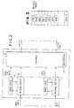
- Figure 1 is a block diagram of an example of a communication network for use in the method of sending electronic messages according to the invention.
- Figure 3 schematically shows an example of an electronic message for use in the method according to the present invention.
- FIG. 1 is a block diagram of an example of a communication network for use in the method of sending messages according to the invention.
- stations ST0 through ST15 represent both source stations for generating electronic messages and destination stations for receiving electronic messages.
- the stations ST0 through ST15 may be, for example, computer processor nodes containing computer processors, communication circuits for sending and receiving electronic messages, and any necessary adapters between the computer processors and the communication circuits.
- each of switches A through D has an output port connected to an input port of each of switches E through H by way of a switch link.
- Each of switches A through D have an input port connected to an output port of each of switches E through H by way of different switch links. Consequently, each line connecting one of switches A through D with one of switches E through H schematically represents two switch links forming a full duplex communication channel.
- An electronic message may be sent from a source station ST0 to ST15 through the network of switches A to H and links to a destination station ST0 to ST15 by generating a series of one or more route signals.
- Each route signal identifies an output port of a switch in the network of switches.
- An electronic message contains the series of route signals. The message is sequentially sent to each of a series of one or more switches. Each switch reads a route signal in the message and sends the message to a switch or a station having an input port connected to an output port identified by the route signal.
- Figure 3 schematically shows an example of an electronic message for use in the method according to the invention.
- message packets may have variable lengths up to 255 bytes of eight binary digits (bits) per byte.
- the first byte of the packet contains the message length. Any number of following bytes in the packet contain route information.
- the message data follows the route information in the packet.
- the message packet has four route bytes and N data bytes.
- the series of route signals is generated, according to the present invention, by storing a weight w m / o for each switch link connecting an output port 0 m of a switch m to an input port of another switch.
- Table 2 shows an example of initial switch link weights.
- each switch link is identified by the switch output port to which it is connected.
- the switch link connecting switch A to switch E is identified by its connection to output port 4 of switch A.
- the switch link connecting switch A to F is identified by its connection to output port 5 of switch A.
- the remaining switch links shown in Figure 1 are similarly identified.
- Each initial candidate destination comprises a switch or a station having an input port directly connected to an output port of a switch having an input port directly connected to the source station.
- Table 3 shows initial candidate paths starting at source station ST0 for the hypothetical communication network shown in Figure 1.
- INITIAL CANDIDATE PATHS Initial Candidate Path Source Station Link (weight) Candidate Destination Total Path Weight ST0 A0 ST0 0 ST0 A1 ST1 0 ST0 A2 ST2 0 ST0 A3 ST3 0 ST0 A4 (0) E 0 ST0 A5 (0) F 0 ST0 A6 (0) G 0 ST0 A7 (0) H 0
- Table 4 shows first extended candidate paths for the communication network shown in Figure 1.
- the source station remains station ST0.
- the next candidate destinations are switches A, B, C, and D, each having an input port directly connected to an output port of prior candidate destination switches E, F, G, and H. Since the prior candidate destinations stations ST0, ST1, ST2, and ST3 are not switches, extended candidate paths are normally not obtained from these prior candidate destinations.
- Each extended candidate path of Table 4 has a path weight comprising the weights of switch links along the candidate path.
- the path weight for the extended candidate path A4/E1 comprises the weight of the switch link A4 (connecting output port A4 to input port E0).
- a candidate path ending at the destination station and having a path weight which is better than or equal to the path weight of each other candidate path ending at the destination station is selected.
- a series of route signals corresponding to the selected candidate path is generated. Otherwise, the candidate paths are further extended in the manner described above.
- Table 4 shows second extended candidate paths for the communication network shown in Figure 1.
- SECOND EXTENDED CANDIDATE PATHS Second Extended Candidate Paths Source Station Link (weight) Link (weight) Link (weight) Candidate Destination Total Path Weight ST0 A0 NONE NONE NONE 0 ST0 A1 NONE NONE NONE 0 ST0 A2 NONE NONE NONE 0 ST0 A3 NONE NONE NONE 0 ST0 A4 (0) E0 (0) A0 ST0 0 ST0 A4 (0) E0 (0) A1 ST1 0 ST0 A4 (0) E0 (0) A2 ST2 0 ST0 A4 (0) E0 (0) A3 ST3 0 ST0 A4 (0) E0 (0) E0 (0) E 0 (0) A5 (0) F 0 ST0 A4 (0) E0 (0) A6 (0) G 0 ST0 A4 (0) E0 (0) A7
- the source station remains station ST0.
- the next candidate destinations are switches E, F, G, and H, and stations ST0 through ST15.
- Each next candidate destination switch or station has an input port directly connected to an output port of the prior candidate destinations shown in Table 4.
- Each extended candidate path of Table 5 has a path weight comprising the weights of the switch links along the candidate path.
- the path weight for the extended candidate path A4/E1/B0 comprises the weight of the switch link A4 (connecting output port A4 to input port E0), and the weight of the switch link E1 (connecting output port E1 to input port B4).
- each pair of extended candidate paths contain a common root path extending from the source station to a common branch switch from which the paths diverge.
- the path weight of a first candidate path is better than the path weight of a second candidate path if the weight of the switch link of the first candidate path connected to an output of the common branch switch for the first and second candidate paths is better than (for example, less than) the weight of the switch link of the second candidate path connected to an output of the common branch switch for the first and second candidate paths.
- the common root path extends from the source station ST0 to the branch switch A.
- the common root path extends from the source station ST0 to the branch switch A.
- the candidate path A4/E1/B0 is again selected, and a series of route signals corresponding to the selected candidate path A4/E1/B0 is generated.
- the step of selecting a candidate path ending at the destination station may further comprise changing the weight w m / o of each switch link forming the selected candidate path.
- the step of changing the weights of the switch links forming the selected candidate path may comprise increasing the weight of each switch link forming the selected candidate path by a constant K'.
- K' may be equal to + 1.
- Table 6 shows a hypothetical example of revised switch link weights obtained after selecting the path A4/E1/B0 for source station ST0 and for destination station ST4.
- Table 7 shows the second extended candidate paths for destination stations ST5 through ST15 with revised path weights according to Table 6.
- SECOND EXTENDED CANDIDATE PATHS WITH REVISED WEIGHTS Second Extended Candidate Paths Source Station Link (weight) Link (weight) Link (weight) Candidate Destination Total Path Weight ST0 A0 NONE NONE NONE 0 ST0 A1 NONE NONE NONE 0 ST0 A2 NONE NONE NONE 0 ST0 A3 NONE NONE NONE 0 ST0 A4 (1) EO (0) A0 ST0 1 ST0 A4 (1) E0 (0) A1 ST1 1 ST0 A4 (1) E0 (0) A2 ST2 1 ST0 A4 (1) E0 (0) A3 ST3 1 ST0 A4 (1) E0 (0) A4 (1) E0 (0) A5 (0) F 1 ST0 A4 (1) E0 (0) A6 (0) G 1 ST0 A4 (1) E0 (0) A
- each extended candidate path has a path weight comprising the weights of the switch links along the candidate path.
- the common root path extends from the source station ST0 to the branch switch A.
- the common root path extends from the source station ST0 to the branch switch A.
- the common root path extends from the source station ST0 to the branch switch A.
- the candidate path AS/F1/B1 is again selected, and a series of route signals corresponding to the selected candidate path A5/F1/B1 is generated.
- each extended candidate path could have a path weight comprising the sum of the weights of the switch links along the candidate path.
- the path weight of path A4/E1/B1 would be the sum of the weights of switch link A4 and switch link E1 resulting in a path weight of 2.
- the weights of paths A5/F1/B1, A6/G1/B1, and A7/H1/B1 in this alternative would be zero.
- candidate paths in an order from best to worst.
- the candidate path to that destination station is selected, and a corresponding series of route signals is generated.
- the method of generating the series of route signals according to the present invention may further comprise storing the series of route signals in a route table, and generating the electronic message by reading the series of route signals from the route table.
- the route table contains a route signal for each source station and each destination station. Each route signal identifies switch output ports connected to the links in the communication network which form the selected path. Table 8 shows the selected paths for routes from source station ST0 to destination stations STI, ST2, ST3, ST4, and ST5, which were obtained in the manner described above.
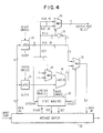
- the lower order route field bits R ⁇ 2..0 ⁇ in latch 32 are provided to the "true" (1) input of a multiplexer 34.
- the higher order route field bits R ⁇ 6..4 ⁇ in latch 32 are provided to the "complement” (0) input of multiplexer 34.
- the route field selector bit R ⁇ 7 ⁇ is provided to the control input of multiplexer 34.
- route field selector bit R ⁇ 7 ⁇ is "0"
- the higher order route field bits select the switch output port. If the route field selector bit R ⁇ 7 ⁇ is "1", the lower order route field bits select the switch output port.
- route field selector bit R ⁇ 7 ⁇ is inverted by inverter 36, is recombined with route bits R ⁇ 6..0 ⁇ , and the modified route byte is provided to the "complement" (0) input to multiplexer 38.
- the length byte in latch 30 is provided to one input of an adder 40.
- the route field selector bit R ⁇ 7 ⁇ is provided to the control input of a multiplexer 42 having an input signal of 0 at its "complement” (0) input, and having an input signal of -1 at its "true” (1) input.
- the output of multiplexer 42 is provided to the other input of adder 40. If the route field selector bit is "0”, the output of adder 40 is the original length byte. If the route field selector bit is "1", the output of adder 40 is the original length byte minus 1.
- the route field selector bit R ⁇ 7 ⁇ is provided to a "Discard" input to state machine 28. If the route field selector bit R ⁇ 7 ⁇ is "1", the state machine provides a SELECT signal to multiplexer 38 choosing the "true” input, and provides a "put” signal to message buffer 22, thereby storing the reduced length byte back in the message buffer. If the route field selector bit R ⁇ 7 ⁇ is "0", the state machine first provides a SELECT (select complement) signal to multiplexer 38 choosing the "complement” input, and provides a "put” signal to message buffer 22, thereby storing the modified route byte back in the message buffer in front of the message. The state machine then provides a SELECT signal to multiplexer 38 choosing the "true” input, and provides a "put” signal to message buffer 22, thereby storing the original length byte back in the message buffer in front of the modified route byte.
- Figure 5 shows the state diagram for the state machine 28 for the route logic circuit of Figure 4.
- the switch link weight for A4 indicates that A4 has been used 12 times to reach destination stations from source ST0, as it can also be seen in Table 10.
- the switch link weight for E1 indicates that E1 has been used 4 times, namely to reach destination stations ST4, ST5, ST6, and ST7.
Landscapes
- Engineering & Computer Science (AREA)
- Computer Networks & Wireless Communication (AREA)
- Signal Processing (AREA)
- Data Exchanges In Wide-Area Networks (AREA)
- Multi Processors (AREA)
- Computer And Data Communications (AREA)
- Small-Scale Networks (AREA)
Claims (16)
- Verfahren zum Senden einer elektronischen Nachricht von einer Quellenstation über ein Netzwerk aus einer Vielzahl von Vermittlungsstellen und Verbindungen an eine Bestimmungsstation, wobei das Verfahren umfaßt:dadurch gekennzeichnet, daß der Schritt des Erzeugens der Serie von Leitwegsignalen die Schritte umfaßt:Erzeugen einer Reihe von einem oder mehreren Leitwegsignalen, wobei jedes Leitwegsignal einen Ausgabeanschluß einer Vermittlungsstelle in dem Vermittlungsstellennetzwerk kennzeichnet;Erzeugen einer elektronischen Nachricht, welche die Reihe von Leitwegsignalen umfaßt; undsequentielles Senden der Nachricht an jeden einer Reihe von ein oder mehreren Vermittlungsstellen, wobei jede Vermittlungsstelle ein Leitwegsignal in der Nachricht liest und die Nachricht an eine Vermittlungsstelle oder eine Station sendet, die einen Eingabeanschluß haben, der mit einem durch das Leitwegsignal gekennzeichneten Ausgabeanschluß verbunden ist;(a) Speichern einer Gewichtung wo m für jede Vermittlungsstellenverbindung, die einen Ausgabeanschluß om einer Vermittlungsstelle m mit einem Eingabeanschluß einer anderen Vermittlungsstelle verbindet;(b) Kennzeichnen eines oder mehrerer Kandidatenwege durch das Vermittlungsstellennetzwerk, beginnend an der Quellenstation und endend bei anfänglichen Kandidatenbestimmungsorten, wobei jeder anfängliche Kandidatenbestimmungsort eine Vermittlungsstelle oder eine Station umfaßt, die einen Eingabeanschluß haben, der direkt mit einen Ausgabeanschluß einer Vermittlungsstelle verbunden ist, die einen Eingabeanschluß hat, der direkt mit der Quellenstation verbunden ist;(c) falls ein oder mehrere Kandidatenbestimmungsorte die Bestimmungsstation sind, Auswählen eines Kandidatenweges, der an der Bestimmungsstation endet, und Erzeugen einer Reihe von Leitwegsignalen, die dem ausgewählten Kandidatenweg entsprechen; andernfalls(d) falls die Bestimmungsstation kein Kandidatenbestimmungsort ist, Kennzeichnen eines oder mehrerer erweiterter Kandidatenwege durch das Vermittlungsstellennetzwerk, beginnend bei der Quellenstation und endend bei den nächsten Kandidatenbestimmungsorten, wobei jeder nächste Kandidatenbestimmungsort eine Vermittlungsstelle oder eine Station umfaßt, die einen Eingabeanschluß haben, der direkt mit einem Ausgabeanschluß eines früheren Kandidatenbestimmungsortes verbunden ist, wobei jeder erweiterte Kandidatenweg eine Weggewichtung hat, welche die Gewichtungen von Vermittlungsstellenverbindungen entlang des Kandidatenweges umfaßt; und dann(e) falls ein oder mehrere Kandidatenbestimmungsorte die Bestimmungsstation sind, Auswählen eines Kandidatenweges, der an der Bestimmungsstation endet und eine Weggewichtung hat, die besser oder gleich der Weggewichtung jedes anderen Kandidatenweges ist, der an der Bestimmungsstation endet, und Erzeugen einer Reihe von Leitwegsignalen, die dem ausgewählten Kandidatenweg entsprechen; andernfalls(f) Rückkehr zu Schritt (d).
- Verfahren, wie es in Anspruch 1 beansprucht wird, dadurch gekennzeichnet, daß jeder Kandidatenweg umfaßt:eine Reihe von einer oder mehreren Vermittlungsstellen, beginnend mit der Vermittlungsstelle, die einen direkt mit der Quellenstation verbundenen Eingabeanschluß hat, und endend mit einer Vermittlungsstelle, die einen direkt mit dem Kandidatenbestiininungsort des Kandidatenweges verbundenen Ausgabeanschluß hat;eine Stationsverbindung, welche die Quellenstation mit einem Eingabeanschluß der Anfangsvermittlungsstelle verbindet; undeine Stationsverbindung, die den Ausgabeanschluß der Endvermittlungsstelle mit der Bestimmungsstation verbindet.
- Verfahren, wie es in Anspruch 2 beansprucht wird, dadurch gekennzeichnet, daß jeder erweiterte Kandidatenweg weiterhin eine oder mehrere Vermittlungsstellenverbindungen umfaßt, die einen Ausgabeanschluß einer Vermittlungsstelle auf dem Wege mit einem Eingabeanschluß einer anderen Vermittlungsstelle auf dem Wege verbinden.
- Verfahren, wie es in einem beliebigen der vorhergehenden Ansprüche beansprucht wird, dadurch gekennzeichnet, daßjedes Paar von erweiterten Kandidatenwegen einen gemeinsamen Wurzelweg enthält, der sich von der Quellenstation zu einer gemeinsamen Verzweigungsvermittlungsstelle erstreckt, von dem aus die Wege auseinandergehen;die Weggewichtung eines ersten Kandidatenweges besser ist als die Weggewichtung eines zweiten Kandidatenweges, falls die Gewichtung der Vermittlungsstellenverbindung des ersten Kandidatenweges, der mit einer Ausgabe der Vermittlungsstelle auf dem gemeinsamen Zweig für den ersten und den zweiten Kandidatenweg verbunden ist, besser ist als die Gewichtung der Vermittlungsstellenverbindung des zweiten Kandidatenweges, der mit einer Ausgabe der Vermittlungsstelle auf dem gemeinsamen Zweig für den ersten und den zweiten Kandidatenweg verbunden ist.
- Verfahren, wie es in einem beliebigen der vorhergehenden Ansprüche beansprucht wird, dadurch gekennzeichnet, daß der Schritt des Erzeugens einer Reihe von Leitwegsignalen, die dem ausgewählten Kandidatenweg entsprechen, das Erzeugen einer Reihe von Leitwegsignalen umfaßt, die Vermittlungsstellenausgabeanschlüsse kennzeichnen, die an die Verbindungen angeschlossen sind, die den ausgewählten Kandidatenweg bilden.
- Verfahren, wie es in einem beliebigen der vorhergehenden Ansprüche beansprucht wird, dadurch gekennzeichnet, daß der Schritt des Speicherns von Gewichtungen für die Vermittlungsstellenverbindungen das Speichern eines Anfangswertes K für die Gewichtung wo m für jede Vermittlungsstellenverbindung umfaßt, die mit einem Ausgabeanschluß om einer Vermittlungsstelle m verbunden ist, wobei K eine ausgewählte Konstante ist.
- Verfahren, wie es in einem beliebigen der vorhergehenden Ansprüche beansprucht wird, dadurch gekennzeichnet, daß der Schritt des Auswählens eines an der Bestimmungsstation endenden Kandidatenweges weiterhin das Verändern der Gewichtung wo m jeder Vermittlungsstellenverbindung umfaßt, die den ausgewählten Kandidatenweg bildet.
- Verfahren, wie es in einem beliebigen der vorhergehenden Ansprüche beansprucht wird, dadurch gekennzeichnet, daß der Schritt des Veränderns der Gewichtungen der Vermittlungsstellenverbindungen, die den ausgewählten Kandidatenweg bilden, das Erhöhen der Gewichtung um eine Konstante K' bei jeder Vermittlungsstellenverbindung umfaßt, die den ausgewählten Kandidatenweg bildet.
- Verfahren, wie es in einem beliebigen der vorhergehenden Ansprüche beansprucht wird, dadurch gekennzeichnet, daß K = 0 und K' = +1 sind.
- Verfahren, wie es in Anspruch 9 beansprucht wird, dadurch gekennzeichnet, daß die Weggewichtung eines ersten Kandidatenweges besser als die Weggewichtung eines zweiten Kandidatenweges ist, falls die Gewichtung der Vermittlungsstellenverbindung des ersten Kandidatenweges, der mit einer Ausgabe der Vermittlungsstelle auf dem gemeinsamen Zweig für den ersten und den zweiten Kandidatenweg verbunden ist, geringer ist als die Gewichtung der Vermittlungsstellenverbindung des zweiten Kandidatenweges, der mit einer Ausgabe der Vermittlungsstelle auf dem gemeinsamen Zweig für den ersten und den zweiten Kandidatenweg verbunden ist.
- Verfahren, wie es in einem beliebigen der vorhergehenden Ansprüche beansprucht wird, das weiterhin die Schritte umfaßt:Speichern der Reihe von Leitwegsignalen in einer Leitwegtabelle; undErzeugen der Nachricht durch Lesen der Reihe von Leitwegsignalen aus der Leitwegtabelle.
- Verfahren, wie es in einem beliebigen der vorhergehenden Ansprüche beansprucht wird, dadurch gekennzeichnet, daß:die Bestimmungsstation einen Eingabeanschluß hat; unddas letzte Leitwegsignal in der Reihe von Leitwegsignalen in der Nachricht einen direkt mit dem Eingabeanschluß der Bestiminungsstation verbundenen Vermittlungsstellenausgabeanschluß kennzeichnet.
- Verfahren, wie es in einem beliebigen der vorhergehenden Ansprüche beansprucht wird, dadurch gekennzeichnet, daß der Schritt des sequentiellen Sendens der Nachricht die Schritte umfaßt:(1) Senden der Nachricht an eine erste Vermittlungsstelle, die einen direkt mit der Quellenstation verbunden Eingabeanschluß hat, wobei die erste Vermittlungsstelle mindestens zwei Ausgabeanschlüsse hat;(2) Lesen eines Leitwegsignals in der Nachricht, wobei das Leitwegsignal einen Ausgabeanschluß der ersten Vermittlungsstelle kennzeichnet; und(3) Senden der Nachricht an eine zweite Vermittlungsstelle, die eine direkt mit dem Ausgabeanschluß der ersten, durch das Leitwegsignal gekennzeichnete Vermittlungsstelle verbundenen Eingabeanschluß hat.
- Verfahren, wie es in einem beliebigen der vorhergehenden Ansprüche beansprucht wird, das weiterhin den Schritt des Deaktivierens des Leitwegsignals in der Nachricht umfaßt, nachdem das Leitwegsignal gelesen wurde.
- Verfahren, wie es in einem beliebigen der vorhergehenden Ansprüche beansprucht wird, dadurch gekennzeichnet, daß jeder erweiterte Kandidatenweg eine Weggewichtung hat, welche die Summe der Gewichtungen der Vermittlungsstellenverbindung entlang des Kandidatenweges umfaßt.
- Verfahren, wie es in einem beliebigen der vorhergehenden Ansprüche beansprucht wird, dadurch gekennzeichnet, daß es dafür benutzt wird, einen Übertragungsleitweg von einer Quellenstation über ein Netzwerk aus einer Vielzahl von Vermittlungsstellen und Verbindungen zu einer Bestimmungsstation zuzuordnen.
Applications Claiming Priority (2)
| Application Number | Priority Date | Filing Date | Title |
|---|---|---|---|
| US07/969,690 US5355364A (en) | 1992-10-30 | 1992-10-30 | Method of routing electronic messages |
| US969690 | 1992-10-30 |
Publications (3)
| Publication Number | Publication Date |
|---|---|
| EP0595751A2 EP0595751A2 (de) | 1994-05-04 |
| EP0595751A3 EP0595751A3 (en) | 1994-08-10 |
| EP0595751B1 true EP0595751B1 (de) | 1998-06-03 |
Family
ID=25515864
Family Applications (1)
| Application Number | Title | Priority Date | Filing Date |
|---|---|---|---|
| EP93480145A Expired - Lifetime EP0595751B1 (de) | 1992-10-30 | 1993-09-21 | Verfahren zur Leitweglenkung von elektronischen Nachrichten |
Country Status (5)
| Country | Link |
|---|---|
| US (1) | US5355364A (de) |
| EP (1) | EP0595751B1 (de) |
| JP (1) | JP3033927B2 (de) |
| CA (1) | CA2099412C (de) |
| DE (1) | DE69318928T2 (de) |
Families Citing this family (42)
| Publication number | Priority date | Publication date | Assignee | Title |
|---|---|---|---|---|
| US5617547A (en) * | 1991-03-29 | 1997-04-01 | International Business Machines Corporation | Switch network extension of bus architecture |
| US5694546A (en) | 1994-05-31 | 1997-12-02 | Reisman; Richard R. | System for automatic unattended electronic information transport between a server and a client by a vendor provided transport software with a manifest list |
| US6002455A (en) * | 1994-08-12 | 1999-12-14 | Sony Corporation | Digital data transfer apparatus using packets with start and end synchronization code portions and a payload portion |
| WO1996005677A1 (fr) * | 1994-08-12 | 1996-02-22 | Sony Corporation | Appareil de transfert de donnees numeriques |
| US5721820A (en) * | 1995-09-11 | 1998-02-24 | International Business Machines Corporation | System for adaptively routing data in switching network wherein source node generates routing message identifying one or more routes form switch selects |
| US5629930A (en) * | 1995-10-31 | 1997-05-13 | Northern Telecom Limited | Call routing in an ATM switching network |
| US5689644A (en) * | 1996-03-25 | 1997-11-18 | I-Cube, Inc. | Network switch with arbitration sytem |
| US6279826B1 (en) | 1996-11-29 | 2001-08-28 | Diebold, Incorporated | Fault monitoring and notification system for automated banking |
| US6768975B1 (en) | 1996-11-29 | 2004-07-27 | Diebold, Incorporated | Method for simulating operation of an automated banking machine system |
| US5984178A (en) * | 1996-11-29 | 1999-11-16 | Diebold, Incorporated | Fault monitoring and notification system for automated banking machines |
| US7161937B1 (en) * | 1996-12-13 | 2007-01-09 | Intel Corporation | Method and apparatus for routing encoded signals through a network |
| US5974467A (en) * | 1997-08-29 | 1999-10-26 | Extreme Networks | Protocol for communicating data between packet forwarding devices via an intermediate network interconnect device |
| US6023471A (en) * | 1997-10-07 | 2000-02-08 | Extreme Networks | Network interconnect device and protocol for communicating data among packet forwarding devices |
| US7082458B1 (en) | 2001-08-01 | 2006-07-25 | Luigi Guadagno | Dialog facilitation system for generating contextual order-preserving dialog postings and posting summaries from electronic messages |
| US7110389B2 (en) * | 2001-11-19 | 2006-09-19 | International Business Machines Corporation | Fanning route generation technique for multi-path networks |
| US10489449B2 (en) | 2002-05-23 | 2019-11-26 | Gula Consulting Limited Liability Company | Computer accepting voice input and/or generating audible output |
| US8611919B2 (en) | 2002-05-23 | 2013-12-17 | Wounder Gmbh., Llc | System, method, and computer program product for providing location based services and mobile e-commerce |
| US7366092B2 (en) * | 2003-10-14 | 2008-04-29 | Broadcom Corporation | Hash and route hardware with parallel routing scheme |
| US7313095B1 (en) | 2003-11-06 | 2007-12-25 | Sprint Communications Company L.P. | Method for estimating telecommunication network traffic using link weight changes |
| US7313629B1 (en) * | 2003-11-06 | 2007-12-25 | Sprint Communications Company L.P. | Method for altering link weights in a communication network within network parameters to provide traffic information for improved forecasting |
| US20060268691A1 (en) * | 2005-05-31 | 2006-11-30 | International Business Machines Corporation | Divide and conquer route generation technique for distributed selection of routes within a multi-path network |
| US7978719B2 (en) * | 2005-06-10 | 2011-07-12 | International Business Machines Corporation | Dynamically assigning endpoint identifiers to network interfaces of communications networks |
| US7925728B2 (en) * | 2005-09-08 | 2011-04-12 | International Business Machines Corporation | Facilitating detection of hardware service actions |
| US8347143B2 (en) | 2006-01-30 | 2013-01-01 | International Business Machines Corporation | Facilitating event management and analysis within a communications environment |
| US7958183B2 (en) | 2007-08-27 | 2011-06-07 | International Business Machines Corporation | Performing collective operations using software setup and partial software execution at leaf nodes in a multi-tiered full-graph interconnect architecture |
| US7958182B2 (en) | 2007-08-27 | 2011-06-07 | International Business Machines Corporation | Providing full hardware support of collective operations in a multi-tiered full-graph interconnect architecture |
| US7793158B2 (en) | 2007-08-27 | 2010-09-07 | International Business Machines Corporation | Providing reliability of communication between supernodes of a multi-tiered full-graph interconnect architecture |
| US8014387B2 (en) | 2007-08-27 | 2011-09-06 | International Business Machines Corporation | Providing a fully non-blocking switch in a supernode of a multi-tiered full-graph interconnect architecture |
| US8108545B2 (en) | 2007-08-27 | 2012-01-31 | International Business Machines Corporation | Packet coalescing in virtual channels of a data processing system in a multi-tiered full-graph interconnect architecture |
| US7840703B2 (en) | 2007-08-27 | 2010-11-23 | International Business Machines Corporation | System and method for dynamically supporting indirect routing within a multi-tiered full-graph interconnect architecture |
| US7769891B2 (en) | 2007-08-27 | 2010-08-03 | International Business Machines Corporation | System and method for providing multiple redundant direct routes between supernodes of a multi-tiered full-graph interconnect architecture |
| US8140731B2 (en) | 2007-08-27 | 2012-03-20 | International Business Machines Corporation | System for data processing using a multi-tiered full-graph interconnect architecture |
| US7904590B2 (en) | 2007-08-27 | 2011-03-08 | International Business Machines Corporation | Routing information through a data processing system implementing a multi-tiered full-graph interconnect architecture |
| US7769892B2 (en) | 2007-08-27 | 2010-08-03 | International Business Machines Corporation | System and method for handling indirect routing of information between supernodes of a multi-tiered full-graph interconnect architecture |
| US7822889B2 (en) | 2007-08-27 | 2010-10-26 | International Business Machines Corporation | Direct/indirect transmission of information using a multi-tiered full-graph interconnect architecture |
| US7809970B2 (en) | 2007-08-27 | 2010-10-05 | International Business Machines Corporation | System and method for providing a high-speed message passing interface for barrier operations in a multi-tiered full-graph interconnect architecture |
| US8185896B2 (en) | 2007-08-27 | 2012-05-22 | International Business Machines Corporation | Method for data processing using a multi-tiered full-graph interconnect architecture |
| US7827428B2 (en) | 2007-08-31 | 2010-11-02 | International Business Machines Corporation | System for providing a cluster-wide system clock in a multi-tiered full-graph interconnect architecture |
| US7921316B2 (en) | 2007-09-11 | 2011-04-05 | International Business Machines Corporation | Cluster-wide system clock in a multi-tiered full-graph interconnect architecture |
| US7779148B2 (en) | 2008-02-01 | 2010-08-17 | International Business Machines Corporation | Dynamic routing based on information of not responded active source requests quantity received in broadcast heartbeat signal and stored in local data structure for other processor chips |
| US8077602B2 (en) | 2008-02-01 | 2011-12-13 | International Business Machines Corporation | Performing dynamic request routing based on broadcast queue depths |
| US8417778B2 (en) * | 2009-12-17 | 2013-04-09 | International Business Machines Corporation | Collective acceleration unit tree flow control and retransmit |
Family Cites Families (25)
| Publication number | Priority date | Publication date | Assignee | Title |
|---|---|---|---|---|
| US4814979A (en) * | 1981-04-01 | 1989-03-21 | Teradata Corporation | Network to transmit prioritized subtask pockets to dedicated processors |
| US4466060A (en) * | 1982-02-11 | 1984-08-14 | At&T Bell Telephone Laboratories, Incorporated | Message routing in a computer network |
| US4814973A (en) * | 1983-05-31 | 1989-03-21 | Hillis W Daniel | Parallel processor |
| GB8521672D0 (en) * | 1985-08-30 | 1985-10-02 | Univ Southampton | Data processing device |
| US4905233A (en) * | 1987-11-23 | 1990-02-27 | Harris Corporation | Multiple path routing mechanism for packet communications network |
| US4987536A (en) * | 1988-05-12 | 1991-01-22 | Codex Corporation | Communication system for sending an identical routing tree to all connected nodes to establish a shortest route and transmitting messages thereafter |
| US4873517A (en) * | 1988-06-23 | 1989-10-10 | International Business Machines Corporation | Method for selecting least weight end node to end node route in a data communications network |
| CA1335836C (en) * | 1988-07-07 | 1995-06-06 | Ichiro Iida | Adaptive routing system |
| JP2682847B2 (ja) * | 1988-07-21 | 1997-11-26 | 株式会社日立製作所 | パケット交換網の中継ループ迂回方法 |
| US5115495A (en) * | 1988-10-18 | 1992-05-19 | The Mitre Corporation | Communications network system using full-juncture and partial-juncture station status information for alternate-path distance-vector routing |
| US4995035A (en) * | 1988-10-31 | 1991-02-19 | International Business Machines Corporation | Centralized management in a computer network |
| US4993016A (en) * | 1989-05-08 | 1991-02-12 | At&T Bell Laboratories | Network control arrangement for processing a plurality of connection requests |
| GB8911395D0 (en) * | 1989-05-18 | 1989-07-05 | British Telecomm | Data communications network |
| GB8915135D0 (en) * | 1989-06-30 | 1989-08-23 | Inmos Ltd | Message routing |
| GB8915137D0 (en) * | 1989-06-30 | 1989-08-23 | Inmos Ltd | Message routing |
| US5115433A (en) * | 1989-07-18 | 1992-05-19 | Metricom, Inc. | Method and system for routing packets in a packet communication network |
| US4939726A (en) * | 1989-07-18 | 1990-07-03 | Metricom, Inc. | Method for routing packets in a packet communication network |
| US5056085A (en) * | 1989-08-09 | 1991-10-08 | Harris Corporation | Flood-and-forward routing for broadcast packets in packet switching networks |
| EP0426911A1 (de) * | 1989-11-06 | 1991-05-15 | Hewlett-Packard Company | Leitweglenkungsverwaltung für Computernetzwerke |
| US5014262A (en) * | 1990-01-02 | 1991-05-07 | At&T Bell Laboratories | Apparatus and method for detecting and eliminating call looping in a node-by-node routing network |
| US5083265A (en) * | 1990-04-17 | 1992-01-21 | President And Fellows Of Harvard College | Bulk-synchronous parallel computer |
| US5128932A (en) * | 1990-08-27 | 1992-07-07 | Bell Communications Research, Inc. | Traffic flow control and call set-up in multi-hop broadband networks |
| SE467079B (sv) * | 1990-09-19 | 1992-05-18 | Ellemtel Utvecklings Ab | Saett och anordning foer adressering i ett paketnaet |
| US5243592A (en) * | 1990-10-15 | 1993-09-07 | Digital Equipment Corporation | Method and apparatus for distance vector routing on datagram point-to-point links |
| JPH04167845A (ja) * | 1990-10-31 | 1992-06-15 | Fujitsu Ltd | ノード間のデータ転送方式 |
-
1992
- 1992-10-30 US US07/969,690 patent/US5355364A/en not_active Expired - Fee Related
-
1993
- 1993-06-30 CA CA002099412A patent/CA2099412C/en not_active Expired - Fee Related
- 1993-08-24 JP JP22959493A patent/JP3033927B2/ja not_active Expired - Fee Related
- 1993-09-21 EP EP93480145A patent/EP0595751B1/de not_active Expired - Lifetime
- 1993-09-21 DE DE69318928T patent/DE69318928T2/de not_active Expired - Fee Related
Also Published As
| Publication number | Publication date |
|---|---|
| DE69318928T2 (de) | 1999-02-25 |
| DE69318928D1 (de) | 1998-07-09 |
| US5355364A (en) | 1994-10-11 |
| JPH06203001A (ja) | 1994-07-22 |
| JP3033927B2 (ja) | 2000-04-17 |
| CA2099412A1 (en) | 1994-05-01 |
| EP0595751A3 (en) | 1994-08-10 |
| EP0595751A2 (de) | 1994-05-04 |
| CA2099412C (en) | 1997-02-25 |
Similar Documents
| Publication | Publication Date | Title |
|---|---|---|
| EP0595751B1 (de) | Verfahren zur Leitweglenkung von elektronischen Nachrichten | |
| AU615850B2 (en) | Routing method and routing system for switching system having a plurality of paths | |
| KR100466083B1 (ko) | 인터페이스 디바이스를 포함하는 장치 및 데이터 플로우 핸들링 방법 | |
| US6816495B2 (en) | Connection switching apparatus, connection switching network contol system and connection switching network control method | |
| KR100468800B1 (ko) | 네트워크 프로세서 | |
| US5309433A (en) | Methods and apparatus for routing packets in packet transmission networks | |
| US5130977A (en) | Message routing | |
| KR100506323B1 (ko) | 네트워크 프로세서를 사용하는 네트워크 스위치 및 그의방법 | |
| US5140583A (en) | Message routing | |
| EP0948854B1 (de) | Hashnummerübersetzungs-verfahren und -gerät mit mehreren kollisionsauflösungsstufen | |
| US8811391B2 (en) | Systems and methods for implementing virtual switch planes in a physical switch fabric | |
| US5297137A (en) | Process for routing data packets around a multi-node communications network | |
| US5487064A (en) | Network layer packet structure | |
| EP0413698B1 (de) | Fernmeldevermittlungssystem | |
| US6278709B1 (en) | Routing switch | |
| US5940389A (en) | Enhanced partially self-routing algorithm for controller Benes networks | |
| WO1986003355A1 (en) | Self-routing packets with stage address identifying fields | |
| KR20020026266A (ko) | Vlsi 네트워크 프로세서 및 방법 | |
| JPH07202942A (ja) | パケット交換機 | |
| KR20020026265A (ko) | 네트워크 프로세서 프로세싱 콤플렉스 및 방법 | |
| US5029165A (en) | Method of allotting links and routing messages for a common channel type signalling transfer point | |
| US20030172180A1 (en) | Efficient system and method of node and link insertion for deadlock-free routing on arbitrary topologies | |
| US5535413A (en) | System including plurality of data driven processors connected to each other | |
| US5586116A (en) | Method for routing messages | |
| US5715251A (en) | Local network including concentric main and relief rings |
Legal Events
| Date | Code | Title | Description |
|---|---|---|---|
| PUAI | Public reference made under article 153(3) epc to a published international application that has entered the european phase |
Free format text: ORIGINAL CODE: 0009012 |
|
| AK | Designated contracting states |
Kind code of ref document: A2 Designated state(s): DE FR GB |
|
| PUAL | Search report despatched |
Free format text: ORIGINAL CODE: 0009013 |
|
| AK | Designated contracting states |
Kind code of ref document: A3 Designated state(s): DE FR GB |
|
| 17P | Request for examination filed |
Effective date: 19940819 |
|
| GRAG | Despatch of communication of intention to grant |
Free format text: ORIGINAL CODE: EPIDOS AGRA |
|
| 17Q | First examination report despatched |
Effective date: 19970819 |
|
| GRAG | Despatch of communication of intention to grant |
Free format text: ORIGINAL CODE: EPIDOS AGRA |
|
| GRAH | Despatch of communication of intention to grant a patent |
Free format text: ORIGINAL CODE: EPIDOS IGRA |
|
| GRAH | Despatch of communication of intention to grant a patent |
Free format text: ORIGINAL CODE: EPIDOS IGRA |
|
| GRAA | (expected) grant |
Free format text: ORIGINAL CODE: 0009210 |
|
| AK | Designated contracting states |
Kind code of ref document: B1 Designated state(s): DE FR GB |
|
| PG25 | Lapsed in a contracting state [announced via postgrant information from national office to epo] |
Ref country code: FR Free format text: LAPSE BECAUSE OF FAILURE TO SUBMIT A TRANSLATION OF THE DESCRIPTION OR TO PAY THE FEE WITHIN THE PRESCRIBED TIME-LIMIT Effective date: 19980603 |
|
| REF | Corresponds to: |
Ref document number: 69318928 Country of ref document: DE Date of ref document: 19980709 |
|
| EN | Fr: translation not filed | ||
| PLBE | No opposition filed within time limit |
Free format text: ORIGINAL CODE: 0009261 |
|
| STAA | Information on the status of an ep patent application or granted ep patent |
Free format text: STATUS: NO OPPOSITION FILED WITHIN TIME LIMIT |
|
| 26N | No opposition filed | ||
| PGFP | Annual fee paid to national office [announced via postgrant information from national office to epo] |
Ref country code: DE Payment date: 20010925 Year of fee payment: 9 |
|
| REG | Reference to a national code |
Ref country code: GB Ref legal event code: IF02 |
|
| PG25 | Lapsed in a contracting state [announced via postgrant information from national office to epo] |
Ref country code: DE Free format text: LAPSE BECAUSE OF NON-PAYMENT OF DUE FEES Effective date: 20030401 |
|
| PGFP | Annual fee paid to national office [announced via postgrant information from national office to epo] |
Ref country code: GB Payment date: 20030901 Year of fee payment: 11 |
|
| PG25 | Lapsed in a contracting state [announced via postgrant information from national office to epo] |
Ref country code: GB Free format text: LAPSE BECAUSE OF NON-PAYMENT OF DUE FEES Effective date: 20040921 |
|
| GBPC | Gb: european patent ceased through non-payment of renewal fee |
Effective date: 20040921 |