EP0595728A1 - Sensor system for antilock brakes - Google Patents
Sensor system for antilock brakes Download PDFInfo
- Publication number
- EP0595728A1 EP0595728A1 EP19930402681 EP93402681A EP0595728A1 EP 0595728 A1 EP0595728 A1 EP 0595728A1 EP 19930402681 EP19930402681 EP 19930402681 EP 93402681 A EP93402681 A EP 93402681A EP 0595728 A1 EP0595728 A1 EP 0595728A1
- Authority
- EP
- European Patent Office
- Prior art keywords
- steering knuckle
- constant velocity
- velocity joint
- sensor
- probe
- Prior art date
- Legal status (The legal status is an assumption and is not a legal conclusion. Google has not performed a legal analysis and makes no representation as to the accuracy of the status listed.)
- Granted
Links
- 239000000523 sample Substances 0.000 claims abstract description 49
- 238000000034 method Methods 0.000 claims description 16
- 239000002184 metal Substances 0.000 claims description 6
- 230000000694 effects Effects 0.000 claims description 5
- 238000009434 installation Methods 0.000 abstract description 7
- 238000007789 sealing Methods 0.000 description 4
- 230000005355 Hall effect Effects 0.000 description 2
- 238000011109 contamination Methods 0.000 description 2
- 230000004888 barrier function Effects 0.000 description 1
- 230000005540 biological transmission Effects 0.000 description 1
- 239000000356 contaminant Substances 0.000 description 1
- 230000008878 coupling Effects 0.000 description 1
- 238000010168 coupling process Methods 0.000 description 1
- 238000005859 coupling reaction Methods 0.000 description 1
- 239000000314 lubricant Substances 0.000 description 1
- 239000012762 magnetic filler Substances 0.000 description 1
- 230000014759 maintenance of location Effects 0.000 description 1
- 239000000463 material Substances 0.000 description 1
- 238000012986 modification Methods 0.000 description 1
- 230000004048 modification Effects 0.000 description 1
- 229910052755 nonmetal Inorganic materials 0.000 description 1
- 238000003825 pressing Methods 0.000 description 1
- 238000005096 rolling process Methods 0.000 description 1
- 238000012358 sourcing Methods 0.000 description 1
- 238000009987 spinning Methods 0.000 description 1
- 239000000725 suspension Substances 0.000 description 1
Images


Classifications
-
- G—PHYSICS
- G01—MEASURING; TESTING
- G01M—TESTING STATIC OR DYNAMIC BALANCE OF MACHINES OR STRUCTURES; TESTING OF STRUCTURES OR APPARATUS, NOT OTHERWISE PROVIDED FOR
- G01M99/00—Subject matter not provided for in other groups of this subclass
-
- B—PERFORMING OPERATIONS; TRANSPORTING
- B60—VEHICLES IN GENERAL
- B60T—VEHICLE BRAKE CONTROL SYSTEMS OR PARTS THEREOF; BRAKE CONTROL SYSTEMS OR PARTS THEREOF, IN GENERAL; ARRANGEMENT OF BRAKING ELEMENTS ON VEHICLES IN GENERAL; PORTABLE DEVICES FOR PREVENTING UNWANTED MOVEMENT OF VEHICLES; VEHICLE MODIFICATIONS TO FACILITATE COOLING OF BRAKES
- B60T8/00—Arrangements for adjusting wheel-braking force to meet varying vehicular or ground-surface conditions, e.g. limiting or varying distribution of braking force
- B60T8/32—Arrangements for adjusting wheel-braking force to meet varying vehicular or ground-surface conditions, e.g. limiting or varying distribution of braking force responsive to a speed condition, e.g. acceleration or deceleration
- B60T8/321—Arrangements for adjusting wheel-braking force to meet varying vehicular or ground-surface conditions, e.g. limiting or varying distribution of braking force responsive to a speed condition, e.g. acceleration or deceleration deceleration
- B60T8/329—Systems characterised by their speed sensor arrangements
-
- B—PERFORMING OPERATIONS; TRANSPORTING
- B60—VEHICLES IN GENERAL
- B60T—VEHICLE BRAKE CONTROL SYSTEMS OR PARTS THEREOF; BRAKE CONTROL SYSTEMS OR PARTS THEREOF, IN GENERAL; ARRANGEMENT OF BRAKING ELEMENTS ON VEHICLES IN GENERAL; PORTABLE DEVICES FOR PREVENTING UNWANTED MOVEMENT OF VEHICLES; VEHICLE MODIFICATIONS TO FACILITATE COOLING OF BRAKES
- B60T8/00—Arrangements for adjusting wheel-braking force to meet varying vehicular or ground-surface conditions, e.g. limiting or varying distribution of braking force
- B60T8/17—Using electrical or electronic regulation means to control braking
- B60T8/171—Detecting parameters used in the regulation; Measuring values used in the regulation
-
- F—MECHANICAL ENGINEERING; LIGHTING; HEATING; WEAPONS; BLASTING
- F16—ENGINEERING ELEMENTS AND UNITS; GENERAL MEASURES FOR PRODUCING AND MAINTAINING EFFECTIVE FUNCTIONING OF MACHINES OR INSTALLATIONS; THERMAL INSULATION IN GENERAL
- F16C—SHAFTS; FLEXIBLE SHAFTS; ELEMENTS OR CRANKSHAFT MECHANISMS; ROTARY BODIES OTHER THAN GEARING ELEMENTS; BEARINGS
- F16C41/00—Other accessories, e.g. devices integrated in the bearing not relating to the bearing function as such
- F16C41/007—Encoders, e.g. parts with a plurality of alternating magnetic poles
-
- G—PHYSICS
- G01—MEASURING; TESTING
- G01P—MEASURING LINEAR OR ANGULAR SPEED, ACCELERATION, DECELERATION, OR SHOCK; INDICATING PRESENCE, ABSENCE, OR DIRECTION, OF MOVEMENT
- G01P3/00—Measuring linear or angular speed; Measuring differences of linear or angular speeds
- G01P3/42—Devices characterised by the use of electric or magnetic means
- G01P3/44—Devices characterised by the use of electric or magnetic means for measuring angular speed
- G01P3/443—Devices characterised by the use of electric or magnetic means for measuring angular speed mounted in bearings
-
- F—MECHANICAL ENGINEERING; LIGHTING; HEATING; WEAPONS; BLASTING
- F16—ENGINEERING ELEMENTS AND UNITS; GENERAL MEASURES FOR PRODUCING AND MAINTAINING EFFECTIVE FUNCTIONING OF MACHINES OR INSTALLATIONS; THERMAL INSULATION IN GENERAL
- F16C—SHAFTS; FLEXIBLE SHAFTS; ELEMENTS OR CRANKSHAFT MECHANISMS; ROTARY BODIES OTHER THAN GEARING ELEMENTS; BEARINGS
- F16C19/00—Bearings with rolling contact, for exclusively rotary movement
- F16C19/22—Bearings with rolling contact, for exclusively rotary movement with bearing rollers essentially of the same size in one or more circular rows, e.g. needle bearings
- F16C19/34—Bearings with rolling contact, for exclusively rotary movement with bearing rollers essentially of the same size in one or more circular rows, e.g. needle bearings for both radial and axial load
- F16C19/38—Bearings with rolling contact, for exclusively rotary movement with bearing rollers essentially of the same size in one or more circular rows, e.g. needle bearings for both radial and axial load with two or more rows of rollers
- F16C19/383—Bearings with rolling contact, for exclusively rotary movement with bearing rollers essentially of the same size in one or more circular rows, e.g. needle bearings for both radial and axial load with two or more rows of rollers with tapered rollers, i.e. rollers having essentially the shape of a truncated cone
- F16C19/385—Bearings with rolling contact, for exclusively rotary movement with bearing rollers essentially of the same size in one or more circular rows, e.g. needle bearings for both radial and axial load with two or more rows of rollers with tapered rollers, i.e. rollers having essentially the shape of a truncated cone with two rows, i.e. double-row tapered roller bearings
- F16C19/386—Bearings with rolling contact, for exclusively rotary movement with bearing rollers essentially of the same size in one or more circular rows, e.g. needle bearings for both radial and axial load with two or more rows of rollers with tapered rollers, i.e. rollers having essentially the shape of a truncated cone with two rows, i.e. double-row tapered roller bearings in O-arrangement
-
- F—MECHANICAL ENGINEERING; LIGHTING; HEATING; WEAPONS; BLASTING
- F16—ENGINEERING ELEMENTS AND UNITS; GENERAL MEASURES FOR PRODUCING AND MAINTAINING EFFECTIVE FUNCTIONING OF MACHINES OR INSTALLATIONS; THERMAL INSULATION IN GENERAL
- F16C—SHAFTS; FLEXIBLE SHAFTS; ELEMENTS OR CRANKSHAFT MECHANISMS; ROTARY BODIES OTHER THAN GEARING ELEMENTS; BEARINGS
- F16C2326/00—Articles relating to transporting
- F16C2326/01—Parts of vehicles in general
- F16C2326/02—Wheel hubs or castors
Definitions
- This invention relates generally to sensor systems and, more particularly, to sensor systems for determining the rotation of shafts and axles for vehicles and other applications.
- Antilock braking systems and traction control systems are now commonplace in the automotive marketplace and are standard equipment on many car models.
- the basis of these systems is a sensor system that senses wheel speed or rotation and relays that information to a controller
- the controller dictates, for example, the application of braking force intermittently to keep a respective wheel from skidding or slipping.
- Such use of the braking system allows vehicles to remain in control during maximum braking and to stop more efficiently.
- controllers can dictate the application of driving force for optimum traction.
- Non-integrated variable reluctance sensors often require adjustment after installation.
- Integrated hub assembly units require a large number of individual parts, introducing problems relating to inventory, installation and serviceability of those parts.
- Integrated spindle sensor bearings can limit an automotive manufacturer to a single supplier and may require new bearing designs to incorporate the sensor and encoder.
- a sensor system for antilock brakes and the like comprising an encoded target, target mounting means, and probe means.
- the target mounting means is adapted to be clamped between a constant velocity joint and a spindle bearing inner race, such that the encoded target rotates with a wheel spindle over which the spindle bearing inner race is mounted.
- the probe means is adapted to be mounted on a steering knuckle within which the constant velocity joint is mounted, such that the probe means senses the encoded target and generates a signal indicative of rotation of the wheel spindle.
- Figure 1 illustrates a portion of an automobile hub assembly 10 as might be used, for example, on a front wheel drive automobile equipped with antilock brakes.
- Hub assembly 10 includes wheel hub 12, wheel spindle 14, constant velocity joint 16, and steering knuckle 18.
- Steering knuckle 18 is supported by the automobile front suspension, not shown, for pivoting by a steering rack and pinion to effect steerage.
- Wheel spindle 14 is an extension of constant velocity joint 16 and is mounted in steering knuckle 18 by spindle bearing 20 for rotation relative to steering knuckle 18.
- Constant velocity joint 16 provides a universal (pivot) coupling to the automobile transmission and transmits power to wheel spindle 14 to effect rotation of a road wheel mounted on wheel hub 12.
- Spindle bearing 20 includes outer race 22, inner race 24, and rolling elements 26 between the races, and is provided with a spindle bearing seal 28 to retain lubricant and restrict entry of contaminants.
- Hub assembly 10 is equipped with a sensor system which includes a magnet subassembly 30 having a magnet 32, magnet carrier 34, and sensor seal 36.
- Sensor seal 36 serves as a "slinger” and is molded over magnet carrier 34 and a radially outward portion of magnet 32 to hold magnet 32 in place.
- Capturing cup 38 is a metal ring having a U-shaped cross section with its cylindrical middle portion mounted within counterbore surface 40 of steering knuckle 18. Capturing cup 38 is dimensioned such that the cylindrical middle portion is engaged by sensor seal 36 to effect sealing of the sensor system.
- Capturing cup 38 and magnet subassembly 30 are mounted on steering knuckle 18 before constant velocity joint 16 is installed in steering knuckle 18. Specifically, capturing cup 38 is press-fitted, for example, within counterbore surface 40 and subassembly 30 is held by engagement of sensor seal 36 with capturing cup 38 such that magnet carrier 34 is suspended radially inward. Constant velocity joint 16 is subsequently installed within steering knuckle 18 such that magnet carrier 34 pilots magnet subassembly 30 and a portion of subassembly 30 is clamped between constant velocity joint 16 and spindle bearing inner race 24.
- magnet carrier 34 is formed of metal by pressing, drawing, spinning or other convenient method and is configured with cone portion 42 conforming to an outer surface 44 of constant velocity joint 16. Radially inward edge of cone portion 42 is joined to radial face 46 of magnet carrier 34 that is received within an annular recess 48 in constant velocity joint 16. Magnet carrier 34 has an axially directed lip 50 at its radially outward edge for maintaining radial alignment of magnet 32 and for providing a key surface over which sensor seal 36 is molded.
- magnet carrier 34 is of a particular annular configuration in Figure 1, other mounting means may be employed with similar effect.
- magnet carrier 34 may take the form of a bracket with one or more fingers extending radially inwardly to be clamped between constant velocity joint 16 and spindle bearing inner race 24 by abutment with one of those two elements or by other clamping means.
- cone portion 42 other shapes may be used to guide magnet subassembly 30 into a desired position concentric to constant velocity joint 16 and wheel spindle 14.
- Sensor probe 52 is adapted to be mounted on steering knuckle 18 such that a sensor 54 therein is proximate to magnet 32 for sensing a magnetic field produced by magnet 32 and for generating a signal indicative of rotation of wheel spindle 14.
- Sensor 54 may be a Hall effect sensor or other known magnetic field sensing device.
- sensor probe 52 is located by a machined boss 56 and is inserted through an aperture 58 in a portion of steering knuckle 18 overlying constant velocity joint 16 and cone portion 42 of magnet carrier 34.
- Collar portion 60 overlies machined boss 56 on steering knuckle 18 to provide a stop surface for locating sensor 64 and to provide a barrier to contamination.
- Reduced diameter portion 64 extends through a counterbore of aperture 58 and terminates in a beveled end at sensor 54.
- O-rings 66 are received within the counterbore of aperture 58 to seal out contamination and to provide frictional retention.
- a bolt (not shown) securing collar portion 60 to steering knuckle 18, or other keying means, may be provided to drient the beveled end and sensor 54 with respect to magnet 32.
- Magnet subassembly 30 and sensor probe 52 can be removed to service spindle bearing 20 if necessary. Capturing cup 38 remains pressed in steering knuckle 18 and provides axial location of magnet carrier 34 and, also, a controlled surface for extending the life of sensor seal 36. Sensor probe 52 is highly serviceable since the probe can be removed simply by removing any securing bolt and pulling sensor probe 52 radially outwardly relative to constant velocity joint 16, in the axial direction of aperture 58.
- FIG. 2 illustrates a portion of an automobile hub assembly 70 including wheel hub 12, wheel spindle 14, constant velocity joint 16, and spindle bearing 20 common to those of hub assembly 10, described above.
- Hub assembly 70 is equipped with a sensor system which includes a magnet subassembly 72 comprising magnet 74 and a magnet carrier 76, and a spun-on cup 78 for securing magnet 74 to magnet carrier 76.
- Magnet carrier 76 has a cone shaped portion 80 and step portion 82 conforming to outer surface 44 of constant velocity joint 16.
- Capturing cup 84 comprising a cup ring 86 having an L-shaped cross section, sensor seal 88, and, radially facing bracket 90. Capturing cup 84 is dimensioned such that sensor seal 88 engages outer surface 44 of constant velocity joint 16. Sensor probe 92 is mounted in a slot within capturing cup 84 such that sensor 93 is proximate to magnet 74 to sense a magnetic field produced by magnet 74 to generate a signal indicative of rotation of wheel spindle 14. A resilient guide 94 may be formed in sensor probe 92 to ensure proper axial location of magnet 74. Sensor probe 92 is removable for service by removing capturing cup 84 over magnet subassembly 72 and withdrawing sensor probe 92 radially inwardly from the cup.
- Capturing cup 84 and magnet subassembly 30 are mounted on steering knuckle 96 before constant velocity joint 16 is installed. Specifically, capturing cup 84 is press-fitted or bolted, for example, within counterbore surface 98 and magnet subassembly 72 is held by engagement of sensor seal 88 such that magnet carrier 76 is suspended radially inward. constant velocity joint 16 is subsequently installed within steering knuckle 96 such that magnet carrier 76 pilots magnet subassembly 72 and a radially inwardly extending portion 100 is clamped between constant velocity joint 16 and spindle bearing inner race 24.
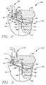
- Figure 3 illustrates a less serviceable embodiment of the present invention as installed within automobile hub assembly 110.
- This sensor system is less serviceable because removal of constant velocity joint 16 is required for replacement of sensor probe 112.
- Capturing cup 114 and magnet carrier 116 are similar to those described with respect to the embodiment of Figure 2.
- Capturing cup 114 includes a sensor seal 118 and is mounted on steering knuckle 120 in a manner similar to that of the second embodiment.
- sensor 122 of sensor probe 112 is positioned between magnet 124 and wheel spindle 14.
- Figure 4 illustrates an embodiment of the present invention installed within automobile hub assembly 130.
- Magnet 132 is secured to magnet carrier 134 by sensor seal 136 that is over-molded to form magnet subassembly 138.
- Magnet carrier 134 is pressed onto an annular groove 140 in an outer surface of constant velocity joint 142 before constant velocity joint 142 is installed into steering knuckle 144.
- Axially extending lip 146 on steering knuckle 144 provides a sealing surface for engagement with sensor seal 136.
- Sensor probe 148 is inserted through aperture 150 in steering knuckle 144 and secured by bolt 152, to be easily removable for service.
- Figure 5 illustrates a fifth embodiment of the present inventtion installed within automobile hub assembly 160.
- This sensor system is similar to that of Figure 1 with magnet subassembly 162 comprising magnet 164, magnet carrier 166 within annular recess 168 of constant velocity joint 170, and sensor seal 172 molded over magnet carrier 166.
- sensor seak 172 extends radially inward over cone portion 174 of magnet carrier 166 and extends radially outwardly as two sealing fingers 176.
- An additional outwardly extending lip 178 provides an interlock with multi-piece capturing cup 180, by entrapping a radially inwardly extending lip of capturing cup 180.
- capturing cup 180 and magnet subassembly 162 can be mounted as a single unit on steering knuckle 182 before installation of constant velocity joint 170 such that such that radially directed portion 184 is clamped between constant velocity joint 170 and inner race 24 in annular recess 186 of constant velocity joint 170.
- Sensor probe 186 is mounted on machined boss 188 of steering knuckle 184 by a bolt through hole 190 and may be sealed by O-rings 192. Again, Sensor probe 186 is easily removable for service by simply removing the bolt from hole 190 and withdrawing the probe radially outwardly with respect to constant velocity joint 170.
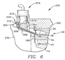
- FIG. 6 illustrates a sixth embodiment of the present invention installed within automobile hub assembly 200.
- Magnet subassembly 202 comprises magnet 204, magnet carrier 206, and sensor seal 208 with sealing fingers 210 similar to those of Figure 5.
- Sensor seal 208 interlocks with a radially inwardly extending lip of capturing cup 212.
- sensor probe 214 is mounted within a sensor mount 216 that is welded or otherwise fixed to capturing cup 212.
- sensor 218 of sensor probe 214 is radially aligned with respect to magnet 204 rather than axially aligned, as in the configurations of the other embodiments.
- a feature that may be considered a "one-piece” design.
- the probe, magnet subassembly, and capturing cup may be handled as a unit and installed on the respective steering knuckle together. This simplifies assembly by reducing the number of separate parts and steps required.
- sensor probe 214 can be inserted in sensor mount 216 of capturing cup 212 before capturing cup is press-fitted or otherwise mounted on steering knuckle 220. Note that this "one-piece" feature is in addition to the ability to remove sensor probe 214 from the sensor system for service.
- the magnets of these embodiments may be formed of a resilient rubber-like material with a magnetic filler and molded as a ring.
- a magnet of that type may be bonded to the magnet carrier.
- a suitable sensor probe for such magnet could be a Hall effect sensor.
- the present invention may employ other encoded targets and probe means.
- a variable reluctance sensor may be used with an encoded target comprising a toothed wheel or other form having alternating metal and non-metal portions.
- a magneto-resistive probe may also be used. However, some of these sensor probes may require more adjustment after installation than others.
- the present invention provides a sensor system for antilock brakes which solves the problems relating to adjustment, inventory, serviceability, sourcing and design requirements of prior designs.
- the sensor system disclosed herein is a stand alone sensing system for antilock braking systems and the like that minimizes the amount of modifications necessary to existing bearings and wheel spindles, is easily serviceable, and requires no adjustment after installation.
- Each of the illustrated embodiments uses an axially or radially oriented magnet, assembled to a formed piece of metal to provide a bracket that is fixed with respect to the rotatable wheel spindle.
Landscapes
- Engineering & Computer Science (AREA)
- Mechanical Engineering (AREA)
- Physics & Mathematics (AREA)
- General Physics & Mathematics (AREA)
- Transportation (AREA)
- General Engineering & Computer Science (AREA)
- Regulating Braking Force (AREA)
- Transmission And Conversion Of Sensor Element Output (AREA)
- Braking Arrangements (AREA)
Abstract
Description
- This invention relates generally to sensor systems and, more particularly, to sensor systems for determining the rotation of shafts and axles for vehicles and other applications.
- Antilock braking systems and traction control systems are now commonplace in the automotive marketplace and are standard equipment on many car models. The basis of these systems is a sensor system that senses wheel speed or rotation and relays that information to a controller The controller dictates, for example, the application of braking force intermittently to keep a respective wheel from skidding or slipping. Such use of the braking system allows vehicles to remain in control during maximum braking and to stop more efficiently. Similarly, controllers can dictate the application of driving force for optimum traction.
- Current sensor systems for antilock brakes and traction control are of three types: 1) non-integrated variable reluctance type, 2) integrated hub assembly type, and 3) integrated spindle sensor bearing type. Non-integrated variable reluctance sensors often require adjustment after installation. Integrated hub assembly units require a large number of individual parts, introducing problems relating to inventory, installation and serviceability of those parts. Integrated spindle sensor bearings can limit an automotive manufacturer to a single supplier and may require new bearing designs to incorporate the sensor and encoder.
- The foregoing illustrates limitations known to exist in present sensor systems for antilock brakes and the like. Thus, it is apparent that it would be advantageous to provide an alternative directed to overcoming one or more of the limitations set forth above. Accordingly, a suitable alternative is provided including features more fully disclosed hereinafter.
- In one aspect of the invention, this is accomplished by providing a sensor system for antilock brakes and the like comprising an encoded target, target mounting means, and probe means. The target mounting means is adapted to be clamped between a constant velocity joint and a spindle bearing inner race, such that the encoded target rotates with a wheel spindle over which the spindle bearing inner race is mounted. The probe means is adapted to be mounted on a steering knuckle within which the constant velocity joint is mounted, such that the probe means senses the encoded target and generates a signal indicative of rotation of the wheel spindle.
- The foregoing and other aspects of the invention will be apparent from the following detailed description of the invention when considered with the accompanying drawing figures.
-
- Fig. 1 is a cross sectional view of an automobile hub assembly having a sensor system for antilock brakes and the like installed therein, illustrating one embodiment of the present invention;
- Fig. 2 is a cross sectional view similar to Fig. 1 illustrating a second embodiment of the present invention;
- Fig. 3 is a cross sectional view similar to Fig. 1 illustrating a third embodiment of the present invention;
- Fig. 4 is a cross sectional view similar to Fig. 1 illustrating a fourth embodiment of the present invention;
- Fig. 5 is a cross sectional view similar to Fig. 1 illustrating a fifth embodiment of the present invention; and
- Fig. 6 is a cross sectional view similar to Fig. 1 illustrating a sixth embodiment of the present invention.
- In this specification, identical elements in different embodiments are given identical reference characters.
- Referring now to the drawings, Figure 1 illustrates a portion of an
automobile hub assembly 10 as might be used, for example, on a front wheel drive automobile equipped with antilock brakes.Hub assembly 10 includeswheel hub 12,wheel spindle 14,constant velocity joint 16, andsteering knuckle 18.Steering knuckle 18 is supported by the automobile front suspension, not shown, for pivoting by a steering rack and pinion to effect steerage. -
Wheel spindle 14 is an extension ofconstant velocity joint 16 and is mounted insteering knuckle 18 by spindle bearing 20 for rotation relative tosteering knuckle 18.Constant velocity joint 16 provides a universal (pivot) coupling to the automobile transmission and transmits power towheel spindle 14 to effect rotation of a road wheel mounted onwheel hub 12. Spindle bearing 20 includesouter race 22,inner race 24, androlling elements 26 between the races, and is provided with aspindle bearing seal 28 to retain lubricant and restrict entry of contaminants. -
Hub assembly 10 is equipped with a sensor system which includes amagnet subassembly 30 having amagnet 32,magnet carrier 34, andsensor seal 36.Sensor seal 36 serves as a "slinger" and is molded overmagnet carrier 34 and a radially outward portion ofmagnet 32 to holdmagnet 32 in place. Capturingcup 38 is a metal ring having a U-shaped cross section with its cylindrical middle portion mounted withincounterbore surface 40 ofsteering knuckle 18. Capturingcup 38 is dimensioned such that the cylindrical middle portion is engaged bysensor seal 36 to effect sealing of the sensor system. - Capturing
cup 38 andmagnet subassembly 30 are mounted onsteering knuckle 18 beforeconstant velocity joint 16 is installed insteering knuckle 18. Specifically, capturingcup 38 is press-fitted, for example, withincounterbore surface 40 and subassembly 30 is held by engagement ofsensor seal 36 with capturingcup 38 such thatmagnet carrier 34 is suspended radially inward.Constant velocity joint 16 is subsequently installed withinsteering knuckle 18 such thatmagnet carrier 34 pilots magnet subassembly 30 and a portion ofsubassembly 30 is clamped betweenconstant velocity joint 16 and spindle bearinginner race 24. - In the embodiment of Figure 1,
magnet carrier 34 is formed of metal by pressing, drawing, spinning or other convenient method and is configured withcone portion 42 conforming to anouter surface 44 ofconstant velocity joint 16. Radially inward edge ofcone portion 42 is joined toradial face 46 ofmagnet carrier 34 that is received within anannular recess 48 inconstant velocity joint 16.Magnet carrier 34 has an axially directedlip 50 at its radially outward edge for maintaining radial alignment ofmagnet 32 and for providing a key surface over whichsensor seal 36 is molded. - Although
magnet carrier 34 is of a particular annular configuration in Figure 1, other mounting means may be employed with similar effect. For example,magnet carrier 34 may take the form of a bracket with one or more fingers extending radially inwardly to be clamped betweenconstant velocity joint 16 and spindle bearinginner race 24 by abutment with one of those two elements or by other clamping means. In place ofcone portion 42, other shapes may be used to guide magnet subassembly 30 into a desired position concentric toconstant velocity joint 16 andwheel spindle 14. -
Sensor probe 52 is adapted to be mounted onsteering knuckle 18 such that asensor 54 therein is proximate tomagnet 32 for sensing a magnetic field produced bymagnet 32 and for generating a signal indicative of rotation ofwheel spindle 14.Sensor 54 may be a Hall effect sensor or other known magnetic field sensing device. In the embodiment of Figure 1, for example,sensor probe 52 is located by amachined boss 56 and is inserted through anaperture 58 in a portion ofsteering knuckle 18 overlyingconstant velocity joint 16 andcone portion 42 ofmagnet carrier 34. -
Collar portion 60 overlies machinedboss 56 onsteering knuckle 18 to provide a stop surface for locatingsensor 64 and to provide a barrier to contamination. Reduceddiameter portion 64 extends through a counterbore ofaperture 58 and terminates in a beveled end atsensor 54. O-rings 66, provided within an annular groove, are received within the counterbore ofaperture 58 to seal out contamination and to provide frictional retention. A bolt (not shown) securingcollar portion 60 to steeringknuckle 18, or other keying means, may be provided to drient the beveled end andsensor 54 with respect tomagnet 32. - Once assembled, the sensor system needs no additional adjustment to ensure proper functioning.
Magnet subassembly 30 andsensor probe 52 can be removed to service spindle bearing 20 if necessary. Capturingcup 38 remains pressed insteering knuckle 18 and provides axial location ofmagnet carrier 34 and, also, a controlled surface for extending the life ofsensor seal 36.Sensor probe 52 is highly serviceable since the probe can be removed simply by removing any securing bolt andpulling sensor probe 52 radially outwardly relative toconstant velocity joint 16, in the axial direction ofaperture 58. - Figure 2 illustrates a portion of an
automobile hub assembly 70 includingwheel hub 12,wheel spindle 14,constant velocity joint 16, and spindle bearing 20 common to those ofhub assembly 10, described above.Hub assembly 70 is equipped with a sensor system which includes amagnet subassembly 72 comprisingmagnet 74 and amagnet carrier 76, and a spun-oncup 78 for securingmagnet 74 tomagnet carrier 76.Magnet carrier 76 has a cone shapedportion 80 andstep portion 82 conforming toouter surface 44 ofconstant velocity joint 16. - Capturing
cup 84 comprising acup ring 86 having an L-shaped cross section,sensor seal 88, and, radially facingbracket 90. Capturingcup 84 is dimensioned such thatsensor seal 88 engagesouter surface 44 ofconstant velocity joint 16.Sensor probe 92 is mounted in a slot within capturingcup 84 such thatsensor 93 is proximate tomagnet 74 to sense a magnetic field produced bymagnet 74 to generate a signal indicative of rotation ofwheel spindle 14. Aresilient guide 94 may be formed insensor probe 92 to ensure proper axial location ofmagnet 74.Sensor probe 92 is removable for service by removing capturingcup 84 overmagnet subassembly 72 and withdrawingsensor probe 92 radially inwardly from the cup. - Capturing
cup 84 andmagnet subassembly 30 are mounted onsteering knuckle 96 before constant velocity joint 16 is installed. Specifically, capturingcup 84 is press-fitted or bolted, for example, withincounterbore surface 98 andmagnet subassembly 72 is held by engagement ofsensor seal 88 such thatmagnet carrier 76 is suspended radially inward. constant velocity joint 16 is subsequently installed withinsteering knuckle 96 such thatmagnet carrier 76pilots magnet subassembly 72 and a radially inwardly extendingportion 100 is clamped between constant velocity joint 16 and spindle bearinginner race 24. - Figure 3 illustrates a less serviceable embodiment of the present invention as installed within
automobile hub assembly 110. This sensor system is less serviceable because removal of constant velocity joint 16 is required for replacement ofsensor probe 112. Capturingcup 114 andmagnet carrier 116 are similar to those described with respect to the embodiment of Figure 2. Capturingcup 114 includes asensor seal 118 and is mounted onsteering knuckle 120 in a manner similar to that of the second embodiment. However, in the third embodiment,sensor 122 ofsensor probe 112 is positioned betweenmagnet 124 andwheel spindle 14. - Figure 4 illustrates an embodiment of the present invention installed within
automobile hub assembly 130.Magnet 132 is secured tomagnet carrier 134 bysensor seal 136 that is over-molded to formmagnet subassembly 138.Magnet carrier 134 is pressed onto anannular groove 140 in an outer surface of constant velocity joint 142 before constant velocity joint 142 is installed intosteering knuckle 144.Axially extending lip 146 onsteering knuckle 144 provides a sealing surface for engagement withsensor seal 136.Sensor probe 148 is inserted throughaperture 150 insteering knuckle 144 and secured bybolt 152, to be easily removable for service. - Figure 5 illustrates a fifth embodiment of the present inventtion installed within
automobile hub assembly 160. This sensor system is similar to that of Figure 1 withmagnet subassembly 162 comprisingmagnet 164,magnet carrier 166 within annular recess 168 of constant velocity joint 170, andsensor seal 172 molded overmagnet carrier 166. However,sensor seak 172 extends radially inward overcone portion 174 ofmagnet carrier 166 and extends radially outwardly as two sealingfingers 176. An additional outwardly extendinglip 178 provides an interlock withmulti-piece capturing cup 180, by entrapping a radially inwardly extending lip of capturingcup 180. - As with the first embodiment, capturing
cup 180 andmagnet subassembly 162 can be mounted as a single unit onsteering knuckle 182 before installation of constant velocity joint 170 such that such that radially directedportion 184 is clamped between constant velocity joint 170 andinner race 24 inannular recess 186 of constant velocity joint 170.Sensor probe 186 is mounted on machinedboss 188 ofsteering knuckle 184 by a bolt throughhole 190 and may be sealed by O-rings 192. Again,Sensor probe 186 is easily removable for service by simply removing the bolt fromhole 190 and withdrawing the probe radially outwardly with respect to constant velocity joint 170. - Figure 6 illustrates a sixth embodiment of the present invention installed within
automobile hub assembly 200.Magnet subassembly 202 comprisesmagnet 204,magnet carrier 206, andsensor seal 208 with sealingfingers 210 similar to those of Figure 5.Sensor seal 208 interlocks with a radially inwardly extending lip of capturingcup 212. Unlike other embodiments,sensor probe 214 is mounted within asensor mount 216 that is welded or otherwise fixed to capturingcup 212. Another difference is thatsensor 218 ofsensor probe 214 is radially aligned with respect tomagnet 204 rather than axially aligned, as in the configurations of the other embodiments. - Several of these embodiments include a feature that may be considered a "one-piece" design. Specifically, the probe, magnet subassembly, and capturing cup may be handled as a unit and installed on the respective steering knuckle together. This simplifies assembly by reducing the number of separate parts and steps required. For example, in the embodiment of Figure 6,
sensor probe 214 can be inserted insensor mount 216 of capturingcup 212 before capturing cup is press-fitted or otherwise mounted onsteering knuckle 220. Note that this "one-piece" feature is in addition to the ability to removesensor probe 214 from the sensor system for service. - The magnets of these embodiments may be formed of a resilient rubber-like material with a magnetic filler and molded as a ring. A magnet of that type may be bonded to the magnet carrier. A suitable sensor probe for such magnet could be a Hall effect sensor. In addition, the present invention may employ other encoded targets and probe means. For example, a variable reluctance sensor may be used with an encoded target comprising a toothed wheel or other form having alternating metal and non-metal portions. A magneto-resistive probe may also be used. However, some of these sensor probes may require more adjustment after installation than others.
- The present invention provides a sensor system for antilock brakes which solves the problems relating to adjustment, inventory, serviceability, sourcing and design requirements of prior designs. The sensor system disclosed herein is a stand alone sensing system for antilock braking systems and the like that minimizes the amount of modifications necessary to existing bearings and wheel spindles, is easily serviceable, and requires no adjustment after installation. Each of the illustrated embodiments uses an axially or radially oriented magnet, assembled to a formed piece of metal to provide a bracket that is fixed with respect to the rotatable wheel spindle.
- Although the invention has been particularly shown and described with reference to preferred embodiments, it will be under-stood by those skilled in the art that the foregoing and other changes in form and details may be made therein without departing from the spirit and scope of the invention, as defined by the claims appended hereto.
Claims (23)
- A sensor system for antilock brakes and the like, the system comprising:
an encoded target;
target mounting means, adapted to be clamped between a constant velocity joint and a spindle bearing inner race, for mounting the encoded target for rotation with a wheel spindle over which the spindle bearing inner race is mounted; and
probe means, adapted to be mounted on a steering knuckle within which the constant velocity joint is mounted, for sensing the encoded target and for generating a signal indicative of rotation of the wheel spindle. - The sensor system according to claim 1, wherein the probe means is removable from the steering knuckle for service without removal of the constant velocity joint from the steering knuckle.
- The sensor system according to claim 1, wherein the mounting means includes a target carrier comprising a metal ring configured to fit against an outer surface of the constant velocity joint.
- The sensor system according to claim 1, wherein the encoded target is a magnet and wherein the probe means senses a magnetic field produced by the magnet to generate the signal indicative of rotation.
- The sensor system according to claim 1, wherein the probe means is a variable reluctance sensor.
- A method of mounting a sensor system for antilock brakes and the like, the method comprising:
providing a capturing cup and a subassembly, the subassembly including an encoded target and a target carrier;
mounting the capturing cup on a steering knuckle, before a constant velocity joint is installed in the steering knuckle, such that the subassembly is captured by the capturing cup;
installing the constant velocity joint in the steering knuckle such that the target carrier pilots the subassembly and such that a portion of the subassembly is clamped between the constant velocity joint and a spindle bearing inner race; and
mounting a sensor probe on the steering knuckle such that the sensor probe senses the encoded target and generates a signal indicative of rotation of a spindle over which the spindle bearing is mounted. - The method according to claim 6, wherein the mounting of the sensor probe in the steering knuckle permits removal of the sensor probe from the steering knuckle for service without removing the constant velocity joint from the steering knuckle.
- The method according to claim 6, wherein the subassembly further comprises a seal fixed to the target carrier and in engagement with the capturing cup.
- The method according to claim 6, wherein the subassembly further comprises a seal fixed to the capturing cup and in engagement with the target carrier.
- The method according to claim 6, wherein the sensor probe is mounted in an aperture of the steering knuckle and extends through the steering knuckle to a location proximate to the encoded target.
- The method according to claim 6, wherein the encoded target is a magnet and the probe means senses a magnetic field produced by the magnet to generate a signal indicative of rotation.
- The method according to claim 6, wherein the probe means is a variable reluctance sensor.
- A method of mounting a sensor system for antilock brakes and the like, the method comprising:
providing a subassembly including an encoded target and a target carrier;
mounting the subassembly on an outer surface of a constant velocity joint before the constant velocity joint is installed in a steering knuckle;
installing the constant velocity joint in the steering knuckle; and
mounting a sensor probe on the steering knuckle such that the sensor probe senses the encoded target and generates a signal indicative of rotation of a spindle over which the spindle bearing is mounted. - The sensor system according to claim 13, wherein the sub-assembly further comprises a seal and wherein the installing of the constant velocity joint in the steering knuckle effects engagement of the steering knuckle by the seal.
- The method according to claim 13, wherein the sensor probe is mounted in an aperture of the steering knuckle and extends through the steering knuckle to a location proximate to the encoded target.
- The method according to claim 13, wherein the encoded target is a magnet and the probe means senses a magnetic field produced by the magnet to generate a signal indicative of rotation.
- The method according to claim 13, wherein the probe means is a variable reluctance sensor.
- A sensor system for antilock brakes and the like, the system comprising:
an encoded target;
mounting means, adapted to be mounted on an outer surface of a constant velocity joint for rotation with a wheel spindle fixed to the constant velocity joint; and
probe means, adapted to be mounted on a steering knuckle and in proximity to the encoded target, for sensing the encoded target and for producing a signal indicative of rotation of the wheel spindle. - The sensor system according to claim 18, wherein the probe means is removable from the steering knuckle for service without removal of the constant velocity joint from the steering knuckle.
- The sensor system according to claim 18, further comprising a seal mounted on the target carrier such that the seal is engageable with the steering knuckle when the constant velocity joint is installed within the steering knuckle.
- The sensor system according to claim 18, wherein the mounting means includes a target carrier comprising a metal ring configured to fit against an outer surface of the constant velocity joint.
- The method according to claim 18, wherein the encoded target is a magnet and the probe means senses a magnetic field produced by the magnet to generate a signal indicative of rotation.
- The method according to claim 18, wherein the probe means is a variable reluctance sensor.
Applications Claiming Priority (2)
| Application Number | Priority Date | Filing Date | Title |
|---|---|---|---|
| US07/969,659 US5287738A (en) | 1992-10-30 | 1992-10-30 | Sensor system for antilock brakes |
| US969659 | 1992-10-30 |
Publications (2)
| Publication Number | Publication Date |
|---|---|
| EP0595728A1 true EP0595728A1 (en) | 1994-05-04 |
| EP0595728B1 EP0595728B1 (en) | 1998-04-29 |
Family
ID=25515825
Family Applications (1)
| Application Number | Title | Priority Date | Filing Date |
|---|---|---|---|
| EP19930402681 Expired - Lifetime EP0595728B1 (en) | 1992-10-30 | 1993-10-29 | Sensor system for antilock brakes |
Country Status (11)
| Country | Link |
|---|---|
| US (1) | US5287738A (en) |
| EP (1) | EP0595728B1 (en) |
| JP (1) | JP3044312B2 (en) |
| KR (1) | KR100208056B1 (en) |
| CN (1) | CN1043440C (en) |
| AR (1) | AR248457A1 (en) |
| AU (1) | AU663453B2 (en) |
| DE (1) | DE69318250T2 (en) |
| ES (1) | ES2118920T3 (en) |
| TW (1) | TW248547B (en) |
| WO (1) | WO1994010549A1 (en) |
Cited By (3)
| Publication number | Priority date | Publication date | Assignee | Title |
|---|---|---|---|---|
| DE4445610A1 (en) * | 1994-12-21 | 1996-06-27 | Kaco Gmbh Co | Seal with stationary and rotational housing parts also sealing part |
| DE19745818C2 (en) * | 1996-10-16 | 2001-02-22 | Sabo Ind & Comercio Ltda | Sealing arrangement |
| EP1447240A2 (en) * | 2003-02-17 | 2004-08-18 | Aktiebolaget SKF | Sealing device for a wheel hub group |
Families Citing this family (26)
| Publication number | Priority date | Publication date | Assignee | Title |
|---|---|---|---|---|
| FR2694082B1 (en) * | 1992-07-23 | 1994-09-16 | Skf France | Composite ring encoder for bearings and information sensor bearings, comprising such an encoder. |
| US5291130A (en) * | 1993-01-25 | 1994-03-01 | Eaton Corporation | Vehicle wheel speed sensor employing an adaptable rotor cap |
| FR2717266B1 (en) * | 1994-03-08 | 1996-04-19 | Roulements Soc Nouvelle | Device for detecting the speed of rotation of a rolling bearing. |
| US5510708A (en) * | 1994-10-20 | 1996-04-23 | General Motors Corporation | Variable reluctance rotation sensor with leakage magnetic flux sensing |
| FR2732421B1 (en) * | 1995-03-28 | 1997-05-16 | Skf France | BEARING PROVIDED WITH AN INTEGRATED ROTATION SPEED DETECTION DEVICE |
| DE19514801A1 (en) * | 1995-04-21 | 1996-10-24 | Wittur Aufzugteile Gmbh & Co | Method for controlling and monitoring the operation of an elevator system and roller bearings for use in the method |
| US5762425A (en) * | 1996-01-24 | 1998-06-09 | Nsk Ltd. | Rolling bearing unit with tachometer |
| JPH1123600A (en) * | 1997-07-04 | 1999-01-29 | Nippon Seiko Kk | Rolling bearing unit with rotating speed detecting device |
| JP3862453B2 (en) * | 1999-09-10 | 2006-12-27 | Ntn株式会社 | Wheel bearing device |
| US6796404B1 (en) | 2000-03-22 | 2004-09-28 | American Axle & Manufacturing, Inc. | Cover pan ABS sensor |
| JP4857485B2 (en) * | 2001-04-25 | 2012-01-18 | 日本精工株式会社 | Rotation support device for wheels with encoder |
| JP2003120703A (en) | 2001-10-16 | 2003-04-23 | Nsk Ltd | Rotation support device for driving wheel with rotation detecting device |
| KR20040031252A (en) * | 2002-10-04 | 2004-04-13 | 현대자동차주식회사 | Flexible dust cover for preventing particles |
| US20060186627A1 (en) * | 2003-03-10 | 2006-08-24 | Katsura Koyagi | Axle-supporting device |
| DE10338960B4 (en) | 2003-08-25 | 2014-05-08 | Schaeffler Technologies Gmbh & Co. Kg | Sealing arrangement with encoder and magnetization head for the encoder |
| JP4691879B2 (en) * | 2003-09-11 | 2011-06-01 | 日本精工株式会社 | Drive wheel hub unit |
| DE102004048654A1 (en) * | 2004-10-06 | 2006-04-20 | Fag Kugelfischer Ag & Co. Ohg | Wheel bearing unit for vehicle, has sensor and repelling ring, which are fixed at side of vehicle, where repelling ring stands in sealed-operative connection with housing and sensor is fixed or integrated at or in repelling ring |
| US20080159673A1 (en) * | 2005-01-27 | 2008-07-03 | Ntn Corporation | Vehicle Wheel Bearing Apparatus |
| JP2009275868A (en) * | 2008-05-16 | 2009-11-26 | Ntn Corp | Wheel bearing device with rotation speed detector |
| WO2009139179A1 (en) * | 2008-05-16 | 2009-11-19 | Ntn株式会社 | Vehicle axle bearing device with rotational speed detecting apparatus |
| DE102009014923C5 (en) * | 2009-03-25 | 2015-07-23 | Ab Skf | Double row tapered roller bearing, in particular for supporting a rotor shaft of a wind turbine |
| US8353390B2 (en) * | 2010-03-10 | 2013-01-15 | GM Global Technology Operations LLC | Splash shield for brake corner assembly |
| FR2966892B1 (en) * | 2010-10-28 | 2013-08-09 | Peugeot Citroen Automobiles Sa | WHEEL SUSPENSION DEVICE FOR A MOTOR VEHICLE WITH A WHEEL BEARING PROTECTION RING |
| WO2015125124A1 (en) * | 2014-02-24 | 2015-08-27 | Mahindra And Mahindra Limited | An arrangement for packaging an engine of a vehicle |
| KR101822856B1 (en) * | 2016-02-22 | 2018-01-29 | 서한산업(주) | An axle assembly for a vechicle comprising a sealing member |
| ITUA20162314A1 (en) * | 2016-04-05 | 2017-10-05 | Skf Ab | Bearing-hub assembly configured to mount a suspension to the upright. |
Citations (6)
| Publication number | Priority date | Publication date | Assignee | Title |
|---|---|---|---|---|
| US3927339A (en) * | 1971-12-07 | 1975-12-16 | Daimler Benz Ag | Frequency transmitters for producing control signals controlling the brake force in motor vehicle wheels |
| WO1987000290A1 (en) * | 1985-07-01 | 1987-01-15 | Saab-Scania Aktiebolag | Arrangement for fixing an impulse wheel |
| DE3703395A1 (en) * | 1987-02-05 | 1988-08-18 | Porsche Ag | Rotor of a wheel speed sensor for antilocking systems of motor vehicles |
| EP0357870A2 (en) * | 1988-08-24 | 1990-03-14 | Rockwell International Corporation | Unitary rotational speed sensor |
| JPH04244966A (en) * | 1991-01-31 | 1992-09-01 | Nissan Motor Co Ltd | Mounting structure of sensor for wheel revolution number for antiskid control |
| EP0522933A1 (en) * | 1991-07-05 | 1993-01-13 | Skf France | Angular velocity sensor and roller bearing equipped with such a sensor |
Family Cites Families (10)
| Publication number | Priority date | Publication date | Assignee | Title |
|---|---|---|---|---|
| US4954775A (en) * | 1986-03-03 | 1990-09-04 | Emhart Industries Inc. | Automotive wheel speed sensor assembly with multipole rotor mounted on wheel bearing spindle |
| US4904936A (en) * | 1986-03-03 | 1990-02-27 | Emhart Industries, Inc. | Automotive wheel speed sensor including ferromagnetic flux carrying cup closing an opening in the wheel bearing housing |
| US4969753A (en) * | 1987-05-29 | 1990-11-13 | Ntn Toyo Bearing Co., Ltd. | Wheel bearing assembly for automotive wheel |
| JP2633255B2 (en) * | 1987-07-23 | 1997-07-23 | 光洋精工株式会社 | Axle bearing device |
| EP0397309A2 (en) * | 1989-05-12 | 1990-11-14 | The Timken Company | Bearing assemblies |
| FR2653192B1 (en) * | 1989-10-16 | 1995-01-20 | Roulements Soc Nouvelle | BEARING COMPRISING A SPEED DETECTION DEVICE. |
| US5157966A (en) * | 1990-02-20 | 1992-10-27 | The Torrington Company | Transmission speed sensor |
| AU620714B2 (en) * | 1990-02-20 | 1992-02-20 | Torrington Company, The | Transmission output speed sensor |
| US4988220A (en) * | 1990-05-14 | 1991-01-29 | General Motors Corporation | Servicable wheel speed sensor assembly |
| US5011302A (en) * | 1990-06-25 | 1991-04-30 | The Budd Company | Motor vehicle hub and bearing with integrated anti-lock brake sensor mounting |
-
1992
- 1992-10-30 US US07/969,659 patent/US5287738A/en not_active Expired - Lifetime
-
1993
- 1993-05-07 JP JP51102993A patent/JP3044312B2/en not_active Expired - Lifetime
- 1993-05-07 KR KR1019940702273A patent/KR100208056B1/en not_active IP Right Cessation
- 1993-05-07 AU AU43800/93A patent/AU663453B2/en not_active Expired
- 1993-05-07 WO PCT/US1993/004693 patent/WO1994010549A1/en unknown
- 1993-05-19 TW TW82103947A patent/TW248547B/zh active
- 1993-06-11 AR AR32515693A patent/AR248457A1/en active
- 1993-10-27 CN CN93119683A patent/CN1043440C/en not_active Expired - Fee Related
- 1993-10-29 EP EP19930402681 patent/EP0595728B1/en not_active Expired - Lifetime
- 1993-10-29 ES ES93402681T patent/ES2118920T3/en not_active Expired - Lifetime
- 1993-10-29 DE DE69318250T patent/DE69318250T2/en not_active Expired - Lifetime
Patent Citations (6)
| Publication number | Priority date | Publication date | Assignee | Title |
|---|---|---|---|---|
| US3927339A (en) * | 1971-12-07 | 1975-12-16 | Daimler Benz Ag | Frequency transmitters for producing control signals controlling the brake force in motor vehicle wheels |
| WO1987000290A1 (en) * | 1985-07-01 | 1987-01-15 | Saab-Scania Aktiebolag | Arrangement for fixing an impulse wheel |
| DE3703395A1 (en) * | 1987-02-05 | 1988-08-18 | Porsche Ag | Rotor of a wheel speed sensor for antilocking systems of motor vehicles |
| EP0357870A2 (en) * | 1988-08-24 | 1990-03-14 | Rockwell International Corporation | Unitary rotational speed sensor |
| JPH04244966A (en) * | 1991-01-31 | 1992-09-01 | Nissan Motor Co Ltd | Mounting structure of sensor for wheel revolution number for antiskid control |
| EP0522933A1 (en) * | 1991-07-05 | 1993-01-13 | Skf France | Angular velocity sensor and roller bearing equipped with such a sensor |
Cited By (5)
| Publication number | Priority date | Publication date | Assignee | Title |
|---|---|---|---|---|
| DE4445610A1 (en) * | 1994-12-21 | 1996-06-27 | Kaco Gmbh Co | Seal with stationary and rotational housing parts also sealing part |
| DE19745818C2 (en) * | 1996-10-16 | 2001-02-22 | Sabo Ind & Comercio Ltda | Sealing arrangement |
| DE19745818C5 (en) * | 1996-10-16 | 2013-10-24 | Sabó Indústria e Comércio Ltda. | sealing arrangement |
| EP1447240A2 (en) * | 2003-02-17 | 2004-08-18 | Aktiebolaget SKF | Sealing device for a wheel hub group |
| EP1447240A3 (en) * | 2003-02-17 | 2006-11-02 | Aktiebolaget SKF | Sealing device for a wheel hub group |
Also Published As
| Publication number | Publication date |
|---|---|
| KR940703998A (en) | 1994-12-12 |
| AR248457A1 (en) | 1995-08-18 |
| AU4380093A (en) | 1994-05-24 |
| DE69318250T2 (en) | 1998-12-17 |
| JPH07502824A (en) | 1995-03-23 |
| ES2118920T3 (en) | 1998-10-01 |
| EP0595728B1 (en) | 1998-04-29 |
| CN1088302A (en) | 1994-06-22 |
| JP3044312B2 (en) | 2000-05-22 |
| DE69318250D1 (en) | 1998-06-04 |
| KR100208056B1 (en) | 1999-07-15 |
| TW248547B (en) | 1995-06-01 |
| US5287738A (en) | 1994-02-22 |
| CN1043440C (en) | 1999-05-19 |
| WO1994010549A1 (en) | 1994-05-11 |
| AU663453B2 (en) | 1995-10-05 |
Similar Documents
| Publication | Publication Date | Title |
|---|---|---|
| US5287738A (en) | Sensor system for antilock brakes | |
| EP0521693B1 (en) | Bearing assembly with speed sensor and process for assembling the same | |
| US6675640B2 (en) | Axle end wheel sensor for a vehicle, such as a truck or a trailer | |
| US5248939A (en) | Apparatus for sensing the direction and speed of a steering wheel shaft using hall effect sensors in a detachable sensor mounting | |
| US5011302A (en) | Motor vehicle hub and bearing with integrated anti-lock brake sensor mounting | |
| CA1051108A (en) | Quick-installation vehicle wheel speed sensor | |
| US5097701A (en) | Automobile wheel hub | |
| EP0767385B1 (en) | A bearing unit with a quick mounting rotational speed detector | |
| JPH10260196A (en) | Roller bearing with single-row taper | |
| EP2083186A1 (en) | Brake shield | |
| EP1426257A2 (en) | Protective cap for wheel support bearing assembly | |
| US5121998A (en) | Bearing assembly capable of monitoring angular velocity | |
| US5739684A (en) | Unitarily formed hub and ABS exciter ring | |
| EP0236335B1 (en) | Axle assembly | |
| EP0507340B1 (en) | Hub assembly with integral ABS exciter ring seal | |
| JP3973317B2 (en) | Manufacturing method of wheel bearing device | |
| KR20160122149A (en) | Rolling-riveted wheel bearing arrangement with a stepped inner ring | |
| JPS5851496B2 (en) | Wheel speed sensor assembly | |
| US7194921B1 (en) | Speed-sensing device and method for assembling the same | |
| EP1591684A1 (en) | Sensor assembly body, seal device, and rolling bearing device for motor vehicle | |
| EP0578483B1 (en) | Bearings | |
| CN113454356A (en) | Locking structure of component | |
| JP2007178254A (en) | Wheel speed detection device | |
| JP4116729B2 (en) | Wheel bearing device | |
| JP2000162072A (en) | Bearing for wheel |
Legal Events
| Date | Code | Title | Description |
|---|---|---|---|
| PUAI | Public reference made under article 153(3) epc to a published international application that has entered the european phase |
Free format text: ORIGINAL CODE: 0009012 |
|
| AK | Designated contracting states |
Kind code of ref document: A1 Designated state(s): DE ES FR GB IT SE |
|
| 17P | Request for examination filed |
Effective date: 19940519 |
|
| 17Q | First examination report despatched |
Effective date: 19951017 |
|
| GRAG | Despatch of communication of intention to grant |
Free format text: ORIGINAL CODE: EPIDOS AGRA |
|
| GRAG | Despatch of communication of intention to grant |
Free format text: ORIGINAL CODE: EPIDOS AGRA |
|
| GRAH | Despatch of communication of intention to grant a patent |
Free format text: ORIGINAL CODE: EPIDOS IGRA |
|
| GRAH | Despatch of communication of intention to grant a patent |
Free format text: ORIGINAL CODE: EPIDOS IGRA |
|
| GRAA | (expected) grant |
Free format text: ORIGINAL CODE: 0009210 |
|
| AK | Designated contracting states |
Kind code of ref document: B1 Designated state(s): DE ES FR GB IT SE |
|
| REF | Corresponds to: |
Ref document number: 69318250 Country of ref document: DE Date of ref document: 19980604 |
|
| ET | Fr: translation filed | ||
| ITF | It: translation for a ep patent filed | ||
| PG25 | Lapsed in a contracting state [announced via postgrant information from national office to epo] |
Ref country code: SE Free format text: LAPSE BECAUSE OF FAILURE TO SUBMIT A TRANSLATION OF THE DESCRIPTION OR TO PAY THE FEE WITHIN THE PRESCRIBED TIME-LIMIT Effective date: 19980729 |
|
| REG | Reference to a national code |
Ref country code: ES Ref legal event code: FG2A Ref document number: 2118920 Country of ref document: ES Kind code of ref document: T3 |
|
| PLBE | No opposition filed within time limit |
Free format text: ORIGINAL CODE: 0009261 |
|
| STAA | Information on the status of an ep patent application or granted ep patent |
Free format text: STATUS: NO OPPOSITION FILED WITHIN TIME LIMIT |
|
| 26N | No opposition filed | ||
| REG | Reference to a national code |
Ref country code: GB Ref legal event code: IF02 |
|
| PGFP | Annual fee paid to national office [announced via postgrant information from national office to epo] |
Ref country code: FR Payment date: 20121031 Year of fee payment: 20 Ref country code: DE Payment date: 20121023 Year of fee payment: 20 |
|
| PGFP | Annual fee paid to national office [announced via postgrant information from national office to epo] |
Ref country code: ES Payment date: 20121026 Year of fee payment: 20 Ref country code: GB Payment date: 20121019 Year of fee payment: 20 Ref country code: IT Payment date: 20121026 Year of fee payment: 20 |
|
| REG | Reference to a national code |
Ref country code: DE Ref legal event code: R071 Ref document number: 69318250 Country of ref document: DE |
|
| REG | Reference to a national code |
Ref country code: DE Ref legal event code: R071 Ref document number: 69318250 Country of ref document: DE |
|
| REG | Reference to a national code |
Ref country code: GB Ref legal event code: PE20 Expiry date: 20131028 |
|
| PG25 | Lapsed in a contracting state [announced via postgrant information from national office to epo] |
Ref country code: GB Free format text: LAPSE BECAUSE OF EXPIRATION OF PROTECTION Effective date: 20131028 Ref country code: DE Free format text: LAPSE BECAUSE OF EXPIRATION OF PROTECTION Effective date: 20131030 |
|
| REG | Reference to a national code |
Ref country code: ES Ref legal event code: FD2A Effective date: 20140925 |
|
| PG25 | Lapsed in a contracting state [announced via postgrant information from national office to epo] |
Ref country code: ES Free format text: LAPSE BECAUSE OF EXPIRATION OF PROTECTION Effective date: 20131030 |