EP0595708B1 - Dispositif anti-retrait d'isolation, pour câble de puissance à isolation synthétique - Google Patents
Dispositif anti-retrait d'isolation, pour câble de puissance à isolation synthétique Download PDFInfo
- Publication number
- EP0595708B1 EP0595708B1 EP93402622A EP93402622A EP0595708B1 EP 0595708 B1 EP0595708 B1 EP 0595708B1 EP 93402622 A EP93402622 A EP 93402622A EP 93402622 A EP93402622 A EP 93402622A EP 0595708 B1 EP0595708 B1 EP 0595708B1
- Authority
- EP
- European Patent Office
- Prior art keywords
- ring
- insulation
- conductor
- shoulder
- cable
- Prior art date
- Legal status (The legal status is an assumption and is not a legal conclusion. Google has not performed a legal analysis and makes no representation as to the accuracy of the status listed.)
- Expired - Lifetime
Links
Images

Classifications
-
- H—ELECTRICITY
- H02—GENERATION; CONVERSION OR DISTRIBUTION OF ELECTRIC POWER
- H02G—INSTALLATION OF ELECTRIC CABLES OR LINES, OR OF COMBINED OPTICAL AND ELECTRIC CABLES OR LINES
- H02G15/00—Cable fittings
- H02G15/08—Cable junctions
- H02G15/10—Cable junctions protected by boxes, e.g. by distribution, connection or junction boxes
- H02G15/103—Cable junctions protected by boxes, e.g. by distribution, connection or junction boxes with devices for relieving electrical stress
-
- H—ELECTRICITY
- H02—GENERATION; CONVERSION OR DISTRIBUTION OF ELECTRIC POWER
- H02G—INSTALLATION OF ELECTRIC CABLES OR LINES, OR OF COMBINED OPTICAL AND ELECTRIC CABLES OR LINES
- H02G15/00—Cable fittings
- H02G15/02—Cable terminations
- H02G15/06—Cable terminating boxes, frames or other structures
Definitions
- the present invention relates to power cables, medium, high or very high voltage, conductor covered with synthetic insulation. It relates more particularly to an anti-shrinkage insulation device, for such a power cable.
- the document EP-A-0199742 describes a junction of two cables as mentioned above, the ends of which to be connected are previously prepared.
- the conductors of the two cables are mechanically interconnected end-to-end and are surrounded by a metal adapter fixed on the end parts of the insulations of the two cables.
- the adapter is cylindrical and formed in two semi-cylindrical parts which can be joined together.
- a monolithic sleeve covers and encloses the adapter as well as the portions of the cables on either side of this adapter.
- This adapter is designed to present two annular, non-terminal interior walls which pass through the two stripped conductors of the two cables and which form two stops for the front faces of the insulations of one and the other of the two cables. Its ends cover the end parts of the insulations, previously rendered with a slightly reduced outside diameter, for alignment of the outside surfaces of the insulations and the adapter. They are anchored in their end parts, by engagement of an internal annular rib provided on each end of the adapter in a corresponding groove provided on the end part of the insulation of each cable.
- the aforementioned adapter ensures, in addition to its normal function of adaptation to the diameter of the insulations, that additional blocking of the insulations with respect to each other. It therefore requires that the dimensioning of the prepared end of each cable has been defined and carried out with precision, as a function of the dimensions of this adapter and taking into account the method of connecting the conductors, for the proper fitting of the adapter. after the conductors have been connected. It makes it difficult to connect the conductors, during which the handling of the prepared ends and the forces exerted on the conductors can lead to a more or less significant withdrawal of the insulations and then give rise to problems or an impossibility of fitting in the correct position of the adapter.
- the object of the present invention is to avoid the drawbacks of this known solution, by carrying out the insulation blocking of such a cable directly on a prepared end thereof and leaving free of any particular dimensional adjustment the said prepared end relatively to equipment that it must receive.
- an anti-shrinkage insulation device for synthetic insulation power cable covering a conductor with the exception of a prepared end of said cable, intended to receive connection equipment, where the stripped insulation is set back on the also stripped conductor, comprising a stop element against the front face of said insulation and a fixing element on the periphery of the end portion of said insulation, characterized in that it is constituted by a shouldered ring, comprising two annular shoulders defining, one, said stop element and, the other, said fixing element, mounted directly in place on said stripped conductor and the terminal part of the insulation of said prepared end of said cable and secured to said stripped conductor by retaining means integrated into said ring.
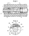
- the junction illustrated in Figure 1 is of known type. It provides the connection of two power cables 1 and 2 with synthetic insulation 3, 4 covering their solid central or multi-strand conductor 5, 6.
- Each of these cables further comprises, in a known manner and not shown, a semiconductor screen surrounding their insulation, an external protective sheath, and a metal screen directly under the protective sheath and capable of being fixed to it.
- the ends of the cables thus connected have been previously stripped in a stepped manner and are said to be prepared. They are also equipped, as soon as they are prepared, with an anti-shrinkage insulation device 10, mounted on each of them before the junction is made.
- This junction comprises a mechanical connection 7 of the conductors 5, 6, which is produced for example by butt welding or by means of an electrical connection, a conductive casing 8, which surrounds the connection 7 and the terminal portion of diameter previously reduced from both of the insulations 3 and 4, as well as the anti-shrinkage insulation device 10 already mounted on each prepared end, and an elastic protective sleeve 9 which tightly covers the casing 8 and the portions on either side of the insulations.
- This sleeve 9 is, in a well known manner and not shown, with an inner semiconductor layer in contact with the casing 8, along the latter, and with an outer semiconductor layer, along its length, the ends of which cover the ends of the semiconductor screens stripped of the two cables.
- the conductive casing 8, for example made of aluminum, has the same outside diameter as the insulations for aligning their outside surfaces.
- the insulation anti-shrinkage device 10, mounted on the prepared end of each of the two cables 1 and 2 is constituted by a shouldered ring, fixed on the terminal part of the insulation and on the conductor of the cable which receives it.
- This ring has two annular shoulders 11 and 12, which in this embodiment are provided on one and the other of its two ends, respectively.
- the shoulder 11 located on the side of the connection and said before, is relatively thick, and defines a bore to the diameter of the cable conductor.
- This shouldered ring placed and blocked on the end part of the insulation, covers the only end part of the insulation but has its periphery remaining slightly recessed on the periphery of the insulation not thus capped.
- this ring 10 is formed of two semi-cylindrical half-shells 10A, 10B, which can be joined together around the conductor and the terminal part of the cable insulation.
- Two half-shells are further tightened to one another for their maintenance and especially for their mechanical fixing to the cable conductor.
- Two holes 15A or 15B parallel and transverse to the axis of the ring are provided for this purpose in the semi-annular shoulder before 11A or 11B of each of them.
- the two pairs of holes 15A-15B pass right through the ring and are located on either side of the bore of the front shoulder. Two screws 16 engaged in these two pairs of holes ensure the tightening of the two half-shells to each other and on the conductor.
- the two anti-shrinkage isolation devices 10 fitted to the prepared ends of these two cables are of negligible bulk and are integrated in the junction although being mounted before and independently of that -this. They do not require any particular dimensioning of the two prepared ends, for their assembly and for the subsequent assembly of the junction.
- FIG. 3 illustrates a cable end equipment or cable termination which is as such also known and mounted on the prepared end of a cable 20.
- This cable 20 is similar to the cables connected by the junction in FIG. 1. Its synthetic insulation 23 is similarly stripped on its prepared end and recessed on its conductor 25 also stripped.
- This cable termination includes a connection end piece 26, which is partially threaded on the conductor 25 and is secured thereto, for example by crimping, punching or other method of fixing, a retractable insulating protective sleeve 27, which is in this example with peripheral skirts or fins 27A and encloses the stripped insulation 23 of the prepared end of the cable, and an insulating cap 28, which is threaded and encloses the connection end piece 26, passing through it, and is secured to the end of the sleeve 27, for example by gluing.
- the cable equipped with this termination is also equipped with an anti-shrinkage insulation device, noted 30.
- This device 30 is almost analogous to the devices 10 in FIG. 1. Like the latter, it has a front shoulder 31, abutment end of the insulation 23, and a rear shoulder 32, retaining in a peripheral groove 23A of the end portion of the insulation 23. It is, similarly to the above, formed into two tight half-shells l 'to one another by screws 36 and thus secured relative to the conductor 25.
- the difference between this device 30, compared to the aforementioned devices 10, consists of the presence of an annular and median rib 37, provided on the front shoulder 31 and projecting into the bore defined by this front shoulder.
- This bore is furthermore of a diameter left slightly greater than that of the conductor 25.
- the rib 37 is received in a groove 26A provided in correspondence on the periphery of the connection end piece 26. It is clamped therein in this groove for its attachment to the connection end piece, which is itself fixed to the conductor.
- this device 30 can alternatively be identical to the aforementioned devices 10 and under these conditions come to be fixed directly on the stripped conductor, the connection end piece then not completely covering this stripped conductor.
- This ring 50 is also in two half-shells and is of almost uniform thickness over its length. Its two half-shells are joined to one another and secured to the conductor 55 in particular, by gluing, screwing, crimping, punching, welding, soldering, or any other suitable means, shown diagrammatically at 45 between this front section 44 and said driver.
- This front section has its bore possibly tapped or striated as illustrated for this fixing or a better fixing, according to the fixing means used.
- such a ring 50 can be crimped at the same time as the connection end piece mounted on the cable conductor, when this cable is equipped with a cable termination (FIG. 3).
- the anti-shrinkage insulation device is metallic and in particular aluminum or plastic resistant to temperature. It allows a large number of assemblies and disassembly without deterioration, this being particularly appreciable in cable junctions, especially during routine tests on junctions.
Landscapes
- Cable Accessories (AREA)
Applications Claiming Priority (2)
| Application Number | Priority Date | Filing Date | Title |
|---|---|---|---|
| FR9212959 | 1992-10-29 | ||
| FR9212959A FR2697665B1 (fr) | 1992-10-29 | 1992-10-29 | Dispositif anti-retrait d'isolation, pour câble de puissance à isolation synthétique. |
Publications (2)
| Publication Number | Publication Date |
|---|---|
| EP0595708A1 EP0595708A1 (fr) | 1994-05-04 |
| EP0595708B1 true EP0595708B1 (fr) | 1996-08-21 |
Family
ID=9434992
Family Applications (1)
| Application Number | Title | Priority Date | Filing Date |
|---|---|---|---|
| EP93402622A Expired - Lifetime EP0595708B1 (fr) | 1992-10-29 | 1993-10-26 | Dispositif anti-retrait d'isolation, pour câble de puissance à isolation synthétique |
Country Status (6)
| Country | Link |
|---|---|
| US (1) | US5416272A (no) |
| EP (1) | EP0595708B1 (no) |
| DE (1) | DE69304173T2 (no) |
| FI (1) | FI110145B (no) |
| FR (1) | FR2697665B1 (no) |
| NO (1) | NO306037B1 (no) |
Families Citing this family (8)
| Publication number | Priority date | Publication date | Assignee | Title |
|---|---|---|---|---|
| GB9718925D0 (en) * | 1997-09-05 | 1997-11-12 | Bicc Plc | Electric cable joints and method of making them |
| DE50003102D1 (de) * | 2000-05-26 | 2003-09-04 | Nexans | Anordnung zum elektrisch leitenden Verbinden der Leiter von zwei Hochspanungskabeln |
| EP1465312A3 (de) * | 2003-04-01 | 2005-09-14 | SEFAG Ixosil AG | Verbindung von Hochspannungskabeln |
| FR2875066B1 (fr) * | 2004-09-03 | 2006-10-27 | Nexans Sa | Agencement de liaison d'un cable d'energie a un element d'equipement |
| US10282949B2 (en) | 2013-12-12 | 2019-05-07 | Rustin B. Penland | Security system for identifying disturbances in a building |
| CA2930807C (en) | 2015-06-05 | 2021-09-21 | Rustin B. Penland | Security system for identifying disturbances in a building |
| EP3336993B1 (en) * | 2016-12-19 | 2021-11-10 | Nexans | Cable reinforcement sleeve for subsea cable joint |
| EP4290716A1 (en) * | 2022-06-10 | 2023-12-13 | NKT HV Cables AB | Power cable accessory assembly |
Family Cites Families (9)
| Publication number | Priority date | Publication date | Assignee | Title |
|---|---|---|---|---|
| US2691058A (en) * | 1951-03-14 | 1954-10-05 | John H Millar | Electrostatic screening conduits for electric conductors |
| US3601524A (en) * | 1965-12-09 | 1971-08-24 | Us Navy | Underwater marine cable |
| US3629488A (en) * | 1970-02-27 | 1971-12-21 | Amp Inc | Corona-impeding connector device for high voltage utilities |
| US3828115A (en) * | 1973-07-27 | 1974-08-06 | Kerite Co | High voltage cable having high sic insulation layer between low sic insulation layers and terminal construction thereof |
| US4006288A (en) * | 1974-12-30 | 1977-02-01 | Amerace Corporation | High voltage shielded cable termination, splice connection, and method of making a splice connection |
| US4034151A (en) * | 1975-05-14 | 1977-07-05 | Amerace Corporation | Splice connector with internal heat transfer jacket |
| US4424410A (en) * | 1980-08-04 | 1984-01-03 | Amerace Corporation | Splice connector with shield break |
| IT1175762B (it) * | 1984-09-28 | 1987-07-15 | Pirelli Cavi Spa | Giunto per cavi ad isolante estruso |
| NO172416C (no) * | 1991-02-11 | 1993-07-14 | Alcatel Stk As | Fremgangsmaate og konnektor for sammenkobling av to elektriske ledere med isolasjonskapper |
-
1992
- 1992-10-29 FR FR9212959A patent/FR2697665B1/fr not_active Expired - Fee Related
-
1993
- 1993-10-26 DE DE69304173T patent/DE69304173T2/de not_active Expired - Lifetime
- 1993-10-26 EP EP93402622A patent/EP0595708B1/fr not_active Expired - Lifetime
- 1993-10-27 NO NO933866A patent/NO306037B1/no not_active IP Right Cessation
- 1993-10-27 FI FI934764A patent/FI110145B/fi active
- 1993-10-29 US US08/143,544 patent/US5416272A/en not_active Expired - Lifetime
Also Published As
| Publication number | Publication date |
|---|---|
| NO933866L (no) | 1994-05-02 |
| FR2697665A1 (fr) | 1994-05-06 |
| FR2697665B1 (fr) | 1994-12-16 |
| FI934764A0 (fi) | 1993-10-27 |
| EP0595708A1 (fr) | 1994-05-04 |
| FI934764A (fi) | 1994-04-30 |
| DE69304173T2 (de) | 1997-01-23 |
| NO306037B1 (no) | 1999-09-06 |
| FI110145B (fi) | 2002-11-29 |
| NO933866D0 (no) | 1993-10-27 |
| DE69304173D1 (de) | 1996-09-26 |
| US5416272A (en) | 1995-05-16 |
Similar Documents
| Publication | Publication Date | Title |
|---|---|---|
| EP0124131B1 (fr) | Prolongateur d'âme d'un câble coaxial, et connecteur muni d'un tel prolongateur | |
| EP0595708B1 (fr) | Dispositif anti-retrait d'isolation, pour câble de puissance à isolation synthétique | |
| FR2735585A1 (fr) | Dispositif de tirage de l'extremite d'un cable a fibres optiques, notamment d'un cable sous-marin | |
| EP0695900A1 (fr) | Passage étanche pour câble de télécommunications | |
| EP1394900B1 (fr) | Connecteur de deux câbles d'énergie électrique et connexion comportant un tel connecteur | |
| EP0138700A1 (fr) | Connecteur pour câbles électriques isolés | |
| EP0552082A1 (fr) | Protection de terminaison de câble moyenne tension | |
| EP0065178B1 (fr) | Jonction multiple pour système sous-marin | |
| EP0016340B1 (fr) | Dispositif de raccordement entre les conducteurs extérieurs de deux paires coaxiales | |
| EP3878061B1 (fr) | Raccord arrière avec protection électromagnétique | |
| FR2652207A1 (fr) | Dispositif de mise a la masse de cables electriques. | |
| FR2599194A1 (fr) | Manchon d'isolation pour extremite unipolaire de conducteur electrique | |
| WO1997019495A1 (fr) | Piece de raccordement electrique | |
| EP3823120A1 (fr) | Kit de raccordement électrique amélioré | |
| EP0458237B1 (fr) | Connecteur de câble coaxial | |
| EP0785598B1 (fr) | Boítier de raccordement pour câbles coaxiaux, en particulier pour signaux de télévision | |
| FR2732522A1 (fr) | Dispositif d'isolement pour une extremite de cable | |
| FR2699331A1 (fr) | Dispositif de blocage d'une connexion démontable de deux câbles de puissance. | |
| EP0051098B1 (fr) | Connecteur pour câble coaxial | |
| FR2766982A1 (fr) | Manchon de protection muni d'un embout conducteur pour une extremite de cable | |
| FR2707765A1 (fr) | Fiche de connexion optique à verrouillage axial et ensemble de connexion le comprenant. | |
| FR2675270A1 (fr) | Raccordement de cables a fibres optiques. | |
| CA2238260C (fr) | Piece de raccordement electrique | |
| EP0683556A1 (fr) | Structure de liaison électrique d'un manchon protecteur avec une extrémité d'un écran semi-conducteur d'un câble électrique | |
| FR2766981A1 (fr) | Manchon de protection a couche conductrice interne pour une extremite de cable |
Legal Events
| Date | Code | Title | Description |
|---|---|---|---|
| PUAI | Public reference made under article 153(3) epc to a published international application that has entered the european phase |
Free format text: ORIGINAL CODE: 0009012 |
|
| AK | Designated contracting states |
Kind code of ref document: A1 Designated state(s): BE DE FR GB IT SE |
|
| 17P | Request for examination filed |
Effective date: 19940827 |
|
| 17Q | First examination report despatched |
Effective date: 19951010 |
|
| GRAH | Despatch of communication of intention to grant a patent |
Free format text: ORIGINAL CODE: EPIDOS IGRA |
|
| GRAH | Despatch of communication of intention to grant a patent |
Free format text: ORIGINAL CODE: EPIDOS IGRA |
|
| GRAA | (expected) grant |
Free format text: ORIGINAL CODE: 0009210 |
|
| AK | Designated contracting states |
Kind code of ref document: B1 Designated state(s): BE DE FR GB IT SE |
|
| ITF | It: translation for a ep patent filed |
Owner name: JACOBACCI & PERANI S.P.A. |
|
| REF | Corresponds to: |
Ref document number: 69304173 Country of ref document: DE Date of ref document: 19960926 |
|
| GBT | Gb: translation of ep patent filed (gb section 77(6)(a)/1977) |
Effective date: 19961007 |
|
| PLBE | No opposition filed within time limit |
Free format text: ORIGINAL CODE: 0009261 |
|
| STAA | Information on the status of an ep patent application or granted ep patent |
Free format text: STATUS: NO OPPOSITION FILED WITHIN TIME LIMIT |
|
| 26N | No opposition filed | ||
| REG | Reference to a national code |
Ref country code: GB Ref legal event code: 732E |
|
| REG | Reference to a national code |
Ref country code: GB Ref legal event code: 732E |
|
| REG | Reference to a national code |
Ref country code: FR Ref legal event code: TP Ref country code: FR Ref legal event code: CD Ref country code: FR Ref legal event code: CA |
|
| REG | Reference to a national code |
Ref country code: FR Ref legal event code: TP Ref country code: FR Ref legal event code: CJ Ref country code: FR Ref legal event code: CD Ref country code: FR Ref legal event code: CA |
|
| BECA | Be: change of holder's address |
Free format text: 20010521 *NEXANS FRANCE:16 RUE DE MONCEAU, 75008 PARIS |
|
| BECH | Be: change of holder |
Free format text: 20010521 *NEXANS FRANCE:16 RUE DE MONCEAU, 75008 PARIS |
|
| BECN | Be: change of holder's name |
Effective date: 20010521 |
|
| REG | Reference to a national code |
Ref country code: GB Ref legal event code: IF02 |
|
| PGFP | Annual fee paid to national office [announced via postgrant information from national office to epo] |
Ref country code: BE Payment date: 20081120 Year of fee payment: 16 |
|
| PGFP | Annual fee paid to national office [announced via postgrant information from national office to epo] |
Ref country code: SE Payment date: 20091014 Year of fee payment: 17 Ref country code: DE Payment date: 20091026 Year of fee payment: 17 |
|
| BERE | Be: lapsed |
Owner name: *NEXANS FRANCE Effective date: 20091031 |
|
| PGFP | Annual fee paid to national office [announced via postgrant information from national office to epo] |
Ref country code: IT Payment date: 20091028 Year of fee payment: 17 Ref country code: GB Payment date: 20091022 Year of fee payment: 17 Ref country code: FR Payment date: 20091110 Year of fee payment: 17 |
|
| PG25 | Lapsed in a contracting state [announced via postgrant information from national office to epo] |
Ref country code: BE Free format text: LAPSE BECAUSE OF NON-PAYMENT OF DUE FEES Effective date: 20091031 |
|
| GBPC | Gb: european patent ceased through non-payment of renewal fee |
Effective date: 20101026 |
|
| PG25 | Lapsed in a contracting state [announced via postgrant information from national office to epo] |
Ref country code: FR Free format text: LAPSE BECAUSE OF NON-PAYMENT OF DUE FEES Effective date: 20101102 |
|
| REG | Reference to a national code |
Ref country code: FR Ref legal event code: ST Effective date: 20110630 |
|
| PG25 | Lapsed in a contracting state [announced via postgrant information from national office to epo] |
Ref country code: GB Free format text: LAPSE BECAUSE OF NON-PAYMENT OF DUE FEES Effective date: 20101026 |
|
| REG | Reference to a national code |
Ref country code: DE Ref legal event code: R119 Ref document number: 69304173 Country of ref document: DE Effective date: 20110502 |
|
| PG25 | Lapsed in a contracting state [announced via postgrant information from national office to epo] |
Ref country code: SE Free format text: LAPSE BECAUSE OF NON-PAYMENT OF DUE FEES Effective date: 20101027 |
|
| PG25 | Lapsed in a contracting state [announced via postgrant information from national office to epo] |
Ref country code: IT Free format text: LAPSE BECAUSE OF NON-PAYMENT OF DUE FEES Effective date: 20101026 |
|
| PG25 | Lapsed in a contracting state [announced via postgrant information from national office to epo] |
Ref country code: DE Free format text: LAPSE BECAUSE OF NON-PAYMENT OF DUE FEES Effective date: 20110502 |