EP0595655B1 - Vapour recovery apparatus - Google Patents
Vapour recovery apparatus Download PDFInfo
- Publication number
- EP0595655B1 EP0595655B1 EP93308684A EP93308684A EP0595655B1 EP 0595655 B1 EP0595655 B1 EP 0595655B1 EP 93308684 A EP93308684 A EP 93308684A EP 93308684 A EP93308684 A EP 93308684A EP 0595655 B1 EP0595655 B1 EP 0595655B1
- Authority
- EP
- European Patent Office
- Prior art keywords
- vapour
- pump
- flow rate
- vapor
- liquid fuel
- Prior art date
- Legal status (The legal status is an assumption and is not a legal conclusion. Google has not performed a legal analysis and makes no representation as to the accuracy of the status listed.)
- Expired - Lifetime
Links
- 238000011084 recovery Methods 0.000 title claims abstract description 39
- 239000000446 fuel Substances 0.000 claims abstract description 53
- 239000007788 liquid Substances 0.000 claims description 49
- 238000000034 method Methods 0.000 claims description 13
- 238000005086 pumping Methods 0.000 claims description 7
- 230000001419 dependent effect Effects 0.000 claims description 2
- 230000008602 contraction Effects 0.000 description 3
- QVGXLLKOCUKJST-UHFFFAOYSA-N atomic oxygen Chemical compound [O] QVGXLLKOCUKJST-UHFFFAOYSA-N 0.000 description 2
- 230000001276 controlling effect Effects 0.000 description 2
- 230000007423 decrease Effects 0.000 description 2
- 238000010586 diagram Methods 0.000 description 2
- 238000006073 displacement reaction Methods 0.000 description 2
- 238000005259 measurement Methods 0.000 description 2
- 239000000203 mixture Substances 0.000 description 2
- 229910052760 oxygen Inorganic materials 0.000 description 2
- 239000001301 oxygen Substances 0.000 description 2
- XLYOFNOQVPJJNP-UHFFFAOYSA-N water Substances O XLYOFNOQVPJJNP-UHFFFAOYSA-N 0.000 description 2
- 230000004075 alteration Effects 0.000 description 1
- 230000005494 condensation Effects 0.000 description 1
- 238000009833 condensation Methods 0.000 description 1
- 230000002596 correlated effect Effects 0.000 description 1
- 230000000875 corresponding effect Effects 0.000 description 1
- 230000007812 deficiency Effects 0.000 description 1
- 238000003912 environmental pollution Methods 0.000 description 1
- 239000002360 explosive Substances 0.000 description 1
- 239000000945 filler Substances 0.000 description 1
- 238000009434 installation Methods 0.000 description 1
- 238000012544 monitoring process Methods 0.000 description 1
- 239000002245 particle Substances 0.000 description 1
- 238000011144 upstream manufacturing Methods 0.000 description 1
Images
Classifications
-
- B—PERFORMING OPERATIONS; TRANSPORTING
- B67—OPENING, CLOSING OR CLEANING BOTTLES, JARS OR SIMILAR CONTAINERS; LIQUID HANDLING
- B67D—DISPENSING, DELIVERING OR TRANSFERRING LIQUIDS, NOT OTHERWISE PROVIDED FOR
- B67D7/00—Apparatus or devices for transferring liquids from bulk storage containers or reservoirs into vehicles or into portable containers, e.g. for retail sale purposes
- B67D7/04—Apparatus or devices for transferring liquids from bulk storage containers or reservoirs into vehicles or into portable containers, e.g. for retail sale purposes for transferring fuels, lubricants or mixed fuels and lubricants
- B67D7/0476—Vapour recovery systems
- B67D7/0478—Vapour recovery systems constructional features or components
- B67D7/048—Vapour flow control means, e.g. valves, pumps
- B67D7/0482—Vapour flow control means, e.g. valves, pumps using pumps driven at different flow rates
- B67D7/0486—Pumps driven in response to electric signals indicative of pressure, temperature or liquid flow
-
- Y—GENERAL TAGGING OF NEW TECHNOLOGICAL DEVELOPMENTS; GENERAL TAGGING OF CROSS-SECTIONAL TECHNOLOGIES SPANNING OVER SEVERAL SECTIONS OF THE IPC; TECHNICAL SUBJECTS COVERED BY FORMER USPC CROSS-REFERENCE ART COLLECTIONS [XRACs] AND DIGESTS
- Y10—TECHNICAL SUBJECTS COVERED BY FORMER USPC
- Y10T—TECHNICAL SUBJECTS COVERED BY FORMER US CLASSIFICATION
- Y10T137/00—Fluid handling
- Y10T137/8593—Systems
- Y10T137/86292—System with plural openings, one a gas vent or access opening
- Y10T137/86324—Tank with gas vent and inlet or outlet
Definitions
- the present invention relates to improvements in vapour recovery apparatus for liquid fuel dispensers, and an improved method for recovering vapour in liquid fuel dispensers, both particularly, but not exclusively, applicable in the dispensing of fuel to a motor vehicle.
- Vapour recovery essentially comprises extracting the vapour emanating from the vehicle tank as the fuel is dispensed and returning this vapour via a vapour recovery line to an underground tank, normally with the aid of a pump.
- the rate of flow of the vapour in the vapour recovery portion of the system should be selected to avoid two undesired conditions.
- a vapour flow rate which is too low will not retrieve all of the vapour, thus permitting pollution to go on.
- a vapour recovery flow rate which is too high will pull in air, along with the vapour.
- the oxygen component of the air if allowed to build to a relatively high level, can cause a dangerously explosive mixture to exist in the fuel reservoir. Accordingly, the vapour flow rate is of critical concern.
- U.S. Patent No. 5,038,838 to Bergamini et al discloses a system in which the vapour pump is continuously controlled to draw in a volumetric quantity of a vapour/air mixture equal to the volumetric quantity of fuel delivered, plus a possible excess of air.
- vapour pump is compressible and therefore the volume displaced, for example by a positive displacement pump, is not dependent only on the operation of the pump, but will deviate depending on conditions extemal to the pump.
- Such deviations may be introduced by various aspects of the vapour recovery fuel dispenser system, and may vary from one installation to another. Variations in components such as hose length, the presence of liquid in the vapour line, or dirt/particle deposits on the inside of the vapour lines influence the inlet vacuum and/or discharge pressure. This influence increases or decreases the vacuum and/or discharge pressure, which in turn affects the amount of vapour flow through the vapour recovery system. Other components of the system which might influence the pressure differential across the pump and its resultant flow rate are the presence of hose breakaways, smaller size vapour return piping, and the like.
- vapour recovery apparatus for pumping recovered vapour in a vapour recovery liquid fuel dispenser including a vapour passage and a vapour pump arranged to pump vapour from the vapour passage through a vapour pump inlet to a vapour pump outlet and having a characteristic that the flow rate through the vapour pump at a given vapour pump operating speed is determinable from the difference between the vapour pump inlet and outlet pressures.
- Sensors associated with the inlet and outlet are provided to generate signals representative of the inlet and outlet pressures.
- a controller for the vapour pump is arranged to receive the pressure signals and a desired vapour pump flow rate datum and is adapted to adjust the vapour pump operating speed to reduce any discrepancies between a vapour pump flow rate derived from the pressure signals and the desired vapour pump flow rate datum.
- the vapour pump has a characteristic that the flow rate through the vapour pump at a given operating speed is inversely proportional to the difference between the vapour pump inlet and outlet pressures.
- the vapour pump is driven by an electric motor and the controller includes vapour recovery control electronics and motor drive electronics.
- the electronics receives the desired vapour pump flow rate datum, the pressure signals and a vapour pump speed signal and outputs a motor velocity modulation signal to the motor drive electronics.
- the motor drive electronics outputs a voltage drive signal to the motor.
- the apparatus is useful in a liquid fuel dispenser apparatus adapted to dispense liquid fuel.
- a transducer associated with the dispenser apparatus generates a liquid fuel flow signal indicative of the rate of liquid fuel flow and applies the liquid fuel flow signal to the controller as the desired vapour pump flow rate datum.
- the liquid fuel flow signal may pass through an intermediate processor to determine the desired vapour pump flow rate datum.
- the intermediate processor may modify the liquid fuel flow signal to compensate for thermal contraction or expansion of the vapour arising from temperature differences between the liquid fuel and the vapour.
- the method preferably includes driving the vapour pump by an electric motor and the controlling step includes controlling the electric motor, such as by outputting a voltage drive signal to the motor.
- the method advantageously includes dispensing liquid fuel at a liquid fuel flow rate and using the liquid fuel flow rate as the desired vapour pump flow rate.
- the liquid fuel flow rate and the respective liquid fuel and vapour temperatures may be used to derive the desired vapour pump flow rate.
- the invention is useful for the dispensing of volatile liquids generally, where the recovery of the vapours of the liquids is desired. Therefore the invention should be deemed to include methods and apparatus for pumping recovered vapour in a dispenser for other volatile liquids, in addition to liquid fuels.
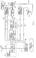
- FIG. 1 is a block diagram of the components of the present invention as installed in a vapour recovery liquid fuel dispensing system.
- a conventional liquid fuel dispenser 10 draws fuel from a reservoir 12 along a liquid inlet line 13 and discharges it through an outlet line 17, typically to a nozzle 15 adapted to fit into the filler pipe of a motor vehicle tank.
- a fuel flow transducer 14 Interposed between the lines 13 and 17 is a fuel flow transducer 14 which measures the liquid flow rate passing through the dispenser 10. This flow rate is conventionally used to determine the amount of fuel sold.
- a signal representing the volumetric liquid flow rate is also fed to a controller 50 along line 18.
- Vapour is retrieved through an orifice at the nozzle 15, shown schematically in Figure 1 as a vapour passage 30 through nozzle 15.
- the vapour line 34 from the vapour passage 30 generally parallels and juxtaposes, in practice, the fuel line 17, the two nozzles 15 shown schematically in Figure 1 in reality being a single nozzle.
- the vapour is induced to move along line 34 by a vapour pump 36 which pumps the vapour from the passage 30 to the reservoir 12 (shown schematically as a second reservoir, but in actuality, the same as the first-mentioned reservoir 12). Within reservoir 12 the vapour may be available for condensation and reuse.
- Upstream of the pump 36 is a vapour pump inlet 35 and downstream is a vapour pump outlet 37.
- the pressures at the inlet and outlet are measured by sensors such as inlet pressure transducer 38 and outlet pressure transducer 40.
- the signals from these sensors are passed along lines 60, 64 to the controller 50.
- the temperature of the liquid fuel in the reservoir 12 is sensed by a temperature sensor 16 which passes a temperature signal along line 68 to the controller 50.
- Other sensor locations may be used, if desired.
- the temperature of the vapour is sensed by a temperature sensor 32, with a corresponding signal being passed along line 66 to the controller 50.
- the vapour temperature may, if desired, be approximated by measuring the ambient temperature.
- the vapour pump 36 is driven by shaft 44 of electric motor 42.
- the speed of the electric motor 42 is transmitted to the vapour pump and directly affects the vapour pump speed.
- a signal of that speed is passed along line 62 back to the controller 50.
- the controller 50 includes vapour recovery control electronics 52 and motor drive electronics 54.
- the vapour recovery control electronics 52 receives the various input signals 60, 62, 64, 66, 68, 18 and outputs a velocity modulation signal 53 to the motor drive electronics 54 which suitably configures the motor velocity modulation signal as an output voltage drive signal 55 to the motor 42.
- the motor drive electronics 54 may modify a DC-type analogue signal to a pulse train.
- the exact configuration of the vapour recovery electronics 52 and motor drive electronics 54 may be selected by those of ordinary skill in the art according to the nature of the various input sensor signals and the motor type.
- the vapour recovery control electronics 52 compares the difference between the inlet and outlet pressure signals 60, 64 as a measure of the actual volumetric flow rate through the vapour pump 36 and compares the so-calculated vapour flow rate with a desired flow rate.
- the desired flow rate may be the actual liquid fuel flow rate represented by signal 18.
- that flow rate is modified to take account of the differences in temperature of the vapour and liquid, as signalled to the vapour recovery control electronics 52 along lines 66, 68, in accordance with principles set forth in U.S. Patent No. 5,156,199 to Hartsell et al, the entire disclosure of which is hereby incorporated herein by reference.
- the desired vapour flow rate may, of course, be determined by other means, provided that it is compared with the ascertained actual flow rate, the actual flow rate being ascertained from the differences in the inlet and outlet pressures across the vapour pump 36.
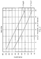
- a graph of a characteristic of a vapour pump 36 illustrates how the difference in the inlet and outlet pressures may be used to give a measure of the flow rate.
- the data recorded in Figure 2 is representative of characteristics of Blackmer Positive Displacement Pump Model VRG 3/4, operating at 2800 rpm. Two plots are shown.
- the ordinate of the graph shows the flow rate through the vapour pump in actual cubic feet per hour.
- the abscissa shows the outlet pressure, such as the signal on line 60, in inches of water.
- the upper plot shows a relationship of these two variables for a constant inlet vacuum of 1" of water, comparable to the signal along line 64.
- the lower plot shows the same relationship for a 10" inlet vacuum.
- the flow rate is almost linearly inversely proportional to the outlet vacuum. In practice, the relationship can be treated as linear.
- the inlet and outlet pressures measured as vacuum levels or otherwise
- vapour pump flow rate measurement can be used to determine if there is a deviation from a desired vapour pump flow rate, and the speed of the motor 42 can be modified to reduce any such discrepancy.
- the discrepancies may arise from various temporary or permanent restrictions or obstructions along the lines 34, 39 from the vapour passage 30 back to the reservoir 12. Prior to the present invention, such aberrations could cause inappropriate vapour pump flow rates which could lead to the release of vapours to the atmosphere, dangerous buildup of oxygen in the reservoir 12, or decreases in the vapour recovery efficiency.
- the motor velocity modulation signal 53 can be increased to speed up the electric motor 42 to compensate for such sensed deficiency in the vapour flow rate.
- the actual motor rate is sensed along line 62. If the flow rate through the vapour pump 36 is sensed as being too high, so that air is being pumped into the reservoir 12, the vapour recovery control electronics can retard the speed of motor 42, to reduce the flow rate through the vapour pump 36.
Landscapes
- Fluid Mechanics (AREA)
- Engineering & Computer Science (AREA)
- Mechanical Engineering (AREA)
- Physics & Mathematics (AREA)
- Vaporization, Distillation, Condensation, Sublimation, And Cold Traps (AREA)
- Loading And Unloading Of Fuel Tanks Or Ships (AREA)
- Waste-Gas Treatment And Other Accessory Devices For Furnaces (AREA)
- Addition Polymer Or Copolymer, Post-Treatments, Or Chemical Modifications (AREA)
- Disintegrating Or Milling (AREA)
- Control Of Positive-Displacement Pumps (AREA)
- Gas Separation By Absorption (AREA)
- Separation, Recovery Or Treatment Of Waste Materials Containing Plastics (AREA)
- Jet Pumps And Other Pumps (AREA)
Abstract
Description
- The present invention relates to improvements in vapour recovery apparatus for liquid fuel dispensers, and an improved method for recovering vapour in liquid fuel dispensers, both particularly, but not exclusively, applicable in the dispensing of fuel to a motor vehicle.
- Many fuel dispensers for the fuelling of vehicles are now equipped with means for recovering vapour displaced by the fuel entering the vehicle tank. Such dispensers are becoming more prevalent with the growing appreciation of the need to reduce environmental pollution, and indeed many existing non-"vapour recovery" dispensers are being retro-fitted with vapour recovery systems.
- Vapour recovery essentially comprises extracting the vapour emanating from the vehicle tank as the fuel is dispensed and returning this vapour via a vapour recovery line to an underground tank, normally with the aid of a pump.
- It is known that the rate of flow of the vapour in the vapour recovery portion of the system should be selected to avoid two undesired conditions. First, a vapour flow rate which is too low will not retrieve all of the vapour, thus permitting pollution to go on. A vapour recovery flow rate which is too high will pull in air, along with the vapour. The oxygen component of the air, if allowed to build to a relatively high level, can cause a dangerously explosive mixture to exist in the fuel reservoir. Accordingly, the vapour flow rate is of critical concern. Several prior endeavors have focused on calculating what the desired flow rate ought to be. For example, U.S. Patent No. 5,040,577 to Pope, the disclosure of which is hereby incorporated by reference, describes a vapour recovery system in which the speed of the vapour recovery pump is set by a microprocessor so its volumetric flow rate matches the volumetric flow rate of the liquid dispenser. In one embodiment, the volumetric flow of the vapour recovery pump is modified so as to maintain an expected pressure at its input.
- In European Patent Application Number 92306271 there is disclosed a system in which the vapour flow rate is modified from the liquid flow rate, to account for thermal expansion or contraction of the vapour caused by heat exchange with the liquid.
- U.S. Patent No. 5,038,838 to Bergamini et al discloses a system in which the vapour pump is continuously controlled to draw in a volumetric quantity of a vapour/air mixture equal to the volumetric quantity of fuel delivered, plus a possible excess of air.
- However, none of the aforementioned systems disclose or suggest how to monitor the actual flow rate through the vapour pump. This is a problem for, unlike a liquid, the vapour is compressible and therefore the volume displaced, for example by a positive displacement pump, is not dependent only on the operation of the pump, but will deviate depending on conditions extemal to the pump.
- Such deviations may be introduced by various aspects of the vapour recovery fuel dispenser system, and may vary from one installation to another. Variations in components such as hose length, the presence of liquid in the vapour line, or dirt/particle deposits on the inside of the vapour lines influence the inlet vacuum and/or discharge pressure. This influence increases or decreases the vacuum and/or discharge pressure, which in turn affects the amount of vapour flow through the vapour recovery system. Other components of the system which might influence the pressure differential across the pump and its resultant flow rate are the presence of hose breakaways, smaller size vapour return piping, and the like.
- Accordingly, there remains a need in the art for an apparatus and method for monitoring the flow rate through the vapour pump and correcting for any discrepancies between a desired and ascertained flow rate.
- According to a first aspect of the present invention there is provided vapour recovery apparatus for pumping recovered vapour in a vapour recovery liquid fuel dispenser including a vapour passage and a vapour pump arranged to pump vapour from the vapour passage through a vapour pump inlet to a vapour pump outlet and having a characteristic that the flow rate through the vapour pump at a given vapour pump operating speed is determinable from the difference between the vapour pump inlet and outlet pressures. Sensors associated with the inlet and outlet are provided to generate signals representative of the inlet and outlet pressures. A controller for the vapour pump is arranged to receive the pressure signals and a desired vapour pump flow rate datum and is adapted to adjust the vapour pump operating speed to reduce any discrepancies between a vapour pump flow rate derived from the pressure signals and the desired vapour pump flow rate datum.
- By employing the present invention it is possible to derive the vapour flow rate without the need for any additional moving components in the system. The use of pressure sensors also avoids any problems with inertia that may be a problem with mechanical flow sensors.
- In a preferred embodiment, the vapour pump has a characteristic that the flow rate through the vapour pump at a given operating speed is inversely proportional to the difference between the vapour pump inlet and outlet pressures.
- Typically, the vapour pump is driven by an electric motor and the controller includes vapour recovery control electronics and motor drive electronics. The electronics receives the desired vapour pump flow rate datum, the pressure signals and a vapour pump speed signal and outputs a motor velocity modulation signal to the motor drive electronics. The motor drive electronics, in turn, outputs a voltage drive signal to the motor.
- The apparatus is useful in a liquid fuel dispenser apparatus adapted to dispense liquid fuel. A transducer associated with the dispenser apparatus generates a liquid fuel flow signal indicative of the rate of liquid fuel flow and applies the liquid fuel flow signal to the controller as the desired vapour pump flow rate datum. Alternatively, the liquid fuel flow signal may pass through an intermediate processor to determine the desired vapour pump flow rate datum. For example, the intermediate processor may modify the liquid fuel flow signal to compensate for thermal contraction or expansion of the vapour arising from temperature differences between the liquid fuel and the vapour.
- According to a second aspect of the invention a method is provided for pumping recovered vapour in a vapour recovery liquid fuel dispenser. The method includes providing a vapour pump having a characteristic that the flow rate through the vapour pump at a given vapour pump operating speed is determinable from the difference between the vapour pump inlet and outlet pressures and pumping vapour with the vapour pump from a vapour passage through a vapour pump inlet to a vapour pump outlet. The pressures at the inlet and outlet of the vapour pump are sensed, and the vapour pump speed is controlled in response to the sensed pressures and a desired vapour pump flow rate. In a presently preferred embodiment, the pump flow rate is inversely proportional to the pressure difference.
- The method preferably includes driving the vapour pump by an electric motor and the controlling step includes controlling the electric motor, such as by outputting a voltage drive signal to the motor.
- The method advantageously includes dispensing liquid fuel at a liquid fuel flow rate and using the liquid fuel flow rate as the desired vapour pump flow rate. Alternatively, the liquid fuel flow rate and the respective liquid fuel and vapour temperatures may be used to derive the desired vapour pump flow rate.
- The invention is useful for the dispensing of volatile liquids generally, where the recovery of the vapours of the liquids is desired. Therefore the invention should be deemed to include methods and apparatus for pumping recovered vapour in a dispenser for other volatile liquids, in addition to liquid fuels.
- One embodiment of the present invention will now be described by way of example only, with reference to the accompanying drawings of which:
- Figure 1 is a block diagram of a vapour recovery fuel dispenser according to a preferred embodiment of the invention; and
- Figure 2 is a graph of the vapour flow rate correlated with the pressure across the vapour pump used in the preferred embodiment.
- Referring now to Figure 1, which is a block diagram of the components of the present invention as installed in a vapour recovery liquid fuel dispensing system. A conventional
liquid fuel dispenser 10 draws fuel from areservoir 12 along aliquid inlet line 13 and discharges it through anoutlet line 17, typically to anozzle 15 adapted to fit into the filler pipe of a motor vehicle tank. Interposed between thelines fuel flow transducer 14 which measures the liquid flow rate passing through thedispenser 10. This flow rate is conventionally used to determine the amount of fuel sold. However, in the present invention, a signal representing the volumetric liquid flow rate is also fed to acontroller 50 along line 18. - Vapour is retrieved through an orifice at the
nozzle 15, shown schematically in Figure 1 as avapour passage 30 throughnozzle 15. Thevapour line 34 from thevapour passage 30 generally parallels and juxtaposes, in practice, thefuel line 17, the twonozzles 15 shown schematically in Figure 1 in reality being a single nozzle. The vapour is induced to move alongline 34 by avapour pump 36 which pumps the vapour from thepassage 30 to the reservoir 12 (shown schematically as a second reservoir, but in actuality, the same as the first-mentioned reservoir 12). Withinreservoir 12 the vapour may be available for condensation and reuse. Upstream of thepump 36 is avapour pump inlet 35 and downstream is avapour pump outlet 37. The pressures at the inlet and outlet are measured by sensors such asinlet pressure transducer 38 andoutlet pressure transducer 40. The signals from these sensors are passed alonglines controller 50. Similarly, the temperature of the liquid fuel in thereservoir 12 is sensed by atemperature sensor 16 which passes a temperature signal alongline 68 to thecontroller 50. Other sensor locations may be used, if desired. The temperature of the vapour is sensed by atemperature sensor 32, with a corresponding signal being passed alongline 66 to thecontroller 50. The vapour temperature may, if desired, be approximated by measuring the ambient temperature. - The
vapour pump 36 is driven byshaft 44 ofelectric motor 42. Thus, the speed of theelectric motor 42 is transmitted to the vapour pump and directly affects the vapour pump speed. A signal of that speed is passed alongline 62 back to thecontroller 50. Thecontroller 50 includes vapourrecovery control electronics 52 andmotor drive electronics 54. The vapourrecovery control electronics 52 receives the various input signals 60, 62, 64, 66, 68, 18 and outputs avelocity modulation signal 53 to themotor drive electronics 54 which suitably configures the motor velocity modulation signal as an outputvoltage drive signal 55 to themotor 42. For example, if themotor 42 is a stepper motor, themotor drive electronics 54 may modify a DC-type analogue signal to a pulse train. The exact configuration of thevapour recovery electronics 52 andmotor drive electronics 54 may be selected by those of ordinary skill in the art according to the nature of the various input sensor signals and the motor type. - In particular, the vapour
recovery control electronics 52 compares the difference between the inlet and outlet pressure signals 60, 64 as a measure of the actual volumetric flow rate through thevapour pump 36 and compares the so-calculated vapour flow rate with a desired flow rate. The desired flow rate may be the actual liquid fuel flow rate represented by signal 18. Preferably, that flow rate is modified to take account of the differences in temperature of the vapour and liquid, as signalled to the vapourrecovery control electronics 52 alonglines - The desired vapour flow rate may, of course, be determined by other means, provided that it is compared with the ascertained actual flow rate, the actual flow rate being ascertained from the differences in the inlet and outlet pressures across the
vapour pump 36. - Referring now to Figure 2, a graph of a characteristic of a
vapour pump 36 illustrates how the difference in the inlet and outlet pressures may be used to give a measure of the flow rate. The data recorded in Figure 2 is representative of characteristics of Blackmer Positive Displacement Pump Model VRG 3/4, operating at 2800 rpm. Two plots are shown. - The ordinate of the graph shows the flow rate through the vapour pump in actual cubic feet per hour. The abscissa shows the outlet pressure, such as the signal on
line 60, in inches of water. The upper plot shows a relationship of these two variables for a constant inlet vacuum of 1" of water, comparable to the signal alongline 64. The lower plot shows the same relationship for a 10" inlet vacuum. As can be seen, for each inlet vacuum, the flow rate is almost linearly inversely proportional to the outlet vacuum. In practice, the relationship can be treated as linear. Thus, by ascertaining the inlet and outlet pressures (measured as vacuum levels or otherwise), the actual flow rate can be derived quite readily using known mathematical techniques. - Since these characteristics will be characteristics of the vapour pump, measuring the inlet and outlet pressure will give a vapour pump flow rate measurement. That calculated measurement can be used to determine if there is a deviation from a desired vapour pump flow rate, and the speed of the
motor 42 can be modified to reduce any such discrepancy. - The discrepancies may arise from various temporary or permanent restrictions or obstructions along the
lines vapour passage 30 back to thereservoir 12. Prior to the present invention, such aberrations could cause inappropriate vapour pump flow rates which could lead to the release of vapours to the atmosphere, dangerous buildup of oxygen in thereservoir 12, or decreases in the vapour recovery efficiency. - In operation, when fuel is to be dispensed through the
outlet nozzle 15, it is drawn from thereservoir 12 alongline 13 and measured in thefuel flow transducer 14. The fuel flow rate in thetransducer 14 is signalled along line 18 to thecontroller 50, along with an indication of the liquid temperature alongline 68. At the same time, the vapour recovery component is started, so that thevapour pump 36 begins drawing vapour from thevapour passage 30 alonglines reservoir 12. The temperature of the vapour or the ambient is signalled alongline 66 to thecontroller 50. The vapourrecovery control electronics 52 of thecontroller 50 outputs to the motor drive electronics 54 a motor orvelocity modulation signal 53, which is selected to have the vapour flow rate match the liquid flow rate through thetransducer 14, as modified to compensate for thermal contraction or expansion of the vapour. If desired, the temperature compensation may be omitted, or other compensations may be included. Themotor drive electronics 54, in turn, shapes that signal and applies a modifiedversion 55 to theelectric motor 42 so that theshaft 44 of themotor 42 drives thevapour pump 36 at the desired speed. The vapourrecovery control electronics 52 also receives the inlet and outlet pressure signals alonglines pump 36 and compare it with the desired vapour recovery flow rate. If the result of that comparison indicates that flow rate is insufficient, the motorvelocity modulation signal 53 can be increased to speed up theelectric motor 42 to compensate for such sensed deficiency in the vapour flow rate. The actual motor rate is sensed alongline 62. If the flow rate through thevapour pump 36 is sensed as being too high, so that air is being pumped into thereservoir 12, the vapour recovery control electronics can retard the speed ofmotor 42, to reduce the flow rate through thevapour pump 36.
Claims (12)
- Vapour recovery apparatus for pumping recovered vapour in a vapour recovery liquid fuel dispenser comprising
a vapour passage (39),
a vapour pump (36) arranged to pump vapour from said vapour passage through a vapour pump inlet (35) to a vapour pump outlet (37) and having a characteristic that the flow rate through the vapour pump (36) at a given vapour pump operating speed is determinable from the difference between the vapour pump inlet and outlet pressures,
sensors (38, 40) associated with said inlet and outlet to generate signals representative of the inlet and outlet pressures, and
a controller (50) for said vapour pump arranged to receive the pressure signals and a desired vapour pump flow rate datum and adapted to adjust the vapour pump operating speed to reduce any discrepancies between a vapour pump flow rate derived from the pressure signals and the desired vapour pump flow rate datum. - Apparatus as claimed in claim 1 wherein said vapour pump has a characteristic that the flow rate through the vapour pump at a given operating speed is inversely proportional to the difference between the vapour pump inlet and outlet pressures.
- Apparatus as claimed in claim 1 or 2 wherein the controller (50) receives a signal indicative of the speed of an electric motor (42) of the vapour recovery pump (36) and controls the speed of the pump dependent on the desired flow rate datum, the pressure signals and the vapour recovery pump speed signal.
- Apparatus as claimed in any preceding claim wherein the desired vapour pump flow rate datum is derived from an electrical signal from a liquid fuel dispenser (10) with which the vapour recovery apparatus is associated, the signal being a liquid fuel flow signal indicative of the rate of liquid fuel flow in the dispenser.
- Apparatus as claimed in claim 4 wherein said controller further comprises means for receiving at least one signal indicative of any temperature differences between the liquid fuel and the vapour, and wherein the controller modifies the liquid fuel flow signal to take account of any such differences in temperature.
- A fuel dispenser comprising vapour recovery apparatus as claimed in any preceding claim.
- A fuel dispenser as claimed in claim 6 wherein the controller controls the vapour pump operating speed, such that any discrepancies between the vapour pump flow rate derived from the pressure signals and the liquid fuel flow rate of the dispenser are reduced.
- A method for pumping recovered vapor in a vapor recovery liquid fuel dispenser comprising
providing a vapor pump (36) having a characteristic that the flow rate through the vapor pump at a given vapor pump operating speed is determinable from the difference between the vapor pump inlet and outlet pressures,
pumping vapor with the vapor pump from a vapor passage (39) through a vapor pump inlet (35) to a vapor pump outlet (37),
sensing the pressures at the inlet and outlet of the vapor pump, and
controlling the vapor pump speed in response to the sensed pressures and a desired vapor pump flow rate to reduce any discrepancies between a vapor pump flow rate derived from the sensed pressures and a desired vapor pump flow rate. - A method as claimed in claim 8 wherein the providing step includes providing a vapor pump that has the characteristic that the flow rate through the vapor pump at a given operating speed is inversely proportional to the difference between the vapor pump inlet and outlet pressures.
- A method as claimed in claim 8 or 9 further comprising determining the speed of the motor in dependence on the sensed pressure, the desired vapour pump flow rate and the determined speed of the motor.
- A method as claimed in claim 8, 9 or 10 further comprising dispensing liquid fuel at a liquid fuel flow rate and using the liquid fuel flow rate as the desired vapour pump flow rate.
- A method as claimed in any one of claims 8 to 10 further comprising determining any difference between the temperature of the liquid and the temperature of the vapour and using the respective liquid fuel and vapour temperatures to derive the desired vapour pump flow rate.
Applications Claiming Priority (2)
| Application Number | Priority Date | Filing Date | Title |
|---|---|---|---|
| US07/968,390 US5269353A (en) | 1992-10-29 | 1992-10-29 | Vapor pump control |
| US968390 | 1992-10-29 |
Publications (2)
| Publication Number | Publication Date |
|---|---|
| EP0595655A1 EP0595655A1 (en) | 1994-05-04 |
| EP0595655B1 true EP0595655B1 (en) | 1996-07-24 |
Family
ID=25514208
Family Applications (1)
| Application Number | Title | Priority Date | Filing Date |
|---|---|---|---|
| EP93308684A Expired - Lifetime EP0595655B1 (en) | 1992-10-29 | 1993-10-29 | Vapour recovery apparatus |
Country Status (10)
| Country | Link |
|---|---|
| US (1) | US5269353A (en) |
| EP (1) | EP0595655B1 (en) |
| AT (1) | ATE140685T1 (en) |
| AU (1) | AU665464B2 (en) |
| DE (1) | DE69303799T2 (en) |
| DK (1) | DK0595655T3 (en) |
| ES (1) | ES2090890T3 (en) |
| GR (1) | GR3021405T3 (en) |
| NO (1) | NO305475B1 (en) |
| NZ (1) | NZ250073A (en) |
Families Citing this family (45)
| Publication number | Priority date | Publication date | Assignee | Title |
|---|---|---|---|---|
| US5345979A (en) * | 1992-10-29 | 1994-09-13 | Gilbacro, Inc. | High efficiency vapor recovery fuel dispensing |
| US5507325A (en) * | 1993-11-17 | 1996-04-16 | Finlayson; Ian M. | Vapor recovery system for fuel dispensers |
| US5452750A (en) * | 1993-12-03 | 1995-09-26 | Gilharco, Inc. | Manually activated vapor valve for gasoline dispensers |
| US5450883A (en) * | 1994-02-07 | 1995-09-19 | Gilbarco, Inc. | System and method for testing for error conditions in a fuel vapor recovery system |
| DE4434216C2 (en) * | 1994-03-19 | 1998-04-09 | Fritz Curtius | Procedure for diagnosing fuel leaks |
| US5602745A (en) * | 1995-01-18 | 1997-02-11 | Gilbarco Inc. | Fuel dispenser electronics design |
| FR2736340B1 (en) * | 1995-07-06 | 1997-08-22 | Janssen Sylvain Jean | CIRCUIT AND SYSTEM FOR RECOVERING HYDROCARBON VAPORS FOR SERVICE STATIONS USING A TWO-STAGE PUMP |
| US5706871A (en) * | 1995-08-15 | 1998-01-13 | Dresser Industries, Inc. | Fluid control apparatus and method |
| US5860457A (en) * | 1995-08-15 | 1999-01-19 | Dresser Industries | Gasoline vapor recovery system and method utilizing vapor detection |
| US5868175A (en) * | 1996-06-28 | 1999-02-09 | Franklin Electric Co., Inc. | Apparatus for recovery of fuel vapor |
| US5832967A (en) * | 1996-08-13 | 1998-11-10 | Dresser Industries, Inc. | Vapor recovery system and method utilizing oxygen sensing |
| US5715875A (en) * | 1996-09-09 | 1998-02-10 | Dover Corporation | Method and apparatus for dry testing vapor recovery systems |
| US5765603A (en) * | 1997-03-14 | 1998-06-16 | Healy Systems, Inc. | Monitoring fuel vapor flow in vapor recovery system |
| US5913343A (en) * | 1997-08-08 | 1999-06-22 | Dresser Industries, Inc. | Vapor recovery system and method |
| US6026866A (en) * | 1997-08-11 | 2000-02-22 | Gilbarco Inc. | Onboard vapor recovery detection nozzle |
| WO1999047453A1 (en) * | 1998-03-20 | 1999-09-23 | Healy Systems, Inc. | Coaxial vapor flow indicator |
| US5988232A (en) | 1998-08-14 | 1999-11-23 | Tokheim Corporation | Vapor recovery system employing oxygen detection |
| NZ337450A (en) * | 1998-08-25 | 2001-01-26 | Marconi Commerce Sys Inc | Fuel delivery system with control system to determine whether vapour recovery is operating outside of acceptable limits |
| DE19850417C2 (en) * | 1998-11-02 | 2002-08-08 | Eppendorf Ag | Electronic dosing device |
| US6338369B1 (en) | 1998-11-09 | 2002-01-15 | Marconi Commerce Systems Inc. | Hydrocarbon vapor sensing |
| US6332483B1 (en) | 1999-03-19 | 2001-12-25 | Healy Systems, Inc. | Coaxial vapor flow indicator with pump speed control |
| FR2791658B1 (en) * | 1999-03-31 | 2001-05-25 | Tokheim Sofitam Sa | INSTALLATION FOR DISPENSING LIQUID HYDROCARBONS PROVIDED WITH A VAPOR RECOVERY MEANS |
| DE59908813D1 (en) * | 1999-08-17 | 2004-04-15 | Jehad Aiysh | Monitoring device for fuel vapor return |
| US6460579B2 (en) | 1999-11-17 | 2002-10-08 | Gilbarco Inc. | Vapor flow and hydrocarbon concentration sensor for improved vapor recovery in fuel dispensers |
| US6418983B1 (en) * | 1999-11-17 | 2002-07-16 | Gilbasco Inc. | Vapor flow and hydrocarbon concentration sensor for improved vapor recovery in fuel dispensers |
| US6712101B1 (en) | 1999-11-17 | 2004-03-30 | Gilbarco Inc. | Hydrocarbon sensor diagnostic method |
| US6386246B2 (en) | 1999-11-17 | 2002-05-14 | Marconi Commerce Systems Inc. | Vapor flow and hydrocarbon concentration sensor for improved vapor recovery in fuel dispensers |
| US6622757B2 (en) | 1999-11-30 | 2003-09-23 | Veeder-Root Company | Fueling system vapor recovery and containment performance monitor and method of operation thereof |
| US6901786B2 (en) * | 1999-11-30 | 2005-06-07 | Veeder-Root Company | Fueling system vapor recovery and containment leak detection system and method |
| US6336479B1 (en) | 2000-02-07 | 2002-01-08 | Marconi Commerce Systems Inc. | Determining vapor recovery in a fueling system |
| US6357493B1 (en) | 2000-10-23 | 2002-03-19 | Marconi Commerce Systems Inc. | Vapor recovery system for a fuel dispenser |
| US6347649B1 (en) | 2000-11-16 | 2002-02-19 | Marconi Commerce Systems Inc. | Pressure sensor for a vapor recovery system |
| FR2823191B1 (en) * | 2001-04-06 | 2003-09-05 | Tokheim Services France | METHOD FOR CONTROLLING THE HYDROCARBON CONTENT OF A CIRCULATING STEAM IN A SYSTEM EQUIPPED WITH A STEAM VAPOR SYSTEM |
| DE10164898B4 (en) * | 2001-04-30 | 2010-09-23 | Berlin Heart Gmbh | Method for controlling a support pump for pulsatile pressure fluid delivery systems |
| AU2003217938A1 (en) * | 2002-03-05 | 2003-09-22 | Veeder-Root Company Inc. | Apparatus and method to control excess pressure in fuel storage containment system at fuel dispensing facilities |
| ITBZ20020010A1 (en) * | 2002-03-11 | 2003-09-11 | Wolftank System Gmbh Srl | CONTROL SYSTEM FOR VAPOR SUCTION SYSTEMS, IN PARTICULAR FOR PETROL DISTRIBUTORS. |
| US7909069B2 (en) * | 2006-05-04 | 2011-03-22 | Veeder-Root Company | System and method for automatically adjusting an ORVR compatible stage II vapor recovery system to maintain a desired air-to-liquid (A/L) ratio |
| US20090242380A1 (en) * | 2008-03-31 | 2009-10-01 | Zebuhr William H | Rotary-Heat-Exchanger Flow Control |
| ES2380518T3 (en) | 2008-05-28 | 2012-05-14 | Franklin Fueling Systems, Inc. | Procedure and apparatus for monitoring a restriction in a phase II fuel vapor recovery system |
| US8191585B2 (en) | 2008-05-28 | 2012-06-05 | Franklin Fueling Systems, Inc. | Method and apparatus for monitoring for a restriction in a stage II fuel vapor recovery system |
| WO2010135224A1 (en) | 2009-05-18 | 2010-11-25 | Franklin Fueling Systems, Inc. | Method and apparatus for detecting a leak in a fuel delivery system |
| WO2011163130A1 (en) * | 2010-06-22 | 2011-12-29 | Franklin Fueling Systems, Inc. | Apparatus and methods for conserving energy in fueling appalications |
| CN104528627B (en) | 2014-12-19 | 2017-10-20 | 华南理工大学 | A kind of self-alignment fuel charger variable frequency oil gas recovery control system of gas liquid ratio and method |
| US20240025726A1 (en) | 2022-07-19 | 2024-01-25 | 7-Eleven, Inc. | Anomaly detection during fuel dispensing operations |
| US11993507B2 (en) | 2022-07-19 | 2024-05-28 | 7-Eleven, Inc. | Anomaly detection and controlling fuel dispensing operations using fuel volume determinations |
Family Cites Families (17)
| Publication number | Priority date | Publication date | Assignee | Title |
|---|---|---|---|---|
| US3713337A (en) * | 1971-02-04 | 1973-01-30 | Daniel Ind Inc | Apparatus and method for automatic differential pressure transducer range changing |
| US3729995A (en) * | 1971-08-26 | 1973-05-01 | Fischer & Porter Co | Pressure and temperature compensation system for flowmeter |
| US4101056A (en) * | 1975-05-27 | 1978-07-18 | George E. Mattimoe | Temperature-compensating petroleum product dispensing unit |
| US4057085A (en) * | 1975-08-20 | 1977-11-08 | International Telephone And Telegraph Corporation | Vapor recovery system |
| US4277832A (en) * | 1979-10-01 | 1981-07-07 | General Electric Company | Fluid flow control system |
| EP0132374B1 (en) * | 1983-07-20 | 1988-01-20 | Tokyo Tatsuno Company Limited | Device for measuring liquid flow volume with temperature compensating |
| DE3512960C2 (en) * | 1985-04-11 | 1987-03-05 | Intra-Automation GmbH Meß- und Regelinstrumente, 4053 Jüchen | Differential pressure flow probe |
| DE3703401A1 (en) * | 1987-02-05 | 1988-08-18 | Al Ko Polar Maschf Gmbh | FAN PART AND METHOD FOR FUNCTIONAL CHECKING THEREOF |
| US4765751A (en) * | 1987-06-29 | 1988-08-23 | United Technologies Corporation | Temperature and pressure probe |
| US4821580A (en) * | 1988-01-27 | 1989-04-18 | Jorritsma Johannes N | Method and apparatus for calculating flow rates through a pumping station |
| IT1228284B (en) * | 1989-01-04 | 1991-06-07 | Nuovo Pignone Spa | IMPROVED SYSTEM FOR SAFE STEAM RECOVERY, PARTICULARLY SUITABLE FOR FUEL DISTRIBUTION SYSTEMS |
| EP0443068A1 (en) * | 1990-02-22 | 1991-08-28 | Scheidt & Bachmann Gmbh | Process and device for removing, during vehicle fuelling, of existing and/or released gases |
| US5040577A (en) * | 1990-05-21 | 1991-08-20 | Gilbarco Inc. | Vapor recovery system for fuel dispenser |
| US5156199A (en) * | 1990-12-11 | 1992-10-20 | Gilbarco, Inc. | Control system for temperature compensated vapor recovery in gasoline dispenser |
| US5195564A (en) * | 1991-04-30 | 1993-03-23 | Dresser Industries, Inc. | Gasoline dispenser with vapor recovery system |
| DE9112594U1 (en) * | 1991-09-25 | 1992-02-20 | Ross Europa GmbH, 6070 Langen | Arrangement for the return of hydrocarbons in fuel filling stations |
| AU648188B2 (en) * | 1992-07-14 | 1994-04-14 | Marconi Commerce Systems Inc. | A liquid delivery system |
-
1992
- 1992-10-29 US US07/968,390 patent/US5269353A/en not_active Expired - Lifetime
-
1993
- 1993-10-27 NZ NZ250073A patent/NZ250073A/en unknown
- 1993-10-27 AU AU50331/93A patent/AU665464B2/en not_active Ceased
- 1993-10-28 NO NO933890A patent/NO305475B1/en not_active IP Right Cessation
- 1993-10-29 AT AT93308684T patent/ATE140685T1/en not_active IP Right Cessation
- 1993-10-29 DE DE69303799T patent/DE69303799T2/en not_active Expired - Fee Related
- 1993-10-29 ES ES93308684T patent/ES2090890T3/en not_active Expired - Lifetime
- 1993-10-29 EP EP93308684A patent/EP0595655B1/en not_active Expired - Lifetime
- 1993-10-29 DK DK93308684T patent/DK0595655T3/en active
-
1996
- 1996-10-22 GR GR960402776T patent/GR3021405T3/en unknown
Also Published As
| Publication number | Publication date |
|---|---|
| NO305475B1 (en) | 1999-06-07 |
| AU665464B2 (en) | 1996-01-04 |
| US5269353A (en) | 1993-12-14 |
| DE69303799D1 (en) | 1996-08-29 |
| DE69303799T2 (en) | 1996-11-28 |
| ES2090890T3 (en) | 1996-10-16 |
| DK0595655T3 (en) | 1996-11-25 |
| GR3021405T3 (en) | 1997-01-31 |
| NO933890D0 (en) | 1993-10-28 |
| EP0595655A1 (en) | 1994-05-04 |
| NZ250073A (en) | 1994-12-22 |
| AU5033193A (en) | 1994-05-12 |
| ATE140685T1 (en) | 1996-08-15 |
| NO933890L (en) | 1994-05-02 |
Similar Documents
| Publication | Publication Date | Title |
|---|---|---|
| EP0595655B1 (en) | Vapour recovery apparatus | |
| EP0577890B1 (en) | A liquid delivery system with vapour recovery | |
| USRE35238E (en) | Vapor recovery system for fuel dispenser | |
| US6899149B1 (en) | Vapor recovery fuel dispenser for multiple hoses | |
| EP1356254B1 (en) | Fluid delivery system | |
| EP1037799B1 (en) | Vapor recovery system employing oxygen detection | |
| EP0461770B1 (en) | Liquid delivery system with vapour and liquid recovering means | |
| JP2789049B2 (en) | Vaporized material safe recovery system | |
| EP0954508B1 (en) | A vapour recovery system for a fuel dispenser | |
| EP2490946B1 (en) | Vapor recovery pump regulation of pressure to maintain air to liquid ratio | |
| US5345979A (en) | High efficiency vapor recovery fuel dispensing | |
| AU2002243724A1 (en) | Fluid delivery system | |
| JPH03505925A (en) | Liquid container with hydrostatic fuel gauge | |
| US6047745A (en) | Process for the recovery of steam emitted in a liquid distribution plant | |
| US6712101B1 (en) | Hydrocarbon sensor diagnostic method | |
| CA2332648C (en) | Apparatus for detecting hydrocarbons using crystal oscillators within fuel dispensers | |
| US20080099097A1 (en) | Method of determining the gas return rate of filling pumps | |
| US6109311A (en) | Method of recovering vapors emitted when a liquid is dispensed | |
| US20070213875A1 (en) | Method of controlling the hydrocarbon content of a vapor circulating in an installation fitted with a vapor intake system | |
| AU648188B2 (en) | A liquid delivery system | |
| JP2023131209A (en) | Fueling device | |
| NZ243803A (en) | Liquid fuel delivery system with controlled vapour recovery |
Legal Events
| Date | Code | Title | Description |
|---|---|---|---|
| PUAI | Public reference made under article 153(3) epc to a published international application that has entered the european phase |
Free format text: ORIGINAL CODE: 0009012 |
|
| AK | Designated contracting states |
Kind code of ref document: A1 Designated state(s): AT BE CH DE DK ES FR GB GR IT LI NL SE |
|
| 17P | Request for examination filed |
Effective date: 19941004 |
|
| 17Q | First examination report despatched |
Effective date: 19950901 |
|
| GRAH | Despatch of communication of intention to grant a patent |
Free format text: ORIGINAL CODE: EPIDOS IGRA |
|
| GRAH | Despatch of communication of intention to grant a patent |
Free format text: ORIGINAL CODE: EPIDOS IGRA |
|
| GRAA | (expected) grant |
Free format text: ORIGINAL CODE: 0009210 |
|
| AK | Designated contracting states |
Kind code of ref document: B1 Designated state(s): AT BE CH DE DK ES FR GB GR IT LI NL SE |
|
| REF | Corresponds to: |
Ref document number: 140685 Country of ref document: AT Date of ref document: 19960815 Kind code of ref document: T |
|
| ITF | It: translation for a ep patent filed | ||
| REG | Reference to a national code |
Ref country code: CH Ref legal event code: NV Representative=s name: JOHN P. MUNZINGER INGENIEUR-CONSEIL |
|
| REF | Corresponds to: |
Ref document number: 69303799 Country of ref document: DE Date of ref document: 19960829 |
|
| ET | Fr: translation filed | ||
| REG | Reference to a national code |
Ref country code: ES Ref legal event code: FG2A Ref document number: 2090890 Country of ref document: ES Kind code of ref document: T3 |
|
| REG | Reference to a national code |
Ref country code: ES Ref legal event code: FG2A Ref document number: 2090890 Country of ref document: ES Kind code of ref document: T3 |
|
| REG | Reference to a national code |
Ref country code: DK Ref legal event code: T3 |
|
| REG | Reference to a national code |
Ref country code: GR Ref legal event code: FG4A Free format text: 3021405 |
|
| PLBE | No opposition filed within time limit |
Free format text: ORIGINAL CODE: 0009261 |
|
| STAA | Information on the status of an ep patent application or granted ep patent |
Free format text: STATUS: NO OPPOSITION FILED WITHIN TIME LIMIT |
|
| 26N | No opposition filed | ||
| PGFP | Annual fee paid to national office [announced via postgrant information from national office to epo] |
Ref country code: SE Payment date: 20001009 Year of fee payment: 8 |
|
| PGFP | Annual fee paid to national office [announced via postgrant information from national office to epo] |
Ref country code: AT Payment date: 20001011 Year of fee payment: 8 |
|
| PGFP | Annual fee paid to national office [announced via postgrant information from national office to epo] |
Ref country code: DK Payment date: 20001012 Year of fee payment: 8 |
|
| PGFP | Annual fee paid to national office [announced via postgrant information from national office to epo] |
Ref country code: NL Payment date: 20001026 Year of fee payment: 8 Ref country code: CH Payment date: 20001026 Year of fee payment: 8 |
|
| PGFP | Annual fee paid to national office [announced via postgrant information from national office to epo] |
Ref country code: GR Payment date: 20001027 Year of fee payment: 8 |
|
| PGFP | Annual fee paid to national office [announced via postgrant information from national office to epo] |
Ref country code: GB Payment date: 20010924 Year of fee payment: 9 |
|
| PGFP | Annual fee paid to national office [announced via postgrant information from national office to epo] |
Ref country code: FR Payment date: 20011010 Year of fee payment: 9 |
|
| PGFP | Annual fee paid to national office [announced via postgrant information from national office to epo] |
Ref country code: ES Payment date: 20011025 Year of fee payment: 9 |
|
| PG25 | Lapsed in a contracting state [announced via postgrant information from national office to epo] |
Ref country code: DK Free format text: LAPSE BECAUSE OF NON-PAYMENT OF DUE FEES Effective date: 20011029 Ref country code: AT Free format text: LAPSE BECAUSE OF NON-PAYMENT OF DUE FEES Effective date: 20011029 |
|
| PG25 | Lapsed in a contracting state [announced via postgrant information from national office to epo] |
Ref country code: SE Free format text: LAPSE BECAUSE OF NON-PAYMENT OF DUE FEES Effective date: 20011030 |
|
| PG25 | Lapsed in a contracting state [announced via postgrant information from national office to epo] |
Ref country code: LI Free format text: LAPSE BECAUSE OF NON-PAYMENT OF DUE FEES Effective date: 20011031 Ref country code: GR Free format text: LAPSE BECAUSE OF NON-PAYMENT OF DUE FEES Effective date: 20011031 Ref country code: CH Free format text: LAPSE BECAUSE OF NON-PAYMENT OF DUE FEES Effective date: 20011031 |
|
| PGFP | Annual fee paid to national office [announced via postgrant information from national office to epo] |
Ref country code: DE Payment date: 20011112 Year of fee payment: 9 |
|
| PGFP | Annual fee paid to national office [announced via postgrant information from national office to epo] |
Ref country code: BE Payment date: 20011214 Year of fee payment: 9 |
|
| REG | Reference to a national code |
Ref country code: GB Ref legal event code: IF02 |
|
| PG25 | Lapsed in a contracting state [announced via postgrant information from national office to epo] |
Ref country code: NL Free format text: LAPSE BECAUSE OF NON-PAYMENT OF DUE FEES Effective date: 20020501 |
|
| EUG | Se: european patent has lapsed |
Ref document number: 93308684.5 |
|
| REG | Reference to a national code |
Ref country code: CH Ref legal event code: PL |
|
| REG | Reference to a national code |
Ref country code: DK Ref legal event code: EBP |
|
| NLV4 | Nl: lapsed or anulled due to non-payment of the annual fee |
Effective date: 20020501 |
|
| PG25 | Lapsed in a contracting state [announced via postgrant information from national office to epo] |
Ref country code: GB Free format text: LAPSE BECAUSE OF NON-PAYMENT OF DUE FEES Effective date: 20021029 |
|
| PG25 | Lapsed in a contracting state [announced via postgrant information from national office to epo] |
Ref country code: ES Free format text: LAPSE BECAUSE OF NON-PAYMENT OF DUE FEES Effective date: 20021030 |
|
| PG25 | Lapsed in a contracting state [announced via postgrant information from national office to epo] |
Ref country code: BE Free format text: LAPSE BECAUSE OF NON-PAYMENT OF DUE FEES Effective date: 20021031 |
|
| BERE | Be: lapsed |
Owner name: *MARCONI COMMERCE SYSTEMS INC. Effective date: 20021031 |
|
| PG25 | Lapsed in a contracting state [announced via postgrant information from national office to epo] |
Ref country code: DE Free format text: LAPSE BECAUSE OF NON-PAYMENT OF DUE FEES Effective date: 20030501 |
|
| GBPC | Gb: european patent ceased through non-payment of renewal fee | ||
| PG25 | Lapsed in a contracting state [announced via postgrant information from national office to epo] |
Ref country code: FR Free format text: LAPSE BECAUSE OF NON-PAYMENT OF DUE FEES Effective date: 20030630 |
|
| REG | Reference to a national code |
Ref country code: FR Ref legal event code: ST |
|
| REG | Reference to a national code |
Ref country code: ES Ref legal event code: FD2A Effective date: 20031112 |
|
| PG25 | Lapsed in a contracting state [announced via postgrant information from national office to epo] |
Ref country code: IT Free format text: LAPSE BECAUSE OF NON-PAYMENT OF DUE FEES;WARNING: LAPSES OF ITALIAN PATENTS WITH EFFECTIVE DATE BEFORE 2007 MAY HAVE OCCURRED AT ANY TIME BEFORE 2007. THE CORRECT EFFECTIVE DATE MAY BE DIFFERENT FROM THE ONE RECORDED. Effective date: 20051029 |