EP0595655B1 - Vorrichtung zur Rückgewinnung von Dämpfen - Google Patents
Vorrichtung zur Rückgewinnung von Dämpfen Download PDFInfo
- Publication number
- EP0595655B1 EP0595655B1 EP93308684A EP93308684A EP0595655B1 EP 0595655 B1 EP0595655 B1 EP 0595655B1 EP 93308684 A EP93308684 A EP 93308684A EP 93308684 A EP93308684 A EP 93308684A EP 0595655 B1 EP0595655 B1 EP 0595655B1
- Authority
- EP
- European Patent Office
- Prior art keywords
- vapour
- pump
- flow rate
- vapor
- liquid fuel
- Prior art date
- Legal status (The legal status is an assumption and is not a legal conclusion. Google has not performed a legal analysis and makes no representation as to the accuracy of the status listed.)
- Expired - Lifetime
Links
Images
Classifications
-
- B—PERFORMING OPERATIONS; TRANSPORTING
- B67—OPENING, CLOSING OR CLEANING BOTTLES, JARS OR SIMILAR CONTAINERS; LIQUID HANDLING
- B67D—DISPENSING, DELIVERING OR TRANSFERRING LIQUIDS, NOT OTHERWISE PROVIDED FOR
- B67D7/00—Apparatus or devices for transferring liquids from bulk storage containers or reservoirs into vehicles or into portable containers, e.g. for retail sale purposes
- B67D7/04—Apparatus or devices for transferring liquids from bulk storage containers or reservoirs into vehicles or into portable containers, e.g. for retail sale purposes for transferring fuels, lubricants or mixed fuels and lubricants
- B67D7/0476—Vapour recovery systems
- B67D7/0478—Vapour recovery systems constructional features or components
- B67D7/048—Vapour flow control means, e.g. valves, pumps
- B67D7/0482—Vapour flow control means, e.g. valves, pumps using pumps driven at different flow rates
- B67D7/0486—Pumps driven in response to electric signals indicative of pressure, temperature or liquid flow
-
- Y—GENERAL TAGGING OF NEW TECHNOLOGICAL DEVELOPMENTS; GENERAL TAGGING OF CROSS-SECTIONAL TECHNOLOGIES SPANNING OVER SEVERAL SECTIONS OF THE IPC; TECHNICAL SUBJECTS COVERED BY FORMER USPC CROSS-REFERENCE ART COLLECTIONS [XRACs] AND DIGESTS
- Y10—TECHNICAL SUBJECTS COVERED BY FORMER USPC
- Y10T—TECHNICAL SUBJECTS COVERED BY FORMER US CLASSIFICATION
- Y10T137/00—Fluid handling
- Y10T137/8593—Systems
- Y10T137/86292—System with plural openings, one a gas vent or access opening
- Y10T137/86324—Tank with gas vent and inlet or outlet
Definitions
- the present invention relates to improvements in vapour recovery apparatus for liquid fuel dispensers, and an improved method for recovering vapour in liquid fuel dispensers, both particularly, but not exclusively, applicable in the dispensing of fuel to a motor vehicle.
- Vapour recovery essentially comprises extracting the vapour emanating from the vehicle tank as the fuel is dispensed and returning this vapour via a vapour recovery line to an underground tank, normally with the aid of a pump.
- the rate of flow of the vapour in the vapour recovery portion of the system should be selected to avoid two undesired conditions.
- a vapour flow rate which is too low will not retrieve all of the vapour, thus permitting pollution to go on.
- a vapour recovery flow rate which is too high will pull in air, along with the vapour.
- the oxygen component of the air if allowed to build to a relatively high level, can cause a dangerously explosive mixture to exist in the fuel reservoir. Accordingly, the vapour flow rate is of critical concern.
- U.S. Patent No. 5,038,838 to Bergamini et al discloses a system in which the vapour pump is continuously controlled to draw in a volumetric quantity of a vapour/air mixture equal to the volumetric quantity of fuel delivered, plus a possible excess of air.
- vapour pump is compressible and therefore the volume displaced, for example by a positive displacement pump, is not dependent only on the operation of the pump, but will deviate depending on conditions extemal to the pump.
- Such deviations may be introduced by various aspects of the vapour recovery fuel dispenser system, and may vary from one installation to another. Variations in components such as hose length, the presence of liquid in the vapour line, or dirt/particle deposits on the inside of the vapour lines influence the inlet vacuum and/or discharge pressure. This influence increases or decreases the vacuum and/or discharge pressure, which in turn affects the amount of vapour flow through the vapour recovery system. Other components of the system which might influence the pressure differential across the pump and its resultant flow rate are the presence of hose breakaways, smaller size vapour return piping, and the like.
- vapour recovery apparatus for pumping recovered vapour in a vapour recovery liquid fuel dispenser including a vapour passage and a vapour pump arranged to pump vapour from the vapour passage through a vapour pump inlet to a vapour pump outlet and having a characteristic that the flow rate through the vapour pump at a given vapour pump operating speed is determinable from the difference between the vapour pump inlet and outlet pressures.
- Sensors associated with the inlet and outlet are provided to generate signals representative of the inlet and outlet pressures.
- a controller for the vapour pump is arranged to receive the pressure signals and a desired vapour pump flow rate datum and is adapted to adjust the vapour pump operating speed to reduce any discrepancies between a vapour pump flow rate derived from the pressure signals and the desired vapour pump flow rate datum.
- the vapour pump has a characteristic that the flow rate through the vapour pump at a given operating speed is inversely proportional to the difference between the vapour pump inlet and outlet pressures.
- the vapour pump is driven by an electric motor and the controller includes vapour recovery control electronics and motor drive electronics.
- the electronics receives the desired vapour pump flow rate datum, the pressure signals and a vapour pump speed signal and outputs a motor velocity modulation signal to the motor drive electronics.
- the motor drive electronics outputs a voltage drive signal to the motor.
- the apparatus is useful in a liquid fuel dispenser apparatus adapted to dispense liquid fuel.
- a transducer associated with the dispenser apparatus generates a liquid fuel flow signal indicative of the rate of liquid fuel flow and applies the liquid fuel flow signal to the controller as the desired vapour pump flow rate datum.
- the liquid fuel flow signal may pass through an intermediate processor to determine the desired vapour pump flow rate datum.
- the intermediate processor may modify the liquid fuel flow signal to compensate for thermal contraction or expansion of the vapour arising from temperature differences between the liquid fuel and the vapour.
- the method preferably includes driving the vapour pump by an electric motor and the controlling step includes controlling the electric motor, such as by outputting a voltage drive signal to the motor.
- the method advantageously includes dispensing liquid fuel at a liquid fuel flow rate and using the liquid fuel flow rate as the desired vapour pump flow rate.
- the liquid fuel flow rate and the respective liquid fuel and vapour temperatures may be used to derive the desired vapour pump flow rate.
- the invention is useful for the dispensing of volatile liquids generally, where the recovery of the vapours of the liquids is desired. Therefore the invention should be deemed to include methods and apparatus for pumping recovered vapour in a dispenser for other volatile liquids, in addition to liquid fuels.
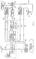
- FIG. 1 is a block diagram of the components of the present invention as installed in a vapour recovery liquid fuel dispensing system.
- a conventional liquid fuel dispenser 10 draws fuel from a reservoir 12 along a liquid inlet line 13 and discharges it through an outlet line 17, typically to a nozzle 15 adapted to fit into the filler pipe of a motor vehicle tank.
- a fuel flow transducer 14 Interposed between the lines 13 and 17 is a fuel flow transducer 14 which measures the liquid flow rate passing through the dispenser 10. This flow rate is conventionally used to determine the amount of fuel sold.
- a signal representing the volumetric liquid flow rate is also fed to a controller 50 along line 18.
- Vapour is retrieved through an orifice at the nozzle 15, shown schematically in Figure 1 as a vapour passage 30 through nozzle 15.
- the vapour line 34 from the vapour passage 30 generally parallels and juxtaposes, in practice, the fuel line 17, the two nozzles 15 shown schematically in Figure 1 in reality being a single nozzle.
- the vapour is induced to move along line 34 by a vapour pump 36 which pumps the vapour from the passage 30 to the reservoir 12 (shown schematically as a second reservoir, but in actuality, the same as the first-mentioned reservoir 12). Within reservoir 12 the vapour may be available for condensation and reuse.
- Upstream of the pump 36 is a vapour pump inlet 35 and downstream is a vapour pump outlet 37.
- the pressures at the inlet and outlet are measured by sensors such as inlet pressure transducer 38 and outlet pressure transducer 40.
- the signals from these sensors are passed along lines 60, 64 to the controller 50.
- the temperature of the liquid fuel in the reservoir 12 is sensed by a temperature sensor 16 which passes a temperature signal along line 68 to the controller 50.
- Other sensor locations may be used, if desired.
- the temperature of the vapour is sensed by a temperature sensor 32, with a corresponding signal being passed along line 66 to the controller 50.
- the vapour temperature may, if desired, be approximated by measuring the ambient temperature.
- the vapour pump 36 is driven by shaft 44 of electric motor 42.
- the speed of the electric motor 42 is transmitted to the vapour pump and directly affects the vapour pump speed.
- a signal of that speed is passed along line 62 back to the controller 50.
- the controller 50 includes vapour recovery control electronics 52 and motor drive electronics 54.
- the vapour recovery control electronics 52 receives the various input signals 60, 62, 64, 66, 68, 18 and outputs a velocity modulation signal 53 to the motor drive electronics 54 which suitably configures the motor velocity modulation signal as an output voltage drive signal 55 to the motor 42.
- the motor drive electronics 54 may modify a DC-type analogue signal to a pulse train.
- the exact configuration of the vapour recovery electronics 52 and motor drive electronics 54 may be selected by those of ordinary skill in the art according to the nature of the various input sensor signals and the motor type.
- the vapour recovery control electronics 52 compares the difference between the inlet and outlet pressure signals 60, 64 as a measure of the actual volumetric flow rate through the vapour pump 36 and compares the so-calculated vapour flow rate with a desired flow rate.
- the desired flow rate may be the actual liquid fuel flow rate represented by signal 18.
- that flow rate is modified to take account of the differences in temperature of the vapour and liquid, as signalled to the vapour recovery control electronics 52 along lines 66, 68, in accordance with principles set forth in U.S. Patent No. 5,156,199 to Hartsell et al, the entire disclosure of which is hereby incorporated herein by reference.
- the desired vapour flow rate may, of course, be determined by other means, provided that it is compared with the ascertained actual flow rate, the actual flow rate being ascertained from the differences in the inlet and outlet pressures across the vapour pump 36.
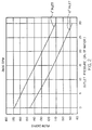
- a graph of a characteristic of a vapour pump 36 illustrates how the difference in the inlet and outlet pressures may be used to give a measure of the flow rate.
- the data recorded in Figure 2 is representative of characteristics of Blackmer Positive Displacement Pump Model VRG 3/4, operating at 2800 rpm. Two plots are shown.
- the ordinate of the graph shows the flow rate through the vapour pump in actual cubic feet per hour.
- the abscissa shows the outlet pressure, such as the signal on line 60, in inches of water.
- the upper plot shows a relationship of these two variables for a constant inlet vacuum of 1" of water, comparable to the signal along line 64.
- the lower plot shows the same relationship for a 10" inlet vacuum.
- the flow rate is almost linearly inversely proportional to the outlet vacuum. In practice, the relationship can be treated as linear.
- the inlet and outlet pressures measured as vacuum levels or otherwise
- vapour pump flow rate measurement can be used to determine if there is a deviation from a desired vapour pump flow rate, and the speed of the motor 42 can be modified to reduce any such discrepancy.
- the discrepancies may arise from various temporary or permanent restrictions or obstructions along the lines 34, 39 from the vapour passage 30 back to the reservoir 12. Prior to the present invention, such aberrations could cause inappropriate vapour pump flow rates which could lead to the release of vapours to the atmosphere, dangerous buildup of oxygen in the reservoir 12, or decreases in the vapour recovery efficiency.
- the motor velocity modulation signal 53 can be increased to speed up the electric motor 42 to compensate for such sensed deficiency in the vapour flow rate.
- the actual motor rate is sensed along line 62. If the flow rate through the vapour pump 36 is sensed as being too high, so that air is being pumped into the reservoir 12, the vapour recovery control electronics can retard the speed of motor 42, to reduce the flow rate through the vapour pump 36.
Landscapes
- Physics & Mathematics (AREA)
- Fluid Mechanics (AREA)
- Engineering & Computer Science (AREA)
- Mechanical Engineering (AREA)
- Loading And Unloading Of Fuel Tanks Or Ships (AREA)
- Vaporization, Distillation, Condensation, Sublimation, And Cold Traps (AREA)
- Waste-Gas Treatment And Other Accessory Devices For Furnaces (AREA)
- Addition Polymer Or Copolymer, Post-Treatments, Or Chemical Modifications (AREA)
- Disintegrating Or Milling (AREA)
- Control Of Positive-Displacement Pumps (AREA)
- Separation, Recovery Or Treatment Of Waste Materials Containing Plastics (AREA)
- Jet Pumps And Other Pumps (AREA)
- Gas Separation By Absorption (AREA)
Claims (12)
- Dampfrückgewinnungsvorrichtung zum Pumpen rückgewonnenen Dampfes in einer Dampfrückgewinnungsflüssigkraftstoffabgabevorrichtung mit
einem Dampfdurchgang (39),
einer Dampfpumpe (36), die eingerichtet ist, Dampf von dem Dampfdurchgang durch einen Dampfpumpeneinlaß (35) zu einem Dampfpumpenauslaß (37) zu pumpen, und eine Charakteristik aufweist, daß die Flußrate durch die Dampfpumpe (36) bei einer gegebenen Dampfpumpenarbeitsgeschwindigkeit aus der Differenz zwischen den Dampfpumpeneinlaß- und -auslaßdrücken bestimmbar ist,
Sensoren (38, 40), die dem Einlaß und dem Auslaß zugeordnet sind, um Signale zu generieren, die die Einlaß- und Auslaßdrücke darstellen, und
einer Steuerungsvorrichtung (50) für die Dampfpumpe, die eingerichtet ist, die Drucksignale und ein gewünschtes Dampfpumpenflußratendatenelement zu empfangen, und ausgelegt ist, die Dampfpumpenarbeitsgeschwindigkeit einzustellen, um jegliche Diskrepanzen zwischen einer Dampfpumpenflußrate, die von den Drucksignalen abgeleitet ist, und dem gewünschten Dampfpumpenflußratendatenelement zu reduzieren. - Vorrichtung wie in Anspruch 1 beansprucht, worin die Dampfpumpe eine Charakteristik aufweist, daß die Flußrate durch die Dampfpumpe bei einer gegebenen Arbeitsgeschwindigkeit umgekehrt proportional zu der Differenz zwischen den Dampfpumpeneinlaß- und -auslaßdrücken ist.
- Vorrichtung wie in Anspruch 1 oder 2 beansprucht, worin die Steuerungsvorrichtung (50) ein Signal empfängt, das die Geschwindigkeit eines Elektromotors (42) der Dampfrückgewinnungspumpe (36) anzeigt, und die Geschwindigkeit der Pumpe abhängig von dem gewünschten Flußratendatenelement, der Drucksignale und dem Dampfrückgewinnungspumpengeschwindigkeitssignal steuert.
- Vorrichtung wie in einem der vorhergehenden Ansprüche beansprucht, worin das gewünschte Dampfpumpenflußratendatenelement von einem elektrischen Signal von einer Flüssigkraftstoffabgabevorrichtung (10) abgeleitet ist, welcher die Dampfrückgewinnungsvorrichtung zugeordnet ist, wobei das Signal ein Flüssigkraftstoffflußsignal ist, das die Flüssigkraftstoffflußrate in der Abgabevorrichtung anzeigt.
- Vorrichtung wie in Anspruch 4 beansprucht, worin die Steuerungsvorrichtung weiter Mittel zum Empfangen wenigstens eines Signals umfaßt, das jegliche Temperaturdifferenzen zwischen dem Flüssigkraftstoff und dem Dampf anzeigt, und worin die Steuerungsvorrichtung das Flüssigkraftstoffflußsignal modifiziert, um jegliche derartige Differenzen in der Temperatur zu berücksichtigen.
- Eine Kraftstoffabgabevorrichtung mit einer Dampfrückgewinnungsvorrichtung wie in einem der vorhergehenden Ansprüche beansprucht.
- Eine Kraftstoffabgabevorrichtung wie in Anspruch 6 beansprucht, worin die Steuerungsvorrichtung die Dampfpumpenarbeitsgeschwindigkeit steuert, so daß jegliche Diskrepanzen zwischen der Dampfpumpenflußrate, die von den Drucksignalen abgeleitet ist, und der Flüssigkraftstoffflußrate der Abgabevorrichtung reduziert sind.
- Ein Verfahren zum Pumpen rückgewonnenen Dampfes in einer Dampfrückgewinnungsflüssigkraftstoffabgabevorrichtung mit den Schritten, daß
eine Dampfpumpe (36) bereitgestellt wird, die eine Charakteristik aufweist, daß die Flußrate durch die Dampfpumpe bei einer gegebenen Dampfpumpenarbeitsgeschwindigkeit aus der Differenz zwischen den Dampfpumpeneinlaß- und -auslaßdrücken bestimmbar ist,
Dampf mit der Dampfpumpe von einem Dampfdurchgang (39) durch einen Dampfpumpeneinlaß (35) zu einem Dampfpumpenauslaß (37) gepumpt wird,
die Drücke am Einlaß und Auslaß der Dampfpumpe wahrgenommen werden, und
die Dampfpumpengeschwindigkeit in Abhängigkeit von den wahrgenommenen Drücken und einer gewünschten Dampfpumpenflußrate gesteuert wird, um jegliche Diskrepanzen zwischen einer Dampfpumpenflußrate zu kompensieren, die von den wahrgenommenen Drücken und einer gewünschten Dampfpumpenflußrate abgeleitet wird. - Ein Verfahren wie in Anspruch 8 beansprucht, worin der Bereitstellungsschritt umfaßt, daß eine Dampfpumpe vorgesehen wird, die die Charakteristik aufweist, daß die Flußrate durch die Dampfpumpe bei einer gegebenen Arbeitsgeschwindigkeit umgekehrt proportional zu der Differenz zwischen den Dampfpumpeneinlaß- und -auslaßdrücken ist.
- Ein Verfahren wie in Anspruch 8 oder 9 beansprucht, welches weiter umfaßt, daß die Geschwindigkeit des Motors in Abhängigkeit von dem wahrgenommenen Druck, der gewünschten Dampfpumpenflußrate und der bestimmten Geschwindigkeit des Motors bestimmt wird.
- Ein Verfahren wie in Anspruch 8, 9 oder 10 beansprucht, welches weiter umfaßt, daß Flüssigkraftstoff mit einer Flüssigkraftstoffflußrate abgegeben wird und die Flüssigkraftstoffflußrate als die gewünschte Dampfpumpenflußrate verwendet wird.
- Ein Verfahren wie in einem der Ansprüche 8 bis 10 beansprucht, welches weiter umfaßt, daß jegliche Differenz zwischen der Temperatur der Flüssigkeit und der Umgebung des Dampfes bestimmt wird und die jeweiligen Flüssigkraftstoff- und Dampftemperaturen verwendet werden, um die gewünschte Dampfpumpenflußrate abzuleiten.
Applications Claiming Priority (2)
| Application Number | Priority Date | Filing Date | Title |
|---|---|---|---|
| US968390 | 1992-10-29 | ||
| US07/968,390 US5269353A (en) | 1992-10-29 | 1992-10-29 | Vapor pump control |
Publications (2)
| Publication Number | Publication Date |
|---|---|
| EP0595655A1 EP0595655A1 (de) | 1994-05-04 |
| EP0595655B1 true EP0595655B1 (de) | 1996-07-24 |
Family
ID=25514208
Family Applications (1)
| Application Number | Title | Priority Date | Filing Date |
|---|---|---|---|
| EP93308684A Expired - Lifetime EP0595655B1 (de) | 1992-10-29 | 1993-10-29 | Vorrichtung zur Rückgewinnung von Dämpfen |
Country Status (10)
| Country | Link |
|---|---|
| US (1) | US5269353A (de) |
| EP (1) | EP0595655B1 (de) |
| AT (1) | ATE140685T1 (de) |
| AU (1) | AU665464B2 (de) |
| DE (1) | DE69303799T2 (de) |
| DK (1) | DK0595655T3 (de) |
| ES (1) | ES2090890T3 (de) |
| GR (1) | GR3021405T3 (de) |
| NO (1) | NO305475B1 (de) |
| NZ (1) | NZ250073A (de) |
Families Citing this family (48)
| Publication number | Priority date | Publication date | Assignee | Title |
|---|---|---|---|---|
| US5345979A (en) * | 1992-10-29 | 1994-09-13 | Gilbacro, Inc. | High efficiency vapor recovery fuel dispensing |
| US5507325A (en) * | 1993-11-17 | 1996-04-16 | Finlayson; Ian M. | Vapor recovery system for fuel dispensers |
| US5452750A (en) * | 1993-12-03 | 1995-09-26 | Gilharco, Inc. | Manually activated vapor valve for gasoline dispensers |
| US5450883A (en) * | 1994-02-07 | 1995-09-19 | Gilbarco, Inc. | System and method for testing for error conditions in a fuel vapor recovery system |
| DE4434216C2 (de) * | 1994-03-19 | 1998-04-09 | Fritz Curtius | Verfahren zur Diagnose von Kraftstoffleckagen |
| US5602745A (en) * | 1995-01-18 | 1997-02-11 | Gilbarco Inc. | Fuel dispenser electronics design |
| FR2736340B1 (fr) * | 1995-07-06 | 1997-08-22 | Janssen Sylvain Jean | Circuit et systeme de recuperation de vapeurs d'hydrocarbures pour stations service usage d'un pompage a deux etages |
| US5860457A (en) * | 1995-08-15 | 1999-01-19 | Dresser Industries | Gasoline vapor recovery system and method utilizing vapor detection |
| US5706871A (en) * | 1995-08-15 | 1998-01-13 | Dresser Industries, Inc. | Fluid control apparatus and method |
| US5868175A (en) * | 1996-06-28 | 1999-02-09 | Franklin Electric Co., Inc. | Apparatus for recovery of fuel vapor |
| US5832967A (en) * | 1996-08-13 | 1998-11-10 | Dresser Industries, Inc. | Vapor recovery system and method utilizing oxygen sensing |
| US5715875A (en) * | 1996-09-09 | 1998-02-10 | Dover Corporation | Method and apparatus for dry testing vapor recovery systems |
| US5765603A (en) * | 1997-03-14 | 1998-06-16 | Healy Systems, Inc. | Monitoring fuel vapor flow in vapor recovery system |
| US5913343A (en) * | 1997-08-08 | 1999-06-22 | Dresser Industries, Inc. | Vapor recovery system and method |
| US6026866A (en) * | 1997-08-11 | 2000-02-22 | Gilbarco Inc. | Onboard vapor recovery detection nozzle |
| EP1105343A4 (de) | 1998-03-20 | 2002-01-02 | Healy Systems Inc | Dampf-durchflussanzeigevorrichtung für gleichachsige leitungen |
| US5988232A (en) | 1998-08-14 | 1999-11-23 | Tokheim Corporation | Vapor recovery system employing oxygen detection |
| AU752463B2 (en) * | 1998-08-25 | 2002-09-19 | Marconi Commerce Systems Inc. | Fuel delivery system |
| DE19850417C2 (de) * | 1998-11-02 | 2002-08-08 | Eppendorf Ag | Elektronische Dosiervorrichtung |
| US6338369B1 (en) | 1998-11-09 | 2002-01-15 | Marconi Commerce Systems Inc. | Hydrocarbon vapor sensing |
| US6332483B1 (en) | 1999-03-19 | 2001-12-25 | Healy Systems, Inc. | Coaxial vapor flow indicator with pump speed control |
| FR2791658B1 (fr) * | 1999-03-31 | 2001-05-25 | Tokheim Sofitam Sa | Installation de distribution d'hydrocarbures liquides equipee d'un moyen de recuperation des vapeurs |
| DE59908813D1 (de) * | 1999-08-17 | 2004-04-15 | Jehad Aiysh | Überwachungseinrichtung für die Kraftstoffdampfrückführung |
| US6712101B1 (en) | 1999-11-17 | 2004-03-30 | Gilbarco Inc. | Hydrocarbon sensor diagnostic method |
| US6386246B2 (en) | 1999-11-17 | 2002-05-14 | Marconi Commerce Systems Inc. | Vapor flow and hydrocarbon concentration sensor for improved vapor recovery in fuel dispensers |
| US6418983B1 (en) | 1999-11-17 | 2002-07-16 | Gilbasco Inc. | Vapor flow and hydrocarbon concentration sensor for improved vapor recovery in fuel dispensers |
| US6460579B2 (en) | 1999-11-17 | 2002-10-08 | Gilbarco Inc. | Vapor flow and hydrocarbon concentration sensor for improved vapor recovery in fuel dispensers |
| US6622757B2 (en) | 1999-11-30 | 2003-09-23 | Veeder-Root Company | Fueling system vapor recovery and containment performance monitor and method of operation thereof |
| US6901786B2 (en) * | 1999-11-30 | 2005-06-07 | Veeder-Root Company | Fueling system vapor recovery and containment leak detection system and method |
| US6336479B1 (en) | 2000-02-07 | 2002-01-08 | Marconi Commerce Systems Inc. | Determining vapor recovery in a fueling system |
| US6357493B1 (en) | 2000-10-23 | 2002-03-19 | Marconi Commerce Systems Inc. | Vapor recovery system for a fuel dispenser |
| US6347649B1 (en) | 2000-11-16 | 2002-02-19 | Marconi Commerce Systems Inc. | Pressure sensor for a vapor recovery system |
| FR2823191B1 (fr) * | 2001-04-06 | 2003-09-05 | Tokheim Services France | Procede de controle de la teneur en hydrocarbures d'une vapeur circulant dans une installation equipee d'un systeme d'aspiration de vapeur |
| DE10164898B4 (de) * | 2001-04-30 | 2010-09-23 | Berlin Heart Gmbh | Verfahren zur Regelung einer Unterstützungspumpe für Fluidfördersysteme mit pulsatilem Druck |
| WO2003076329A1 (en) * | 2002-03-05 | 2003-09-18 | Veeder-Root Company Inc. | Apparatus and method to control excess pressure in fuel storage containment system at fuel dispensing facilities |
| ITBZ20020010A1 (it) * | 2002-03-11 | 2003-09-11 | Wolftank System Gmbh Srl | Impianto di controllo per sistemi di aspirazione vapori, in particolare per distributori di benzina. |
| US7909069B2 (en) | 2006-05-04 | 2011-03-22 | Veeder-Root Company | System and method for automatically adjusting an ORVR compatible stage II vapor recovery system to maintain a desired air-to-liquid (A/L) ratio |
| US20090242380A1 (en) * | 2008-03-31 | 2009-10-01 | Zebuhr William H | Rotary-Heat-Exchanger Flow Control |
| US8402817B2 (en) * | 2008-05-28 | 2013-03-26 | Franklin Fueling Systems, Inc. | Method and apparatus for monitoring for leaks in a stage II fuel vapor recovery system |
| ATE539999T1 (de) | 2008-05-28 | 2012-01-15 | Franklin Fueling Systems Inc | Verfahren und vorrichtung zur überwachung von einschränkungen in einem stufe-ii-brennstoff- dampfgewinnungssystem |
| RU2536093C2 (ru) | 2009-05-18 | 2014-12-20 | Франклин Фьюэлинг Системз, Инк. | Способ и устройство для обнаружения утечки в системе подачи топлива |
| US9249790B2 (en) | 2010-06-22 | 2016-02-02 | Franklin Fueling Systems, Inc. | Apparatus and methods for conserving energy in fueling applications |
| CN104528627B (zh) * | 2014-12-19 | 2017-10-20 | 华南理工大学 | 一种气液比自校准的加油机变频油气回收控制系统及方法 |
| JP7622675B2 (ja) * | 2022-03-09 | 2025-01-28 | 株式会社タツノ | 給油装置 |
| US11993507B2 (en) | 2022-07-19 | 2024-05-28 | 7-Eleven, Inc. | Anomaly detection and controlling fuel dispensing operations using fuel volume determinations |
| US12421100B2 (en) | 2022-07-19 | 2025-09-23 | 7-Eleven, Inc. | Anomaly detection and controlling fuel dispensing operations using fuel volume determinations |
| US20240025726A1 (en) | 2022-07-19 | 2024-01-25 | 7-Eleven, Inc. | Anomaly detection during fuel dispensing operations |
| EP4558447A1 (de) | 2022-07-19 | 2025-05-28 | 7-Eleven, Inc. | Anomaliedetektion während kraftstoffabgabeoperationen |
Family Cites Families (17)
| Publication number | Priority date | Publication date | Assignee | Title |
|---|---|---|---|---|
| US3713337A (en) * | 1971-02-04 | 1973-01-30 | Daniel Ind Inc | Apparatus and method for automatic differential pressure transducer range changing |
| US3729995A (en) * | 1971-08-26 | 1973-05-01 | Fischer & Porter Co | Pressure and temperature compensation system for flowmeter |
| US4101056A (en) * | 1975-05-27 | 1978-07-18 | George E. Mattimoe | Temperature-compensating petroleum product dispensing unit |
| US4057085A (en) * | 1975-08-20 | 1977-11-08 | International Telephone And Telegraph Corporation | Vapor recovery system |
| US4277832A (en) * | 1979-10-01 | 1981-07-07 | General Electric Company | Fluid flow control system |
| DE3468943D1 (en) * | 1983-07-20 | 1988-02-25 | Tokyo Tatsuno Kk | Device for measuring liquid flow volume with temperature compensating |
| DE3512960C2 (de) * | 1985-04-11 | 1987-03-05 | Intra-Automation GmbH Meß- und Regelinstrumente, 4053 Jüchen | Differenzdruckströmungssonde |
| DE3703401A1 (de) * | 1987-02-05 | 1988-08-18 | Al Ko Polar Maschf Gmbh | Ventilatorteil sowie verfahren zur funktionskontrolle desselben |
| US4765751A (en) * | 1987-06-29 | 1988-08-23 | United Technologies Corporation | Temperature and pressure probe |
| US4821580A (en) * | 1988-01-27 | 1989-04-18 | Jorritsma Johannes N | Method and apparatus for calculating flow rates through a pumping station |
| IT1228284B (it) * | 1989-01-04 | 1991-06-07 | Nuovo Pignone Spa | Sistema perfezionato per un sicuro recupero vapori, particolarmente adatto per impianti di distribuzione carburanti |
| EP0443068A1 (de) * | 1990-02-22 | 1991-08-28 | Scheidt & Bachmann Gmbh | Verfahren und Vorrichtung zur Entsorgung der beim Betanken eines Fahrzeugs mit Kraftstoff freiwerdenden und/oder vorhandenen Gase |
| US5040577A (en) * | 1990-05-21 | 1991-08-20 | Gilbarco Inc. | Vapor recovery system for fuel dispenser |
| US5156199A (en) * | 1990-12-11 | 1992-10-20 | Gilbarco, Inc. | Control system for temperature compensated vapor recovery in gasoline dispenser |
| US5195564A (en) * | 1991-04-30 | 1993-03-23 | Dresser Industries, Inc. | Gasoline dispenser with vapor recovery system |
| DE9112594U1 (de) * | 1991-09-25 | 1992-02-20 | Ross Europa GmbH, 6070 Langen | Anordnung zum Rückführen von Kohlenwasserstoffen bei Kraftstoffbetankungsanlagen |
| AU648188B2 (en) * | 1992-07-14 | 1994-04-14 | Marconi Commerce Systems Inc. | A liquid delivery system |
-
1992
- 1992-10-29 US US07/968,390 patent/US5269353A/en not_active Expired - Lifetime
-
1993
- 1993-10-27 NZ NZ250073A patent/NZ250073A/en unknown
- 1993-10-27 AU AU50331/93A patent/AU665464B2/en not_active Ceased
- 1993-10-28 NO NO933890A patent/NO305475B1/no not_active IP Right Cessation
- 1993-10-29 EP EP93308684A patent/EP0595655B1/de not_active Expired - Lifetime
- 1993-10-29 ES ES93308684T patent/ES2090890T3/es not_active Expired - Lifetime
- 1993-10-29 DK DK93308684T patent/DK0595655T3/da active
- 1993-10-29 DE DE69303799T patent/DE69303799T2/de not_active Expired - Fee Related
- 1993-10-29 AT AT93308684T patent/ATE140685T1/de not_active IP Right Cessation
-
1996
- 1996-10-22 GR GR960402776T patent/GR3021405T3/el unknown
Also Published As
| Publication number | Publication date |
|---|---|
| AU5033193A (en) | 1994-05-12 |
| NO933890D0 (no) | 1993-10-28 |
| GR3021405T3 (en) | 1997-01-31 |
| DK0595655T3 (da) | 1996-11-25 |
| AU665464B2 (en) | 1996-01-04 |
| US5269353A (en) | 1993-12-14 |
| NO933890L (no) | 1994-05-02 |
| DE69303799T2 (de) | 1996-11-28 |
| DE69303799D1 (de) | 1996-08-29 |
| NZ250073A (en) | 1994-12-22 |
| ATE140685T1 (de) | 1996-08-15 |
| NO305475B1 (no) | 1999-06-07 |
| ES2090890T3 (es) | 1996-10-16 |
| EP0595655A1 (de) | 1994-05-04 |
Similar Documents
| Publication | Publication Date | Title |
|---|---|---|
| EP0595655B1 (de) | Vorrichtung zur Rückgewinnung von Dämpfen | |
| EP0577890B1 (de) | Flüssigkeitabgabevorrichtung mit Dampfrückgewinnung | |
| USRE35238E (en) | Vapor recovery system for fuel dispenser | |
| US6899149B1 (en) | Vapor recovery fuel dispenser for multiple hoses | |
| EP1037799B1 (de) | System zur dampfrückgewinnung mit sauerstoffsensor | |
| EP0461770B1 (de) | Flüssigkeitsabgabesystem mit Dampf- und Flüssigkeitsrückgewinnung | |
| AU2002243724B2 (en) | Fluid delivery system | |
| JP2789049B2 (ja) | 気化物質安全回収システム | |
| EP0595656B1 (de) | Kraftstoffabgabevorrichtung | |
| EP0954508B1 (de) | Dampfrückgewinnungssystem für eine kraftstoffzapfanlage | |
| US6712101B1 (en) | Hydrocarbon sensor diagnostic method | |
| EP2490946B1 (de) | Druckregulierung einer dampfgewinnungspumpe zur aufrechterhaltung eines luft-zu-flüssigkeit-verhältnisses | |
| AU2002243724A1 (en) | Fluid delivery system | |
| JPH03505925A (ja) | 静液圧式燃料計を有する液体容器 | |
| US6047745A (en) | Process for the recovery of steam emitted in a liquid distribution plant | |
| US20080099097A1 (en) | Method of determining the gas return rate of filling pumps | |
| US6325112B1 (en) | Vapor recovery diagnostic system | |
| US20070213875A1 (en) | Method of controlling the hydrocarbon content of a vapor circulating in an installation fitted with a vapor intake system | |
| US6109311A (en) | Method of recovering vapors emitted when a liquid is dispensed | |
| AU648188B2 (en) | A liquid delivery system | |
| JP7622675B2 (ja) | 給油装置 | |
| WO2004080884A2 (en) | System for controlling the vapour recovery of a fuel pump | |
| HK40091147A (zh) | 燃料加注设备 | |
| NZ243803A (en) | Liquid fuel delivery system with controlled vapour recovery |
Legal Events
| Date | Code | Title | Description |
|---|---|---|---|
| PUAI | Public reference made under article 153(3) epc to a published international application that has entered the european phase |
Free format text: ORIGINAL CODE: 0009012 |
|
| AK | Designated contracting states |
Kind code of ref document: A1 Designated state(s): AT BE CH DE DK ES FR GB GR IT LI NL SE |
|
| 17P | Request for examination filed |
Effective date: 19941004 |
|
| 17Q | First examination report despatched |
Effective date: 19950901 |
|
| GRAH | Despatch of communication of intention to grant a patent |
Free format text: ORIGINAL CODE: EPIDOS IGRA |
|
| GRAH | Despatch of communication of intention to grant a patent |
Free format text: ORIGINAL CODE: EPIDOS IGRA |
|
| GRAA | (expected) grant |
Free format text: ORIGINAL CODE: 0009210 |
|
| AK | Designated contracting states |
Kind code of ref document: B1 Designated state(s): AT BE CH DE DK ES FR GB GR IT LI NL SE |
|
| REF | Corresponds to: |
Ref document number: 140685 Country of ref document: AT Date of ref document: 19960815 Kind code of ref document: T |
|
| ITF | It: translation for a ep patent filed | ||
| REG | Reference to a national code |
Ref country code: CH Ref legal event code: NV Representative=s name: JOHN P. MUNZINGER INGENIEUR-CONSEIL |
|
| REF | Corresponds to: |
Ref document number: 69303799 Country of ref document: DE Date of ref document: 19960829 |
|
| ET | Fr: translation filed | ||
| REG | Reference to a national code |
Ref country code: ES Ref legal event code: FG2A Ref document number: 2090890 Country of ref document: ES Kind code of ref document: T3 |
|
| REG | Reference to a national code |
Ref country code: ES Ref legal event code: FG2A Ref document number: 2090890 Country of ref document: ES Kind code of ref document: T3 |
|
| REG | Reference to a national code |
Ref country code: DK Ref legal event code: T3 |
|
| REG | Reference to a national code |
Ref country code: GR Ref legal event code: FG4A Free format text: 3021405 |
|
| PLBE | No opposition filed within time limit |
Free format text: ORIGINAL CODE: 0009261 |
|
| 26N | No opposition filed | ||
| PGFP | Annual fee paid to national office [announced via postgrant information from national office to epo] |
Ref country code: SE Payment date: 20001009 Year of fee payment: 8 |
|
| PGFP | Annual fee paid to national office [announced via postgrant information from national office to epo] |
Ref country code: AT Payment date: 20001011 Year of fee payment: 8 |
|
| PGFP | Annual fee paid to national office [announced via postgrant information from national office to epo] |
Ref country code: DK Payment date: 20001012 Year of fee payment: 8 |
|
| PGFP | Annual fee paid to national office [announced via postgrant information from national office to epo] |
Ref country code: NL Payment date: 20001026 Year of fee payment: 8 Ref country code: CH Payment date: 20001026 Year of fee payment: 8 |
|
| PGFP | Annual fee paid to national office [announced via postgrant information from national office to epo] |
Ref country code: GR Payment date: 20001027 Year of fee payment: 8 |
|
| PGFP | Annual fee paid to national office [announced via postgrant information from national office to epo] |
Ref country code: GB Payment date: 20010924 Year of fee payment: 9 |
|
| PGFP | Annual fee paid to national office [announced via postgrant information from national office to epo] |
Ref country code: FR Payment date: 20011010 Year of fee payment: 9 |
|
| PGFP | Annual fee paid to national office [announced via postgrant information from national office to epo] |
Ref country code: ES Payment date: 20011025 Year of fee payment: 9 |
|
| PG25 | Lapsed in a contracting state [announced via postgrant information from national office to epo] |
Ref country code: DK Free format text: LAPSE BECAUSE OF NON-PAYMENT OF DUE FEES Effective date: 20011029 Ref country code: AT Free format text: LAPSE BECAUSE OF NON-PAYMENT OF DUE FEES Effective date: 20011029 |
|
| PG25 | Lapsed in a contracting state [announced via postgrant information from national office to epo] |
Ref country code: SE Free format text: LAPSE BECAUSE OF NON-PAYMENT OF DUE FEES Effective date: 20011030 |
|
| PG25 | Lapsed in a contracting state [announced via postgrant information from national office to epo] |
Ref country code: LI Free format text: LAPSE BECAUSE OF NON-PAYMENT OF DUE FEES Effective date: 20011031 Ref country code: GR Free format text: LAPSE BECAUSE OF NON-PAYMENT OF DUE FEES Effective date: 20011031 Ref country code: CH Free format text: LAPSE BECAUSE OF NON-PAYMENT OF DUE FEES Effective date: 20011031 |
|
| PGFP | Annual fee paid to national office [announced via postgrant information from national office to epo] |
Ref country code: DE Payment date: 20011112 Year of fee payment: 9 |
|
| PGFP | Annual fee paid to national office [announced via postgrant information from national office to epo] |
Ref country code: BE Payment date: 20011214 Year of fee payment: 9 |
|
| REG | Reference to a national code |
Ref country code: GB Ref legal event code: IF02 |
|
| PG25 | Lapsed in a contracting state [announced via postgrant information from national office to epo] |
Ref country code: NL Free format text: LAPSE BECAUSE OF NON-PAYMENT OF DUE FEES Effective date: 20020501 |
|
| EUG | Se: european patent has lapsed |
Ref document number: 93308684.5 |
|
| REG | Reference to a national code |
Ref country code: CH Ref legal event code: PL |
|
| REG | Reference to a national code |
Ref country code: DK Ref legal event code: EBP |
|
| NLV4 | Nl: lapsed or anulled due to non-payment of the annual fee |
Effective date: 20020501 |
|
| PG25 | Lapsed in a contracting state [announced via postgrant information from national office to epo] |
Ref country code: GB Free format text: LAPSE BECAUSE OF NON-PAYMENT OF DUE FEES Effective date: 20021029 |
|
| PG25 | Lapsed in a contracting state [announced via postgrant information from national office to epo] |
Ref country code: ES Free format text: LAPSE BECAUSE OF NON-PAYMENT OF DUE FEES Effective date: 20021030 |
|
| PG25 | Lapsed in a contracting state [announced via postgrant information from national office to epo] |
Ref country code: BE Free format text: LAPSE BECAUSE OF NON-PAYMENT OF DUE FEES Effective date: 20021031 |
|
| BERE | Be: lapsed |
Owner name: *MARCONI COMMERCE SYSTEMS INC. Effective date: 20021031 |
|
| PG25 | Lapsed in a contracting state [announced via postgrant information from national office to epo] |
Ref country code: DE Free format text: LAPSE BECAUSE OF NON-PAYMENT OF DUE FEES Effective date: 20030501 |
|
| GBPC | Gb: european patent ceased through non-payment of renewal fee | ||
| PG25 | Lapsed in a contracting state [announced via postgrant information from national office to epo] |
Ref country code: FR Free format text: LAPSE BECAUSE OF NON-PAYMENT OF DUE FEES Effective date: 20030630 |
|
| REG | Reference to a national code |
Ref country code: FR Ref legal event code: ST |
|
| REG | Reference to a national code |
Ref country code: ES Ref legal event code: FD2A Effective date: 20031112 |
|
| PG25 | Lapsed in a contracting state [announced via postgrant information from national office to epo] |
Ref country code: IT Free format text: LAPSE BECAUSE OF NON-PAYMENT OF DUE FEES;WARNING: LAPSES OF ITALIAN PATENTS WITH EFFECTIVE DATE BEFORE 2007 MAY HAVE OCCURRED AT ANY TIME BEFORE 2007. THE CORRECT EFFECTIVE DATE MAY BE DIFFERENT FROM THE ONE RECORDED. Effective date: 20051029 |