EP0594902A1 - Coin sorting device with an escalator - Google Patents
Coin sorting device with an escalator Download PDFInfo
- Publication number
- EP0594902A1 EP0594902A1 EP92309828A EP92309828A EP0594902A1 EP 0594902 A1 EP0594902 A1 EP 0594902A1 EP 92309828 A EP92309828 A EP 92309828A EP 92309828 A EP92309828 A EP 92309828A EP 0594902 A1 EP0594902 A1 EP 0594902A1
- Authority
- EP
- European Patent Office
- Prior art keywords
- coin
- feeding
- base plate
- end portion
- sorting device
- Prior art date
- Legal status (The legal status is an assumption and is not a legal conclusion. Google has not performed a legal analysis and makes no representation as to the accuracy of the status listed.)
- Granted
Links
Images


Classifications
-
- G—PHYSICS
- G07—CHECKING-DEVICES
- G07D—HANDLING OF COINS OR VALUABLE PAPERS, e.g. TESTING, SORTING BY DENOMINATIONS, COUNTING, DISPENSING, CHANGING OR DEPOSITING
- G07D9/00—Counting coins; Handling of coins not provided for in the other groups of this subclass
- G07D9/008—Feeding coins from bulk
Definitions
- This invention relates to a coin sorting device for sorting a coin such as a money coin or a token in a coin exchanger, a vending machine or a coin operated gaming machine and, more particularly, this invention relates to a coin sorting device with an escalator.
- a coin sorting device comprises a hopper where a supply of coins are stored in bulk. The coin is delivered one by one from the hopper to a coin receiving hole opened at an upper portion of the device by means of rotation of a rotary disc through an upright coin carrier duct, which in general is called as an escalator.
- an outlet chute projected from one side of the hopper is connected to the lower end of an upright coin carrier duct. Accordingly, it requires some means for supporting the coin carrier duct in an upright state, resulting in a device of an enlarged dimension.
- the enlarged device disposed in, for example, a vertical coin exchanger has a disadvantage that it makes the coin exchanger wide and deep.
- the present invention is directed to provide a small coin sorting device with an escalator.
- a primary object of the present invention is to provide a small coin sorting device with an escalator substantially accompanying with no increase of the width and the depth of a small coin sorting device by means of improving the latter disclosed in, for example, Japanese Examined Patent Publication No. 36040/1988.
- a coin sorting device comprises a base plate having an upper end portion where a coin carrier duct for delivering a coin in the upward direction is substantially vertically arranged; scraper means for feeding the coin towards said upper end portion, said scraper means comprising a rotational body rotatably supported on said base plate and coin feeding wings radially outwardly extending from said rotational body, each of said coin feeding wings being for use in forcing said coin to said upper end portion by means of rotation of said rotational body; and coin guiding means arranged at said upper end portion for guiding said coin forced to said upper end portion by said coin feeding wings to said coin carrier duct.
- the coin feeding wing may have a convex, being expanded towards rotational direction of said rotational body.
- the coin guiding means may be disposed at said upper end portion and comprise a pair of shaft portions opposing to and being apart from each other at a distance substantially corresponding to a diameter of said coin, and roller portions rotatably disposed to each of said pair of shaft portions, said roller portions being for use in preventing the coin from rising up.
- Each of said roller portions may have a taper surface for forcing said coin against said upper end portion.
- the pair of shaft portions may be disposed at said upper end portion with a distance therebetween being variable.
- a coin sorting device may further comprise a rotary disc opposing to said base plate at a distance corresponding to the thickness of the coin; a guide hole opened on said rotary disc for guiding the coin onto said base plate; and a feeding arm positioned between said base plate and said rotary disc for feeding the coin in said guide hole towards said scraper according to said rotary disc, said scraper receiving the coin transferred from said feeding arm.
- a coin sorting device comprises, as shown in Figs. 1 and 2, a hopper 1 for storing a supply of coins in bulk a hollow cylindrical case 3 disposed at the lower end of the hopper and secured on an inclined base plate 2, a coin feeding disc 4 disposed on the inclined base plate so as to be rotated in the hollow cylindrical case, and driving devices 5,6 and 7 for use in rotating the coin feeding disc.
- a plurality of coin receiving holes 8 are penetrating through the coin feeding disc, apart from each other along the circumference of the disc. Each of the coin receiving holes 8 has a dimension for receiving a coin to be fed to the coin feeding disc.
- Each of coin feeding arms 9 is projected from the back surface of the coin feeding disc at a position between the adjacent coin receiving holes, thereby a coin received in the coin receiving hole is delivered onto the base plate by means of the coin feeding arm accompanying with the rotation of the coin feeding disc.
- An outlet port 10 is formed at a lower end portion of the peripheral surface of the hollow cylindrical case at one side thereof.
- An outlet guiding member 11 is disposed on the base plate at the downstream of the outlet port for guiding the coin pushed on the base plate to the outlet port.
- the coin sorting device according to the present invention further comprises a scraper 13 which is rotated in synchronism with the coin feeding disc 4. Feeding wings 12 of the scraper 13 is positioned beneath the coin feeding disc 4 and between the adjacent coin receiving holes 8.
- the coin is delivered due to a convex portion of the feeding wing 12 of the scraper 13.
- the convex portion is formed on the leading side to the rotational direction.
- a coin carrier duct 17 is uprightly secured at the extended portion of the coin transporting path 15.
- the coin carrier duct 17 comprises a lower end port 16. The coin is transferred towards the lower end port 16 of the coin carrier duct 17 by means of the guide rollers 18 and 19 and the convex portion 12a of the feeding wing 12 of the scraper 13.
- Fig. 1 shows an embodiment of the present invention.
- a reference numeral 1 represents a hopper where a supply of coins are stored in bulk.
- the lower end of the hopper 1 is fastened to the upper end of a hollow cylindrical case 3.
- the hollow cylindrical case 3 is removably attached to an inclined base plate 2 in a well-known manner.
- the inclined base plate 2 is secured on a platform 20.
- a coin feeding disc 4 is rotatably attached to the inclined base plate 2.
- a disc boss is secured to a rotary shaft 7 driven by a drive motor 5 through a transmission 6.
- the coin feeding disc 4 is rotated in synchronism with the rotary shaft 7 in the hollow cylindrical case 3.
- each coin delivered from the hopper 1 to the hollow cylindrical case 3 is further transferred to one of coin receiving holes 8.
- the coin receiving holes 8 are formed on the coin feeding disc 4 rotated in the hollow cylindrical case 3.
- the coin received in the coin receiving hole 8 is transferred onto the base plate 2 through the hollow cylindrical case 3 by means of a coin feeding arm 9 projected from the back surface of the coin feeding disc 4.
- a plurality of coin receiving holes 8 are formed on the coin feeding disc 4 with being apart from each other along the circumference of the disc.
- Each of the coin receiving holes 8 has an acceptable size for the coin to be thrown and is penetrating through the coin feeding disc 4.
- the coin feeding arm 9 is projected from the back surface of the coin feeding disc 4 at a position between the adjacent coin receiving holes 8, 8.
- the coin feeding arm 9 is projected by an amount for holding one coin and is extended to a peripheral of a circle formed by connecting approximately center of each coin receiving hole 8.
- the coin received in the coin receiving hole 8 is transferred on the base plate 2 through the hollow cylindrical case 3 by means of the coin feeding arm 9 accompanying with the rotation of the coin feeding disc 4.
- the coin sorting device further comprises a scraper 13 which is rotated in synchronism with the coin feeding disc 4.
- a feeding wing 12 of the scraper 13 is interposed between the back surface of the coin feeding disc 4 and the base plate 2 at a position between the adjacent coin receiving holes 8 by moving from the external position of the hollow cylindrical case 3 through an opening portion 10a formed at the lower portion of the peripheral wall of the hollow cylindrical case 3.
- the feeding wing 12 of the scraper 13 is positioned beneath the coin feeding disc 4 and between the adjacent coin receiving holes 8. Therefore, the scraper 13 can be smoothly rotated in synchronism with the coin feeding disc 4 without being interfered by the coin in the coin receiving hole 8.
- An outlet port 10 is opened on the lower portion of the peripheral surface of the hollow cylindrical case 3 at one side thereof.
- An outlet guiding member 11 is protruded from the base plate 2 at the downstream of the outlet port 10 along the travel direction of the coin feeding disc 4.
- the coin transferred onto the base plate 2 by the coin feeding arm 9 is pushed to the outlet guiding member 11, thereby the travel direction of the coin is forced to deviate towards the outlet port 10.
- the coin A transferred on the base plate 2 contacts with an outlet guiding member 11 located at the downstream side of an outlet port 10, thereby the travel direction of the coin A is forced to deviate towards the output port 10.
- the scraper 13 is disposed beside the coin feeding disc 4 at the side close to the outlet port 10 of the hollow cylindrical case 3.
- the scraper comprises feeding wings 12 outwardly radially extending therefrom.
- the feeding wings 12 are equal in number to the coin receiving holes 8 of the coin feeding disc 4.
- the scraper 13 is disposed such that a tip portion of each feeding wing 12 is traveled through the opening 10a being continued from the outlet port 10 beneath the back surface of the coin feeding disc 4 in the hollow cylindrical case 3 and projected to a position between the adjacent coin receiving holes 8, 8.
- the scraper 13 is properly secured to a scraper rotary shaft 14 at the center thereof.
- the scraper rotary shaft 14 is rotated in synchronism with the rotary shaft 7 of the coin feeding disc 4 by the drive motor 5 through the transmission 6.
- the relative positions of the coin feeding arm 9 and the feeding wing 12 are determined such that, each coin feeding arm 9 of the coin feeding disc 4 and each feeding wing 12 of the scraper 13 are synchronously rotated at the outlet port 10 of the hollow cylindrical case 3 in corporation with each other to push the coin towards the outlet guiding member 11.
- the coin A is transferred on the base plate 2 towards the outlet port 10 by means of the feeding wing 12 of the scraper 13. Further, the coin is transferred along a coin transporting path 15 by means of the feeding wing 12 of the rotating scraper 13.
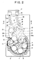
- the coin transporting path 15 has a configuration of approximately circular arc formed about a rotary shaft 14 of the scraper 13. The coin A is then pushed to guide rollers 18 and 19 as illustrated in Fig. 2.
- the coin is not further transported along the coin transporting path 15 in the circumferential direction of the scraper 13.
- the coin A pushed to the guide rollers 18 and 19 is transferred towards a lower end port 16 of a coin carrier duct 17 standing in approximately vertical or upright state. More particularly, the coin A is delivered due to a convex portion of the feeding wing 12 of the scraper 13. The convex portion is formed on the leading side 12a to the rotational direction.
- the coin is fed to the coin carrier duct 17 one by one and is thrown out of an upper outlet port (not shown).
- a guide 21 is disposed to guide a coin along the coin transporting path 15 of approximately circular arc about the rotary shaft 14 by means of feeding wing 12 of the scraper 13.
- any one of adequate guide roller such as a rubber roller, is disposed at the end of the coin transporting path 15 as the guide rollers 18 and 19.
- the guide rollers 18 and 19 serves to interrupt the travel of the coin transferred with being interposed between the feeding wings 12 of the scraper 13 in the circumferential direction of the scraper. As a result, the travel direction of the coin is forced to deviate.
- the well-known coin carrier duct 17 (called in general as an escalator) is uprightly secured at the extended portion of the coin transporting path 15.
- the coin carrier duct 17 comprises a lower end port 16.
- the coin is transferred towards the lower end port 16 of the coin carrier duct 17 by means of the guide rollers 18 and 19 and the convex portion 12a of the feeding wing 12 of the scraper 13.
- guide rollers 19 are disposed with the coin guide 18 in order to guide the coin.
- One of the exemplified guide rollers 18 and 19 are shown in Fig. 3.
- the guide rollers 18 and 19 are formed with taper rollers.
- Each of the taper rollers has a downward taper surface 23.
- a central shaft 25 is passing through a central hole 24 of the taper roller and is also passing through a guide hole 26 penetrating through the base plate 2.
- a slide shoe 27 is attached, thereby the taper roller enables to moving in the transversal direction of the coin transporting path 15.
- the spring force is exerted to draw the slide shoes 27 of a pair of taper rollers with each other by means of a coin spring 28.
- the coin is interposed between the taper rollers 18 and 19 against the spring force.
- the coin is forced to the base plate 2 with the help of the downward taper surfaces 23 to avoid rising up of the coin.
- the guide rollers 18 and 19 having the above mentioned construction make it possible to smoothly feed coins along a curved path required for forcing the travel direction of the coin to the coin carrier vertically standing from the inclined base plate 2. With the construction according to the present invention, it is possible to feed coins even in a vertical coin sorting device with the minimum radius of curvature of the curved path for the coin.
- the present invention it is possible to reduce the width and depth of the coin sorting device with the escalator having the coin carrier duct vertically extending from the device as compared with the conventional one. As a result, it becomes possible to provide, for example, a vertical coin exchanger having remarkably small width and depth.
Landscapes
- Physics & Mathematics (AREA)
- General Physics & Mathematics (AREA)
- Pinball Game Machines (AREA)
- Filling Or Emptying Of Bunkers, Hoppers, And Tanks (AREA)
Abstract
Description
- This invention relates to a coin sorting device for sorting a coin such as a money coin or a token in a coin exchanger, a vending machine or a coin operated gaming machine and, more particularly, this invention relates to a coin sorting device with an escalator. Such a coin sorting device comprises a hopper where a supply of coins are stored in bulk. The coin is delivered one by one from the hopper to a coin receiving hole opened at an upper portion of the device by means of rotation of a rotary disc through an upright coin carrier duct, which in general is called as an escalator.
- Conventionally, such a coin sorting device with an escalator is well known as disclosed in, for example, U.S. Patent No. 4,592,377.
- However, in a conventional well-known coin sorting device with the escalator, an outlet chute projected from one side of the hopper is connected to the lower end of an upright coin carrier duct. Accordingly, it requires some means for supporting the coin carrier duct in an upright state, resulting in a device of an enlarged dimension. The enlarged device disposed in, for example, a vertical coin exchanger has a disadvantage that it makes the coin exchanger wide and deep.
- The present invention is directed to provide a small coin sorting device with an escalator. Thus, a primary object of the present invention is to provide a small coin sorting device with an escalator substantially accompanying with no increase of the width and the depth of a small coin sorting device by means of improving the latter disclosed in, for example, Japanese Examined Patent Publication No. 36040/1988.
- According to the present invention, a coin sorting device comprises a base plate having an upper end portion where a coin carrier duct for delivering a coin in the upward direction is substantially vertically arranged; scraper means for feeding the coin towards said upper end portion, said scraper means comprising a rotational body rotatably supported on said base plate and coin feeding wings radially outwardly extending from said rotational body, each of said coin feeding wings being for use in forcing said coin to said upper end portion by means of rotation of said rotational body; and coin guiding means arranged at said upper end portion for guiding said coin forced to said upper end portion by said coin feeding wings to said coin carrier duct.
- The coin feeding wing may have a convex, being expanded towards rotational direction of said rotational body.
- The coin guiding means may be disposed at said upper end portion and comprise a pair of shaft portions opposing to and being apart from each other at a distance substantially corresponding to a diameter of said coin, and roller portions rotatably disposed to each of said pair of shaft portions, said roller portions being for use in preventing the coin from rising up.
- Each of said roller portions may have a taper surface for forcing said coin against said upper end portion.
- The pair of shaft portions may be disposed at said upper end portion with a distance therebetween being variable.
- A coin sorting device according to the present invention may further comprise a rotary disc opposing to said base plate at a distance corresponding to the thickness of the coin; a guide hole opened on said rotary disc for guiding the coin onto said base plate; and a feeding arm positioned between said base plate and said rotary disc for feeding the coin in said guide hole towards said scraper according to said rotary disc, said scraper receiving the coin transferred from said feeding arm.
- A coin sorting device according to a preferred embodiment of the present invention comprises, as shown in Figs. 1 and 2, a hopper 1 for storing a supply of coins in bulk a hollow
cylindrical case 3 disposed at the lower end of the hopper and secured on aninclined base plate 2, acoin feeding disc 4 disposed on the inclined base plate so as to be rotated in the hollow cylindrical case, anddriving devices coin receiving holes 8 are penetrating through the coin feeding disc, apart from each other along the circumference of the disc. Each of thecoin receiving holes 8 has a dimension for receiving a coin to be fed to the coin feeding disc. Each of coin feeding arms 9 is projected from the back surface of the coin feeding disc at a position between the adjacent coin receiving holes, thereby a coin received in the coin receiving hole is delivered onto the base plate by means of the coin feeding arm accompanying with the rotation of the coin feeding disc. Anoutlet port 10 is formed at a lower end portion of the peripheral surface of the hollow cylindrical case at one side thereof. An outlet guiding member 11 is disposed on the base plate at the downstream of the outlet port for guiding the coin pushed on the base plate to the outlet port. The coin sorting device according to the present invention further comprises ascraper 13 which is rotated in synchronism with thecoin feeding disc 4. Feedingwings 12 of thescraper 13 is positioned beneath thecoin feeding disc 4 and between the adjacent coin receivingholes 8. The coin is delivered due to a convex portion of thefeeding wing 12 of thescraper 13. The convex portion is formed on the leading side to the rotational direction. Acoin carrier duct 17 is uprightly secured at the extended portion of thecoin transporting path 15. Thecoin carrier duct 17 comprises alower end port 16. The coin is transferred towards thelower end port 16 of thecoin carrier duct 17 by means of theguide rollers convex portion 12a of thefeeding wing 12 of thescraper 13. - Other objects and advantageous of the present invention will become apparent from the following description taken together with the drawing in which:
- Fig. 1 is a schematical side view of a coin sorting device with an escalator according to the present invention, where a part of which is illustrated as a cross section;
- Fig. 2 is a schematical plan view of the coin sorting device illustrated in Fig. 1 except for a hopper; and
- Fig. 3 is a cross sectional view taken on the line III-III in Fig. 2.
- Fig. 1 shows an embodiment of the present invention. In Fig. 1, a reference numeral 1 represents a hopper where a supply of coins are stored in bulk. The lower end of the hopper 1 is fastened to the upper end of a hollow
cylindrical case 3. The hollowcylindrical case 3 is removably attached to aninclined base plate 2 in a well-known manner. Theinclined base plate 2 is secured on aplatform 20. - In the hollow
cylindrical case 3, acoin feeding disc 4 is rotatably attached to theinclined base plate 2. A disc boss is secured to arotary shaft 7 driven by adrive motor 5 through atransmission 6. Thus, thecoin feeding disc 4 is rotated in synchronism with therotary shaft 7 in the hollowcylindrical case 3. - In accordance with the above mentioned construction of the present invention, each coin delivered from the hopper 1 to the hollow
cylindrical case 3 is further transferred to one of coin receivingholes 8. As will later be described more detail, thecoin receiving holes 8 are formed on thecoin feeding disc 4 rotated in the hollowcylindrical case 3. The coin received in thecoin receiving hole 8 is transferred onto thebase plate 2 through the hollowcylindrical case 3 by means of a coin feeding arm 9 projected from the back surface of thecoin feeding disc 4. - A plurality of
coin receiving holes 8 are formed on thecoin feeding disc 4 with being apart from each other along the circumference of the disc. Each of thecoin receiving holes 8 has an acceptable size for the coin to be thrown and is penetrating through thecoin feeding disc 4. The coin feeding arm 9 is projected from the back surface of thecoin feeding disc 4 at a position between the adjacentcoin receiving holes coin receiving hole 8. Thus, the coin received in thecoin receiving hole 8 is transferred on thebase plate 2 through the hollowcylindrical case 3 by means of the coin feeding arm 9 accompanying with the rotation of thecoin feeding disc 4. - The coin sorting device according to the present invention further comprises a
scraper 13 which is rotated in synchronism with thecoin feeding disc 4. When the coin feeding arm 9 is rotated, afeeding wing 12 of thescraper 13 is interposed between the back surface of thecoin feeding disc 4 and thebase plate 2 at a position between the adjacentcoin receiving holes 8 by moving from the external position of the hollowcylindrical case 3 through anopening portion 10a formed at the lower portion of the peripheral wall of the hollowcylindrical case 3. In this event, thefeeding wing 12 of thescraper 13 is positioned beneath thecoin feeding disc 4 and between the adjacent coin receivingholes 8. Therefore, thescraper 13 can be smoothly rotated in synchronism with thecoin feeding disc 4 without being interfered by the coin in thecoin receiving hole 8. - Further rotation of the
coin feeding disc 4 makes thefeeding wing 12 of thescraper 13 engage with a tailing edge of the coin A transferred on thebase plate 2 through the coin feeding arm 9. Thus, the coin A is forced onto thebase plate 2 by means of the coin feeding arm 9 and thefeeding wing 12. - An
outlet port 10 is opened on the lower portion of the peripheral surface of the hollowcylindrical case 3 at one side thereof. An outlet guiding member 11 is protruded from thebase plate 2 at the downstream of theoutlet port 10 along the travel direction of thecoin feeding disc 4. The coin transferred onto thebase plate 2 by the coin feeding arm 9 is pushed to the outlet guiding member 11, thereby the travel direction of the coin is forced to deviate towards theoutlet port 10. In other words, the coin A transferred on thebase plate 2 contacts with an outlet guiding member 11 located at the downstream side of anoutlet port 10, thereby the travel direction of the coin A is forced to deviate towards theoutput port 10. - On the
base plate 2, thescraper 13 is disposed beside thecoin feeding disc 4 at the side close to theoutlet port 10 of the hollowcylindrical case 3. The scraper comprisesfeeding wings 12 outwardly radially extending therefrom. Thefeeding wings 12 are equal in number to thecoin receiving holes 8 of thecoin feeding disc 4. Thescraper 13 is disposed such that a tip portion of eachfeeding wing 12 is traveled through the opening 10a being continued from theoutlet port 10 beneath the back surface of thecoin feeding disc 4 in the hollowcylindrical case 3 and projected to a position between the adjacentcoin receiving holes - The
scraper 13 is properly secured to a scraper rotary shaft 14 at the center thereof. The scraper rotary shaft 14 is rotated in synchronism with therotary shaft 7 of thecoin feeding disc 4 by thedrive motor 5 through thetransmission 6. The relative positions of the coin feeding arm 9 and the feedingwing 12 are determined such that, each coin feeding arm 9 of thecoin feeding disc 4 and each feedingwing 12 of thescraper 13 are synchronously rotated at theoutlet port 10 of the hollowcylindrical case 3 in corporation with each other to push the coin towards the outlet guiding member 11. - As described above, the coin A is transferred on the
base plate 2 towards theoutlet port 10 by means of the feedingwing 12 of thescraper 13. Further, the coin is transferred along acoin transporting path 15 by means of the feedingwing 12 of therotating scraper 13. Thecoin transporting path 15 has a configuration of approximately circular arc formed about a rotary shaft 14 of thescraper 13. The coin A is then pushed to guiderollers - Once the coin is pushed to and in contact with the
guide rollers coin transporting path 15 in the circumferential direction of thescraper 13. Thus, the coin A pushed to theguide rollers lower end port 16 of acoin carrier duct 17 standing in approximately vertical or upright state. More particularly, the coin A is delivered due to a convex portion of the feedingwing 12 of thescraper 13. The convex portion is formed on the leadingside 12a to the rotational direction. The coin is fed to thecoin carrier duct 17 one by one and is thrown out of an upper outlet port (not shown). - On the
base plate 2, aguide 21 is disposed to guide a coin along thecoin transporting path 15 of approximately circular arc about the rotary shaft 14 by means of feedingwing 12 of thescraper 13. - As mentioned above, any one of adequate guide roller, such as a rubber roller, is disposed at the end of the
coin transporting path 15 as theguide rollers guide rollers wings 12 of thescraper 13 in the circumferential direction of the scraper. As a result, the travel direction of the coin is forced to deviate. - The well-known coin carrier duct 17 (called in general as an escalator) is uprightly secured at the extended portion of the
coin transporting path 15. Thecoin carrier duct 17 comprises alower end port 16. The coin is transferred towards thelower end port 16 of thecoin carrier duct 17 by means of theguide rollers convex portion 12a of the feedingwing 12 of thescraper 13. - As shown in Fig. 2, guide
rollers 19 are disposed with thecoin guide 18 in order to guide the coin. One of the exemplifiedguide rollers guide rollers downward taper surface 23. Acentral shaft 25 is passing through acentral hole 24 of the taper roller and is also passing through aguide hole 26 penetrating through thebase plate 2. To the end of thecentral shaft 25, aslide shoe 27 is attached, thereby the taper roller enables to moving in the transversal direction of thecoin transporting path 15. The spring force is exerted to draw the slide shoes 27 of a pair of taper rollers with each other by means of acoin spring 28. The coin is interposed between thetaper rollers base plate 2 with the help of the downward taper surfaces 23 to avoid rising up of the coin. - The
guide rollers inclined base plate 2. With the construction according to the present invention, it is possible to feed coins even in a vertical coin sorting device with the minimum radius of curvature of the curved path for the coin. - Further, according to the present invention, it is possible to reduce the width and depth of the coin sorting device with the escalator having the coin carrier duct vertically extending from the device as compared with the conventional one. As a result, it becomes possible to provide, for example, a vertical coin exchanger having remarkably small width and depth.
- While particular embodiments of the present invention have been illustrated and described above, it will be readily understood by those skilled in the art that the present invention can be varied and modified without departing from the scope and spirit of the appended claims.
Claims (6)
- A coin sorting device comprising:
a base plate having an upper end portion where a coin carrier duct for delivering a coin in the upward direction is substantially vertically arranged;
scraper means for feeding the coin towards said upper end portion, said scraper means comprising a rotational body rotatably supported on said base plate and coin feeding wings radially outwardly extending from said rotational body, each of said coin feeding wings being for use in forcing said coin to said upper end portion by means of rotation of said rotational body; and
coin guiding means arranged at said upper end portion for guiding said coin forced to said upper end portion by said coin feeding wings to said coin carrier duct. - A coin sorting device as claimed in Claim 1, wherein said coin feeding wing has a convex being expanded towards rotational direction of said rotational body.
- A coin sorting device as claimed in Claim 1, wherein said coin guiding means is disposed at said upper end portion and comprises a pair of shaft portions opposing to and being apart from each other at a distance substantially corresponding to a diameter of said coin, and roller portions rotatably disposed to each of said pair of shaft portions, said roller portions are for use in preventing the coin from rising up.
- A coin sorting device as claimed in Claim 3, wherein each of said roller portions has a taper surface for forcing said coin against said upper end portion.
- A coin sorting device as claimed in Claim 1, said pair of shaft portions are disposed at said upper end portion with a distance therebetween being variable.
- A coin sorting device as claimed in Claim 1 further comprising:
a rotary disc opposing to said base plate at a distance corresponding to the thickness of the coin;
a guide hole opened on said rotary disc for guiding the coin onto said base plate; and
a feeding arm positioned between said base plate and said rotary disc for feeding the coin in said guide hole towards said scraper according to said rotary disc,
said scraper receives the coin transferred from said feeding arm.
Priority Applications (3)
| Application Number | Priority Date | Filing Date | Title |
|---|---|---|---|
| EP92309828A EP0594902B1 (en) | 1992-10-27 | 1992-10-27 | Coin feeding device with an escalator |
| ES92309828T ES2102468T3 (en) | 1992-10-27 | 1992-10-27 | COIN FEED DEVICE WITH A CLIMBER. |
| US07/970,680 US5282769A (en) | 1992-10-27 | 1992-11-04 | Coin sorting device with an escalator |
Applications Claiming Priority (2)
| Application Number | Priority Date | Filing Date | Title |
|---|---|---|---|
| EP92309828A EP0594902B1 (en) | 1992-10-27 | 1992-10-27 | Coin feeding device with an escalator |
| US07/970,680 US5282769A (en) | 1992-10-27 | 1992-11-04 | Coin sorting device with an escalator |
Publications (2)
| Publication Number | Publication Date |
|---|---|
| EP0594902A1 true EP0594902A1 (en) | 1994-05-04 |
| EP0594902B1 EP0594902B1 (en) | 1997-06-04 |
Family
ID=26132249
Family Applications (1)
| Application Number | Title | Priority Date | Filing Date |
|---|---|---|---|
| EP92309828A Expired - Lifetime EP0594902B1 (en) | 1992-10-27 | 1992-10-27 | Coin feeding device with an escalator |
Country Status (3)
| Country | Link |
|---|---|
| US (1) | US5282769A (en) |
| EP (1) | EP0594902B1 (en) |
| ES (1) | ES2102468T3 (en) |
Cited By (1)
| Publication number | Priority date | Publication date | Assignee | Title |
|---|---|---|---|---|
| NL1024052C2 (en) * | 2002-08-27 | 2005-08-09 | Asahi Seiko Co Ltd | Device for dispensing coins or similar objects stored therein. |
Families Citing this family (10)
| Publication number | Priority date | Publication date | Assignee | Title |
|---|---|---|---|---|
| JP2573634Y2 (en) * | 1993-02-05 | 1998-06-04 | 旭精工株式会社 | Coin delivery device |
| JP3206699B2 (en) * | 1994-06-27 | 2001-09-10 | 旭精工株式会社 | Coin delivery device |
| GB2335775B (en) * | 1998-03-27 | 2002-01-30 | Mars Inc | Coin dispensing |
| KR100600420B1 (en) * | 1999-08-06 | 2006-07-13 | 아사히 세이코 가부시키가이샤 | Coin Hopper Equipment |
| JP4784805B2 (en) * | 2004-03-31 | 2011-10-05 | 旭精工株式会社 | Coin hopper rotating disk |
| US8522950B2 (en) | 2011-09-09 | 2013-09-03 | Outerwall Inc. | Debris diverter for coin counting machine and associated method of manufacture and operation |
| US9036890B2 (en) | 2012-06-05 | 2015-05-19 | Outerwall Inc. | Optical coin discrimination systems and methods for use with consumer-operated kiosks and the like |
| US8967361B2 (en) | 2013-02-27 | 2015-03-03 | Outerwall Inc. | Coin counting and sorting machines |
| US9022841B2 (en) | 2013-05-08 | 2015-05-05 | Outerwall Inc. | Coin counting and/or sorting machines and associated systems and methods |
| US9235945B2 (en) | 2014-02-10 | 2016-01-12 | Outerwall Inc. | Coin input apparatuses and associated methods and systems |
Citations (5)
| Publication number | Priority date | Publication date | Assignee | Title |
|---|---|---|---|---|
| EP0204405A2 (en) * | 1985-06-07 | 1986-12-10 | Asahi Seiko Kabushiki Kaisha | Coin dispensing apparatus |
| WO1990002389A1 (en) * | 1988-08-18 | 1990-03-08 | Popham, Charles, F. | Coin storage and dispensing apparatus |
| US4978322A (en) * | 1989-02-13 | 1990-12-18 | International Game Technology | Coin wiper for escalator hopper |
| EP0469886A2 (en) * | 1990-08-02 | 1992-02-05 | Asahi Seiko Kabushiki Kaisha | Coin conveyor for successively transporting coins |
| GB2251114A (en) * | 1990-11-15 | 1992-06-24 | Asahi Seiko Co Ltd | Outlet device for coin payout hoppers |
Family Cites Families (7)
| Publication number | Priority date | Publication date | Assignee | Title |
|---|---|---|---|---|
| GB1419609A (en) * | 1974-03-08 | 1975-12-31 | Seeburg Corp | Dispensing device for disc-shaped members |
| US4592377A (en) * | 1984-07-02 | 1986-06-03 | Igt | Coin escalator |
| AU5171885A (en) * | 1986-01-25 | 1987-07-02 | Uzihara, H. | Coin delivery |
| JPS63314868A (en) * | 1987-10-03 | 1988-12-22 | Nec Corp | Manufacture of mos semiconductor device |
| JPH01304595A (en) * | 1988-06-01 | 1989-12-08 | Matsushita Hiromi | Hopper type coin discharging device |
| US5046989A (en) * | 1988-08-18 | 1991-09-10 | Jack Dass | Coin storage and dispensing apparatus |
| US5170874A (en) * | 1990-08-02 | 1992-12-15 | Asahi Seiko Kabushiki Kaisha | Coin conveyor for successively transporting coins |
-
1992
- 1992-10-27 ES ES92309828T patent/ES2102468T3/en not_active Expired - Lifetime
- 1992-10-27 EP EP92309828A patent/EP0594902B1/en not_active Expired - Lifetime
- 1992-11-04 US US07/970,680 patent/US5282769A/en not_active Expired - Lifetime
Patent Citations (5)
| Publication number | Priority date | Publication date | Assignee | Title |
|---|---|---|---|---|
| EP0204405A2 (en) * | 1985-06-07 | 1986-12-10 | Asahi Seiko Kabushiki Kaisha | Coin dispensing apparatus |
| WO1990002389A1 (en) * | 1988-08-18 | 1990-03-08 | Popham, Charles, F. | Coin storage and dispensing apparatus |
| US4978322A (en) * | 1989-02-13 | 1990-12-18 | International Game Technology | Coin wiper for escalator hopper |
| EP0469886A2 (en) * | 1990-08-02 | 1992-02-05 | Asahi Seiko Kabushiki Kaisha | Coin conveyor for successively transporting coins |
| GB2251114A (en) * | 1990-11-15 | 1992-06-24 | Asahi Seiko Co Ltd | Outlet device for coin payout hoppers |
Cited By (1)
| Publication number | Priority date | Publication date | Assignee | Title |
|---|---|---|---|---|
| NL1024052C2 (en) * | 2002-08-27 | 2005-08-09 | Asahi Seiko Co Ltd | Device for dispensing coins or similar objects stored therein. |
Also Published As
| Publication number | Publication date |
|---|---|
| EP0594902B1 (en) | 1997-06-04 |
| ES2102468T3 (en) | 1997-08-01 |
| US5282769A (en) | 1994-02-01 |
Similar Documents
| Publication | Publication Date | Title |
|---|---|---|
| EP0461889B1 (en) | Coin dispensing apparatus | |
| US4474197A (en) | Coin transfer apparatus | |
| KR900000225B1 (en) | Coin dispensing apparatus | |
| EP0594902A1 (en) | Coin sorting device with an escalator | |
| EP0526049B1 (en) | Coin feeding device | |
| US3948280A (en) | Coin lifting device having a flexible rotor disc | |
| US5000718A (en) | Coin dispensing apparatus | |
| KR910008804B1 (en) | Coin dispensing machine | |
| US5181881A (en) | Outlet device for coin payout hoppers | |
| JP3206699B2 (en) | Coin delivery device | |
| MXPA97007462A (en) | Large-volume-shaped apparatus for ejecting disk bodies. | |
| KR960001446B1 (en) | Coin delivery device with escalator | |
| AU657170B2 (en) | Coin sorting device with an escalator | |
| JP2782570B2 (en) | Coin sending device | |
| EP0442696B1 (en) | Coin dispensing apparatus | |
| EP0211307A2 (en) | Paper discharging device | |
| JPH0844929A (en) | Coin lifting device | |
| JP2504840Y2 (en) | Coin transfer device of coin processing machine | |
| JP3738067B2 (en) | Coin separator | |
| JP2699239B2 (en) | Coin delivery device | |
| JPH0110682Y2 (en) | ||
| JPH0110688Y2 (en) | ||
| JP2529122Y2 (en) | Coin ejection device | |
| JPS5892083A (en) | Coin feeder for coin selector | |
| JP2990571B2 (en) | Coin delivery device with pick-up function |
Legal Events
| Date | Code | Title | Description |
|---|---|---|---|
| PUAI | Public reference made under article 153(3) epc to a published international application that has entered the european phase |
Free format text: ORIGINAL CODE: 0009012 |
|
| AK | Designated contracting states |
Kind code of ref document: A1 Designated state(s): CH ES FR GB LI |
|
| 17P | Request for examination filed |
Effective date: 19940929 |
|
| 17Q | First examination report despatched |
Effective date: 19950710 |
|
| GRAG | Despatch of communication of intention to grant |
Free format text: ORIGINAL CODE: EPIDOS AGRA |
|
| GRAH | Despatch of communication of intention to grant a patent |
Free format text: ORIGINAL CODE: EPIDOS IGRA |
|
| GRAH | Despatch of communication of intention to grant a patent |
Free format text: ORIGINAL CODE: EPIDOS IGRA |
|
| GRAA | (expected) grant |
Free format text: ORIGINAL CODE: 0009210 |
|
| AK | Designated contracting states |
Kind code of ref document: B1 Designated state(s): CH ES FR GB LI |
|
| REG | Reference to a national code |
Ref country code: CH Ref legal event code: NV Representative=s name: E. BLUM & CO. PATENTANWAELTE Ref country code: CH Ref legal event code: EP |
|
| ET | Fr: translation filed | ||
| REG | Reference to a national code |
Ref country code: ES Ref legal event code: FG2A Ref document number: 2102468 Country of ref document: ES Kind code of ref document: T3 |
|
| PLBE | No opposition filed within time limit |
Free format text: ORIGINAL CODE: 0009261 |
|
| 26N | No opposition filed | ||
| REG | Reference to a national code |
Ref country code: GB Ref legal event code: IF02 |
|
| REG | Reference to a national code |
Ref country code: CH Ref legal event code: PFA Owner name: ASAHI SEIKO KABUSHIKI KAISHA Free format text: ASAHI SEIKO KABUSHIKI KAISHA#NO. 24-15, MINAMIAOYAMA 2-CHOME#MINATO-KU, TOKYO 107 (JP) -TRANSFER TO- ASAHI SEIKO KABUSHIKI KAISHA#NO. 24-15, MINAMIAOYAMA 2-CHOME#MINATO-KU, TOKYO 107 (JP) |
|
| PGFP | Annual fee paid to national office [announced via postgrant information from national office to epo] |
Ref country code: CH Payment date: 20081031 Year of fee payment: 17 |
|
| REG | Reference to a national code |
Ref country code: CH Ref legal event code: PL |
|
| PG25 | Lapsed in a contracting state [announced via postgrant information from national office to epo] |
Ref country code: LI Free format text: LAPSE BECAUSE OF NON-PAYMENT OF DUE FEES Effective date: 20091031 Ref country code: CH Free format text: LAPSE BECAUSE OF NON-PAYMENT OF DUE FEES Effective date: 20091031 |
|
| PGFP | Annual fee paid to national office [announced via postgrant information from national office to epo] |
Ref country code: FR Payment date: 20101104 Year of fee payment: 19 |
|
| PGFP | Annual fee paid to national office [announced via postgrant information from national office to epo] |
Ref country code: GB Payment date: 20101021 Year of fee payment: 19 |
|
| PGFP | Annual fee paid to national office [announced via postgrant information from national office to epo] |
Ref country code: ES Payment date: 20101021 Year of fee payment: 19 |
|
| GBPC | Gb: european patent ceased through non-payment of renewal fee |
Effective date: 20111027 |
|
| REG | Reference to a national code |
Ref country code: FR Ref legal event code: ST Effective date: 20120629 |
|
| PG25 | Lapsed in a contracting state [announced via postgrant information from national office to epo] |
Ref country code: FR Free format text: LAPSE BECAUSE OF NON-PAYMENT OF DUE FEES Effective date: 20111102 Ref country code: GB Free format text: LAPSE BECAUSE OF NON-PAYMENT OF DUE FEES Effective date: 20111027 |
|
| REG | Reference to a national code |
Ref country code: ES Ref legal event code: FD2A Effective date: 20130417 |
|
| PG25 | Lapsed in a contracting state [announced via postgrant information from national office to epo] |
Ref country code: ES Free format text: LAPSE BECAUSE OF NON-PAYMENT OF DUE FEES Effective date: 20111028 |