EP0594850A1 - Method for producing roll of core-less toilet paper and roll of core-less toilet paper produced by the same method - Google Patents
Method for producing roll of core-less toilet paper and roll of core-less toilet paper produced by the same method Download PDFInfo
- Publication number
- EP0594850A1 EP0594850A1 EP92908208A EP92908208A EP0594850A1 EP 0594850 A1 EP0594850 A1 EP 0594850A1 EP 92908208 A EP92908208 A EP 92908208A EP 92908208 A EP92908208 A EP 92908208A EP 0594850 A1 EP0594850 A1 EP 0594850A1
- Authority
- EP
- European Patent Office
- Prior art keywords
- toilet paper
- paper
- winding
- roll
- toilet
- Prior art date
- Legal status (The legal status is an assumption and is not a legal conclusion. Google has not performed a legal analysis and makes no representation as to the accuracy of the status listed.)
- Withdrawn
Links
Images


Classifications
-
- B—PERFORMING OPERATIONS; TRANSPORTING
- B65—CONVEYING; PACKING; STORING; HANDLING THIN OR FILAMENTARY MATERIAL
- B65H—HANDLING THIN OR FILAMENTARY MATERIAL, e.g. SHEETS, WEBS, CABLES
- B65H23/00—Registering, tensioning, smoothing or guiding webs
- B65H23/04—Registering, tensioning, smoothing or guiding webs longitudinally
- B65H23/18—Registering, tensioning, smoothing or guiding webs longitudinally by controlling or regulating the web-advancing mechanism, e.g. mechanism acting on the running web
- B65H23/195—Registering, tensioning, smoothing or guiding webs longitudinally by controlling or regulating the web-advancing mechanism, e.g. mechanism acting on the running web in winding mechanisms or in connection with winding operations
- B65H23/1955—Registering, tensioning, smoothing or guiding webs longitudinally by controlling or regulating the web-advancing mechanism, e.g. mechanism acting on the running web in winding mechanisms or in connection with winding operations and controlling web tension
-
- A—HUMAN NECESSITIES
- A47—FURNITURE; DOMESTIC ARTICLES OR APPLIANCES; COFFEE MILLS; SPICE MILLS; SUCTION CLEANERS IN GENERAL
- A47K—SANITARY EQUIPMENT NOT OTHERWISE PROVIDED FOR; TOILET ACCESSORIES
- A47K10/00—Body-drying implements; Toilet paper; Holders therefor
- A47K10/16—Paper towels; Toilet paper; Holders therefor
-
- B—PERFORMING OPERATIONS; TRANSPORTING
- B65—CONVEYING; PACKING; STORING; HANDLING THIN OR FILAMENTARY MATERIAL
- B65H—HANDLING THIN OR FILAMENTARY MATERIAL, e.g. SHEETS, WEBS, CABLES
- B65H18/00—Winding webs
-
- B—PERFORMING OPERATIONS; TRANSPORTING
- B65—CONVEYING; PACKING; STORING; HANDLING THIN OR FILAMENTARY MATERIAL
- B65H—HANDLING THIN OR FILAMENTARY MATERIAL, e.g. SHEETS, WEBS, CABLES
- B65H18/00—Winding webs
- B65H18/08—Web-winding mechanisms
- B65H18/26—Mechanisms for controlling contact pressure on winding-web package, e.g. for regulating the quantity of air between web layers
-
- B—PERFORMING OPERATIONS; TRANSPORTING
- B65—CONVEYING; PACKING; STORING; HANDLING THIN OR FILAMENTARY MATERIAL
- B65H—HANDLING THIN OR FILAMENTARY MATERIAL, e.g. SHEETS, WEBS, CABLES
- B65H18/00—Winding webs
- B65H18/28—Wound package of webs
-
- B—PERFORMING OPERATIONS; TRANSPORTING
- B65—CONVEYING; PACKING; STORING; HANDLING THIN OR FILAMENTARY MATERIAL
- B65H—HANDLING THIN OR FILAMENTARY MATERIAL, e.g. SHEETS, WEBS, CABLES
- B65H19/00—Changing the web roll
- B65H19/22—Changing the web roll in winding mechanisms or in connection with winding operations
- B65H19/28—Attaching the leading end of the web to the replacement web-roll core or spindle
-
- B—PERFORMING OPERATIONS; TRANSPORTING
- B65—CONVEYING; PACKING; STORING; HANDLING THIN OR FILAMENTARY MATERIAL
- B65H—HANDLING THIN OR FILAMENTARY MATERIAL, e.g. SHEETS, WEBS, CABLES
- B65H75/00—Storing webs, tapes, or filamentary material, e.g. on reels
- B65H75/02—Cores, formers, supports, or holders for coiled, wound, or folded material, e.g. reels, spindles, bobbins, cop tubes, cans, mandrels or chucks
- B65H75/18—Constructional details
- B65H75/24—Constructional details adjustable in configuration, e.g. expansible
- B65H75/242—Expansible spindles, mandrels or chucks, e.g. for securing or releasing cores, holders or packages
- B65H75/243—Expansible spindles, mandrels or chucks, e.g. for securing or releasing cores, holders or packages actuated by use of a fluid
- B65H75/2437—Expansible spindles, mandrels or chucks, e.g. for securing or releasing cores, holders or packages actuated by use of a fluid comprising a fluid-pressure-actuated elastic member, e.g. a diaphragm or a pneumatic tube
-
- B—PERFORMING OPERATIONS; TRANSPORTING
- B65—CONVEYING; PACKING; STORING; HANDLING THIN OR FILAMENTARY MATERIAL
- B65H—HANDLING THIN OR FILAMENTARY MATERIAL, e.g. SHEETS, WEBS, CABLES
- B65H2404/00—Parts for transporting or guiding the handled material
- B65H2404/40—Shafts, cylinders, drums, spindles
- B65H2404/43—Rider roll construction
-
- B—PERFORMING OPERATIONS; TRANSPORTING
- B65—CONVEYING; PACKING; STORING; HANDLING THIN OR FILAMENTARY MATERIAL
- B65H—HANDLING THIN OR FILAMENTARY MATERIAL, e.g. SHEETS, WEBS, CABLES
- B65H2406/00—Means using fluid
- B65H2406/30—Suction means
- B65H2406/36—Means for producing, distributing or controlling suction
- B65H2406/365—Means for producing, distributing or controlling suction selectively blowing or sucking
-
- B—PERFORMING OPERATIONS; TRANSPORTING
- B65—CONVEYING; PACKING; STORING; HANDLING THIN OR FILAMENTARY MATERIAL
- B65H—HANDLING THIN OR FILAMENTARY MATERIAL, e.g. SHEETS, WEBS, CABLES
- B65H2408/00—Specific machines
- B65H2408/20—Specific machines for handling web(s)
- B65H2408/23—Winding machines
- B65H2408/235—Cradles
-
- B—PERFORMING OPERATIONS; TRANSPORTING
- B65—CONVEYING; PACKING; STORING; HANDLING THIN OR FILAMENTARY MATERIAL
- B65H—HANDLING THIN OR FILAMENTARY MATERIAL, e.g. SHEETS, WEBS, CABLES
- B65H2515/00—Physical entities not provided for in groups B65H2511/00 or B65H2513/00
- B65H2515/12—Density
-
- B—PERFORMING OPERATIONS; TRANSPORTING
- B65—CONVEYING; PACKING; STORING; HANDLING THIN OR FILAMENTARY MATERIAL
- B65H—HANDLING THIN OR FILAMENTARY MATERIAL, e.g. SHEETS, WEBS, CABLES
- B65H2701/00—Handled material; Storage means
- B65H2701/10—Handled articles or webs
- B65H2701/18—Form of handled article or web
- B65H2701/184—Wound packages
- B65H2701/1846—Parts concerned
-
- Y—GENERAL TAGGING OF NEW TECHNOLOGICAL DEVELOPMENTS; GENERAL TAGGING OF CROSS-SECTIONAL TECHNOLOGIES SPANNING OVER SEVERAL SECTIONS OF THE IPC; TECHNICAL SUBJECTS COVERED BY FORMER USPC CROSS-REFERENCE ART COLLECTIONS [XRACs] AND DIGESTS
- Y10—TECHNICAL SUBJECTS COVERED BY FORMER USPC
- Y10S—TECHNICAL SUBJECTS COVERED BY FORMER USPC CROSS-REFERENCE ART COLLECTIONS [XRACs] AND DIGESTS
- Y10S242/00—Winding, tensioning, or guiding
- Y10S242/03—Coreless coilers
Definitions
- the present invention relates to a method of producing a coreless toilet paper roll and to a coreless toilet paper produced thereby.
- the most popularly used toilet paper holder at present is such type that has a pair of side brackets for mounting a detachable supporting bar.
- the detachable supporting bar is, in general case, a formed plastic hollow pipe having a diameter of about 20 to 35 mm generally.
- the most popularly used toilet paper roll is such type that has a rolled paper tissue T and a paper pipe or core C inserted into the tissue T, as shown in Fig.15.
- the paper pipe C has an inner diameter of about 35 to 40 mm so as to be attached to the above mentioned holder by using the detachable supporting bar.
- coreless toilet paper roll which is made by winding a paper with remaining merely a small center hole for receiving a thin rigid rod to be attached to a holder, for example, the rigid rod having a diameter of 5 to 10 mm or so.
- the present invention is not directed to such type of coreless toilet paper having merely small hole in the roll center.
- the coreless toilet paper roll to which the present invention is directed means the above mentioned most popular type of toilet papers having a center hole capable of receiving the thick detachable supporting bar therein.
- the "core" of "the coreless toilet paper” means the above-mentioned paper pipe C ( see Fig.15 ) which has an inner diameter of about 35 to 40 mm, and which is inserted in the center of roll.
- a used toilet paper is changed for new toilet paper roll for example, every morning. And it requires many hand to remove the paper pipe C of the toilet paper roll from the holders, and to dispose them as dust. Further, the usage of many paper pipe requires material cost, and requires also many hands for setting a paper pipe on a winding shaft, both of which increase production cost.
- the inventors pay attention to the self-loose problem of the toilet paper roll as a basic object to be solved.
- the inventors have energetically researched the cause why the toilet paper cannot be tightly wound, and have found the following facts at last.
- water or water-solution of adhesive agent is sprayed to the paper on the winding shaft in order to temporally fix the paper with the winding shaft or to temporally fix several paper layers with each other.
- the paper absorbing water is elongated in the longitudinal and lateral directions.
- the elongation in the longitudinal direction is about 10 % to the original length. Therefore, when the paper feeding speed and the winding speed are the same, the toilet paper lacks tension in the winding part. Therefore, the toilet paper roll T tends to be loose at the inside portion after the winding.
- both winding part and paper feeding-and-processing part are gradually decelerated and come to halt at end.
- the toilet paper might be fed at a speed faster than a mechanical part of the winder due to the inertia of the toilet paper itself. Therefore, the outside portion of the toilet paper roll also lacks tension for winding and tends to be loose.
- a toilet paper cannot be produced without winding around a paper pipe C as a core, since the toilet paper has characteristics of low density, high flexibility due to crape treatment or the like, and very low strength in comparison with a paper for news paper and a material paper for corrugated cardboard.
- the present invention provides a coreless toilet paper which does not become loose, which has no inside projection, and which can be used to the last.
- a method of producing a coreless toilet paper roll by preparing a toilet paper winder comprising a paper feeding-and-processing part for rewinding a toilet paper from a wound roll made by a paper making machine, processing the paper, as occasion demands, and feeding the paper to a winding part, and the winding part for winding the toilet paper on a winding shaft in a roll shape so as to produce a coreless toilet paper,
- the winding shaft having a winding tubular member with several rows of lugs capable of radially projecting/drawing-back therefrom, plural leaves each having an arc-shaped cross section, extending in an axial direction and being fixed to the lugs of each row, and an elastic outer tube having good slideability and covering the leaves, and at the toilet paper winding process, by winding the toilet paper such that the winding speed in the winding part is faster than the paper feeding speed in the paper feeding-and-processing part at beginning period and final period of the toilet paper winding step, by leaving the
- the toilet paper even if the toilet paper elongates due to spray of water or water solvent of adhesive agent of winding beginning, the elongation can be absorbed since the winding speed of the winding part is faster than the paper feeding speed in the paper feeding-and-processing part at the beginning of winding. Therefore, the toilet paper can be wound around the winding shaft with suitable tension at the beginning period. Further, though the toilet paper is fed with a speed faster than the decelerating mechanism part due to dynamic inertia at the final period of winding, the over running can be absorbed since the winding speed in the winding part is faster than the paper feeding-and-processing part. Therefore, the toilet paper also can be wound with suitable tension at the final period. Further, since the leaves are left projecting for predetermined time after the winding step is completed, the toilet paper receives pressure and the configuration of the roll is fixed as it is. Therefore, the configuration of the roll will not be loose for long time.
- the winding shaft of the present invention has wide contacting surfaces, since the leaves divides radially the outer surface of the winding shaft into several sectors. Therefore, though the toilet paper is directly wound around the winding shaft without using paper pipe, the inner surface of the wound toilet paper can be supported with low face-contact-pressure with the wide contacting surface. Therefore, though the suitable tension is applied during winding operation and is left under compressed condition for the predetermined time, the toilet paper do not be damaged. Further, since the leaves are wrapped with an elastic and slideable outer tube, the paper is not pinched with the leaves, and therefore any projection do not made in the center hollow of the roll.
- a toilet paper roll having a roll body made of a rolled material paper for toilet paper, wherein beginning layer is wound tightly, and turns of paper are gradually softened from the middle layer to the outermost layer, a hole for receiving a supporting bar of a toilet paper holder is formed in a center of the roll, and further, the inner surface of the hole is smooth without projection .
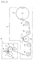
- Fig.12 shows a typical toilet paper winder used now.
- the mechanism part of the winder can be generally divided into a paper feeding-and-processing part A and a winding part B.
- the paper feeding-and-processing part A means a part for rewinding a toilet paper P from a wound roll R which is a roll of 1,000 to 1,500 mm in diameter of a toilet paper P made by a paper making machine, for processing the paper as occasion demands, and for feeding the paper to the winding part.
- the process of paper applied in the paper feeding-and-processing part A includes various kinds of process, such as an embossing process, a notching process, a crape treatment, and the like.
- Such processing mechanisms are suitably assembled in the paper feeding-and-processing part A as occasion demands.
- a notching mechanism having a roller 20 and a cutter 21.
- Numeral 22 shows a guide roller.
- the winding part B means a part for winding a toilet paper P on a winding shaft 1 in order to produce a coreless toilet paper roll.
- the winding part B has driving rollers 2,3, a riding roller 4, a nip roller 5, and the like, as main functional elements.
- the winding part B by rotating the driving rollers 2, 3, a fed toilet paper P is wound on the winding shaft 1, and the toilet paper roll T is urged against the winding shaft 1 by the riding roller 4.
- Fig.2 shows a beginning state of winding of toilet paper P in the winding part B.
- Wound roll R after paper making is 1,000 to 2,000 mm in width and is fed to the winding part B with the original width remained.
- the wide paper is cut with a cutter 6 into 114 mm width as determined in JIS standard.
- Numeral 7 shows a receiving stand for receiving a toilet paper roll to after the winding is completed
- numeral 8 shows a knife for cutting the tail end of the fully wound toilet paper roll in the direction of width. After the toilet paper roll To of which winding has been previously completed is put on the receiving stand 7, the paper P is cut with the knife 8, and the portion shown by a broken line of the paper P is wound on a winding roll 1 as shown by a real line.
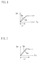
- Fig.5 The changes of the winding speed Sa and the paper feeding speed Sb in one winding cycle mentioned above are shown in Fig.5.
- Sp means a winding speed
- Tm means the winding time.
- the winding speed Sb in the winding part B is faster than the paper feeding speed Sa in the paper feeding-and-processing part A for the beginning period d1 and the final period d3, and the former is the same as the latter in the middle period d2.
- the toilet paper can be tightly wound at the beginning period d1.
- the tension of winding gradually decreases. Therefore, the paper is wound soft.
- the tension decreases and is also wound soft, since dynamic inertia of the paper P operates in the direction of paper feeding, during the winding.
- the obtained toilet paper roll has a tightly wound portion for the beginning period d1 and a gradually softened winding portion from the middle winding layer to the outermost layer.
- a toilet paper roll T having good wound shape which is not easily loosened. Beside, since the water sprayed at the beginning period will escape before the finish of winding, the paper of the beginning period can be easily peeled off without sticking with each other. Accordingly, the toilet paper can be used to the last.
- the above mentioned speed difference Sd1, Sd2 between the winding speed Sb and the paper feeding speed Sa can be calculated from a ratio of elongation of the paper due to water spray, a ratio of deceleration due to dynamic inertia, a speed difference required for suitable tension, and the like.
- the speed difference is about 10 %, the difference of course can be lower or higher than 10 % in accordance with construction or performance of the winder, quality of the paper, and the like.
- the beginning winding period where the winding speed Sa is faster than the paper feeding speed Sb accords to the acceleration range in the embodiment shown in Fig.5, the former can be a part of the acceleration range as is in Fig.6.
- the beginning period can also enter to a part of the constant speed range with passing beyond the acceleration range as shown in Fig.7.
- the final winding period can be a part of the deceleration range of the whole winder, and can also enter to the part of constant speed range.
- a fine control of speed for making the winding tension suitable can be performed.
- the driving roll 2 rotates about 0.2 % upper than paper feeding speed in the paper feeding-and-processing part A
- the driving roll 3 rotates about 0.3 % upper, and for the riding roll 4 about 0.4 % upper.
- the speed ratio becomes to the mentioned as following table. Table Beginning period Middle period Final period Driving roll 2 1.12 1.02 1.12 Driving roll 3 1.13 1.03 1.13 Roll 4 1.14 1.04 1.14 Paper feeding-and-processing part 1.00 1.00 1.00 1.00
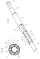
- Fig.8 is a partially broken perspective view of a winding shaft 1 of an embodiment according to the present invention
- Fig.9 is an enlarged sectional view of the winding shaft 1.
- 1a denotes a tubular member of the winding shaft.
- the tubular member 1a is a metal pipe with rigidity necessary as a winding shaft.
- the tubular member 1a has, at both ends, bearing portions 16 for supporting the winding shaft 1 during winding operation.
- An elastomeric tube 17 made of rubber or polyurethane is inserted into the tubular member 1a, and air can be fed in and exhausted from the elastomeric tube 17 through an air vent 15 provided at an end of the winding shaft 1. Beside, the elastomeric tube 17 is closed at another end to which the air vent 15 is not connected, and therefore, the elastomeric tube 17 is inflated radially as air is supplied, and is deflated as air is exhausted.
- the above mentioned tubular member 1a has elongated holes 14 with distance of 120 degrees, and the several set of holes 14 are arranged with suitable distance in the axial direction. Further, a lug 12 is inserted in each elongated hole 14 such that the lug 12 can go out and in through the hole 14.
- a leg member 18 having an arc-shaped cross section and extending in the axial direction is fixed to the lower end of the lug 12, and the leg member 18 is situated between the inside surface of the tubular member 1a and the out side surface of the elastomeric tube 17.
- “row” means a group of elongated holes 14 or lugs 12 existing on the same line extending in the axial direction. In the illustrated embodiment has three rows, and each row has ten elongated holes 14 and lugs 12.
- each lug 12 has a leaf 10 fixed thereon.
- the leaf 10 is made of duralumin.
- the leaf 10 might be formed with the lug 12 as one body, and an individual leaf might be fixed to the lug 12, for example, by fastening with bolts or screws.
- the leaf 10 has an arc-shaped cross section and extends in the axial direction. Therefore, by fixing the leaf on all of rows of the lugs 12, the out side surface of the tubular member 1 is almost covered with the leaves 10, with remaining a little gap between leaves 10 neighboring each other. Of course, the out line determined by the three rows of leaves 10 should be a circle.
- the lugs 12 and leaves 10 are arranged as three rows in the above mentioned embodiment, four or more rows can be employed. Further, the number of holes in a row might be larger or smaller than ten. Further, a common elongated leaf 10 can be fixed for each raw, and the leaf 10 can be divided into two or more pieces in the axial direction if the winding shaft is long.
- the leaf 10 is covered with an outer tube 11 so as to be wrapped.
- the outer tube 11 is suitably elastomeric and has good slideability.
- an polyurethane resin tube might be suitably employed.
- the leaves 10 are expanded radially as shown in Fig.10, when air is supplied in the elastomeric tube 17 through the air vent 15, and the leaves 10 are closed radially as shown in Fig.11, when air is exhausted.
- the toilet paper T When a toilet paper roll T is wound on the winding shaft 1 of the embodiment with above mentioned construction, the toilet paper T is wound in such state that the three leaves 10 are expanded radially as shown in Fig.10. In this case, an outer tube 11 exist on the outer surface of the three leaves 10 which have an almost correct circle profile, and the gaps d between adjacent leaves 10 are closed. Further, since the inner surface of the toilet paper role is wholly in contact with the outer surface of the outer tube 11, the toilet paper roll T can be wound without paper pipe. When the winding shaft 1 is used, any axial projection do not made on the inner surface of the hollow h of the toilet paper roll T, since the paper is not pushed and cramped in the gaps d .
- the leaves 10 are still held to be expanded radially for a determined period, for example, 10 to 20 minutes.
- the toilet paper is subjected to a pressure, and therefore, the toilet paper roll fixes the self shape and can hold the shape long time.
- Fig.1 shows a coreless toilet paper roll T according to the present invention, which is obtained through the above mentioned method.
- no paper pipe is used in the coreless toilet paper roll T, and the roll body is made by merely winding a raw paper b for toilet paper use.
- a hole h capable of inserting a supporting bar of a toilet paper holder is formed in the center of the roll body.
- the toilet paper T can be used by setting to the most popular toilet paper holder, by inserting a detachable supporting bar through the center hole h . And when all paper is spent, the toilet paper can be changed by merely setting a new toilet paper roll T to the supporting bar as it is, since any paper pipe is not left on the supporting bar. Therefore, there is no trouble for taking out, collecting and disposing the paper pipe as required in the conventional one. Further, the whole paper can be used to the last, since the paper is merely wound without using adhesive agent. Further, when the toilet paper roll is used, the roll do not raise any uncomfortable noise which might generates shyness.
- any known material for the toilet paper can be used for the material of the toilet paper roll of the present invention. Therefore, various material papers made of crashed wood pulp, bleached chemical pulp, old paper pulp, and the like can be employed, and further, crape processed paper or emboss processed paper also can be employed.
- a coreless toilet paper roll without inside axially extending projection can be produced, and the toilet paper roll can hold the form of itself for long time.
- the coreless toilet paper roll do not require any work for changing paper pipe for toilet paper in hotel or the like, and the toilet paper roll can be used to the last without generating shyness.
Abstract
Description
- The present invention relates to a method of producing a coreless toilet paper roll and to a coreless toilet paper produced thereby.
- The most popularly used toilet paper holder at present is such type that has a pair of side brackets for mounting a detachable supporting bar. The detachable supporting bar is, in general case, a formed plastic hollow pipe having a diameter of about 20 to 35 mm generally. And the most popularly used toilet paper roll is such type that has a rolled paper tissue T and a paper pipe or core C inserted into the tissue T, as shown in Fig.15. The paper pipe C has an inner diameter of about 35 to 40 mm so as to be attached to the above mentioned holder by using the detachable supporting bar.
- Beside, there has been known some types of coreless toilet paper roll which is made by winding a paper with remaining merely a small center hole for receiving a thin rigid rod to be attached to a holder, for example, the rigid rod having a diameter of 5 to 10 mm or so. However, the present invention is not directed to such type of coreless toilet paper having merely small hole in the roll center. The coreless toilet paper roll to which the present invention is directed means the above mentioned most popular type of toilet papers having a center hole capable of receiving the thick detachable supporting bar therein. And the "core" of "the coreless toilet paper" means the above-mentioned paper pipe C ( see Fig.15 ) which has an inner diameter of about 35 to 40 mm, and which is inserted in the center of roll.
- Meanwhile, in a public space where a lot of people utilize, for example a hotel, a hospital, a school, and the like, a used toilet paper is changed for new toilet paper roll for example, every morning. And it requires many hand to remove the paper pipe C of the toilet paper roll from the holders, and to dispose them as dust. Further, the usage of many paper pipe requires material cost, and requires also many hands for setting a paper pipe on a winding shaft, both of which increase production cost.
- It is evident that those hands and production cost can be saved if the paper cores are deleted from the toilet paper roll. Therefore, many propositions to produce coreless toilet paper roll have been tried as follows:
- (1) For example, Japanese unexamined patent publication No.5504/1976 and Japanese unexamined utility model publication No.130292/1991 disclosed prior arts method having characteristic that a toilet paper is directly wound on a winding shaft without paper pipe, and the winding shaft has a special construction for releasing the wound toilet paper after the winding of the paper. For example, the winding shaft has movable leaves capable of expanding/closing radially by air operation, such that a sheet toilet paper can be wound on the winding shaft directly with expanding the leaves radially, and the wound toilet paper roll can be taken out by closing the leaves after the winding.
Further, in the process of winding a toilet paper on a winding shaft, after the winding shaft starts to rotate, the winding speed is increased and then goes to a stationary running operation. Further, the speed is decreased at closing period, and the rotation comes to stop when the winding is completed. During the above process, the paper feeding speed at a paper feeding-and-processing part before the winding step is substantially the same as the winding speed at the winding part so as not to tear the toilet paper which is weak in tension strength.
However, the above mentioned prior art method has a drawback that self winding force of the toilet paper is weak and a forwarded toilet paper tends to be loose during transportation.
Further, when the above mentioned winding shaft is used, as shown in Fig.13, the paper happen to be caught between mutuallyadjacent leaves 10 due to the pressure of the winding shaft, so that a projection p extending axially is made on the inner surface of the center hollow of the toilet paper roll T. Such projection p, when it is used, might be in contact with the supporting bar of a holder and make uncomfortable clattering noise which causes shyness if the user is a young woman. Further, when the paper is rapidly pulled out, the paper might be torn off. - (2) Further, in the method proposed by Japanese Unexamined Utility Model Publication No.61049/1976, several layers of beginning of winding are mutually bonded as a substitute for a paper pipe. However, since those bonded layers cannot be used, the toilet paper roll cannot be used to the last. Therefore, such method is uneconomical.
- Among the above mentioned problems, the inventors pay attention to the self-loose problem of the toilet paper roll as a basic object to be solved. The inventors have energetically researched the cause why the toilet paper cannot be tightly wound, and have found the following facts at last.
- In the beginning of winding of the toilet paper roll, water or water-solution of adhesive agent is sprayed to the paper on the winding shaft in order to temporally fix the paper with the winding shaft or to temporally fix several paper layers with each other. Under such condition, the paper absorbing water is elongated in the longitudinal and lateral directions. Especially, the elongation in the longitudinal direction is about 10 % to the original length. Therefore, when the paper feeding speed and the winding speed are the same, the toilet paper lacks tension in the winding part. Therefore, the toilet paper roll T tends to be loose at the inside portion after the winding.
- Further, in the ending period of the winding, both winding part and paper feeding-and-processing part are gradually decelerated and come to halt at end. During the deceleration, the toilet paper might be fed at a speed faster than a mechanical part of the winder due to the inertia of the toilet paper itself. Therefore, the outside portion of the toilet paper roll also lacks tension for winding and tends to be loose.
- Though various causes are made clear through research of the inventors as mentioned above, it has been still understood that a toilet paper cannot be produced without winding around a paper pipe C as a core, since the toilet paper has characteristics of low density, high flexibility due to crape treatment or the like, and very low strength in comparison with a paper for news paper and a material paper for corrugated cardboard.
- Those understanding has been fixed as so called technical common sense. And there has existed no toilet paper without paper pipe to be used with a detachable supporting bar for several decades since the first toilet paper appeared.
- However, the inventors have successfully found, with new original conception conquering the technical common sense, a method of producing a coreless toilet paper roll which will not become loose.
- That is to say, the present invention provides a coreless toilet paper which does not become loose, which has no inside projection, and which can be used to the last.
- According to the present invention, there is provided a method of producing a coreless toilet paper roll by preparing a toilet paper winder comprising a paper feeding-and-processing part for rewinding a toilet paper from a wound roll made by a paper making machine, processing the paper, as occasion demands, and feeding the paper to a winding part, and the winding part for winding the toilet paper on a winding shaft in a roll shape so as to produce a coreless toilet paper, the winding shaft having a winding tubular member with several rows of lugs capable of radially projecting/drawing-back therefrom, plural leaves each having an arc-shaped cross section, extending in an axial direction and being fixed to the lugs of each row, and an elastic outer tube having good slideability and covering the leaves, and at the toilet paper winding process, by winding the toilet paper such that the winding speed in the winding part is faster than the paper feeding speed in the paper feeding-and-processing part at beginning period and final period of the toilet paper winding step, by leaving the wound toilet paper roll with projecting the leaves out radially for predetermined time after the winding step, and thereafter, by shrinking the leaves and taking out the toilet paper roll from the winding shaft.
- In the present invention, even if the toilet paper elongates due to spray of water or water solvent of adhesive agent of winding beginning, the elongation can be absorbed since the winding speed of the winding part is faster than the paper feeding speed in the paper feeding-and-processing part at the beginning of winding. Therefore, the toilet paper can be wound around the winding shaft with suitable tension at the beginning period. Further, though the toilet paper is fed with a speed faster than the decelerating mechanism part due to dynamic inertia at the final period of winding, the over running can be absorbed since the winding speed in the winding part is faster than the paper feeding-and-processing part. Therefore, the toilet paper also can be wound with suitable tension at the final period. Further, since the leaves are left projecting for predetermined time after the winding step is completed, the toilet paper receives pressure and the configuration of the roll is fixed as it is. Therefore, the configuration of the roll will not be loose for long time.
- Further, the winding shaft of the present invention has wide contacting surfaces, since the leaves divides radially the outer surface of the winding shaft into several sectors. Therefore, though the toilet paper is directly wound around the winding shaft without using paper pipe, the inner surface of the wound toilet paper can be supported with low face-contact-pressure with the wide contacting surface. Therefore, though the suitable tension is applied during winding operation and is left under compressed condition for the predetermined time, the toilet paper do not be damaged. Further, since the leaves are wrapped with an elastic and slideable outer tube, the paper is not pinched with the leaves, and therefore any projection do not made in the center hollow of the roll.
- On the basis of the above mentioned producing method, according to the present invention, there is provided a toilet paper roll having a roll body made of a rolled material paper for toilet paper, wherein beginning layer is wound tightly, and turns of paper are gradually softened from the middle layer to the outermost layer, a hole for receiving a supporting bar of a toilet paper holder is formed in a center of the roll, and further, the inner surface of the hole is smooth without projection .
-
- Fig.1 is a perspective view showing a coreless toilet paper which is an embodiment of the present invention;
- Fig.2 is a detailed view of a winding part B of a toilet paper winder;
- Fig.3 and Fig.4 are views illustrating a winding step of a toilet paper roll;
- Fig.5 is a graph showing a relation between time and winding speed in a winding method of the present invention;
- Fig.6 and Fig.7 are graphs showing relation between time and winding speed in another winding method of the present invention;
- Fig.8 is a perspective view showing an example of a winding shaft according to the present invention;
- Fig.9 is an expanded sectional view of the
winding shaft 1; - Fig.10 is a sectional view showing a winding shaft in a paper winding process;
- Fig.11 is a sectional view of the winding
shaft 1 in a taking-out operation; - Fig.12 is a view illustrating a typical toilet paper winder;
- Fig.13 is a view illustrating a winding operation using a conventional winding shaft;
- Fig.14 is a view showing a problem of the conventional method; and
- Fig.15 is a perspective view showing a conventional toilet paper roll having a core.
- Hereinafter, embodiments of the present invention are explained with reference to the drawings.
- Fig.12 shows a typical toilet paper winder used now. The mechanism part of the winder can be generally divided into a paper feeding-and-processing part A and a winding part B.
- The paper feeding-and-processing part A means a part for rewinding a toilet paper P from a wound roll R which is a roll of 1,000 to 1,500 mm in diameter of a toilet paper P made by a paper making machine, for processing the paper as occasion demands, and for feeding the paper to the winding part. The process of paper applied in the paper feeding-and-processing part A includes various kinds of process, such as an embossing process, a notching process, a crape treatment, and the like. Such processing mechanisms are suitably assembled in the paper feeding-and-processing part A as occasion demands. In the embodiment shown in drawing, a notching mechanism having a
roller 20 and acutter 21.Numeral 22 shows a guide roller. - The winding part B means a part for winding a toilet paper P on a winding
shaft 1 in order to produce a coreless toilet paper roll. In the drawing, only important parts are shown. That is to say, the winding part B has drivingrollers roller 4, anip roller 5, and the like, as main functional elements. In the winding part B, by rotating the drivingrollers shaft 1, and the toilet paper roll T is urged against the windingshaft 1 by the ridingroller 4. - Fig.2 shows a beginning state of winding of toilet paper P in the winding part B. Wound roll R after paper making is 1,000 to 2,000 mm in width and is fed to the winding part B with the original width remained. However, the wide paper is cut with a
cutter 6 into 114 mm width as determined in JIS standard. Numeral 7 shows a receiving stand for receiving a toilet paper roll to after the winding is completed, and numeral 8 shows a knife for cutting the tail end of the fully wound toilet paper roll in the direction of width. After the toilet paper roll To of which winding has been previously completed is put on the receivingstand 7, the paper P is cut with the knife 8, and the portion shown by a broken line of the paper P is wound on a windingroll 1 as shown by a real line. Then, water w for temporary fixing is sprayed, the ridingroller 4 comes down, and the drivingrollers shaft 1 and also to another layer of the paper P, the toilet paper P is wound as rotation of the drivingrollers - The changes of the winding speed Sa and the paper feeding speed Sb in one winding cycle mentioned above are shown in Fig.5. In this drawing, Sp means a winding speed, and Tm means the winding time. As shown in the drawing, the winding speed Sb in the winding part B is faster than the paper feeding speed Sa in the paper feeding-and-processing part A for the beginning period d1 and the final period d3, and the former is the same as the latter in the middle period d2.
- According to the above mentioned winding method, at the beginning period d1, since the paper feeding speed Sb is faster than the winding speed Sa, elongation of the toilet paper P caused by the sprayed water can be absorbed, and further the toilet paper P is wound with suitable tension. Therefore, the toilet paper can be tightly wound at the beginning period d1. At the middle winding period d2, since the winding speed Sb accords to the paper feeding speed Sa, the tension of winding gradually decreases. Therefore, the paper is wound soft. At the final winding period d3, though the winding speed Sb is faster than the paper feeding speed Sa, the tension decreases and is also wound soft, since dynamic inertia of the paper P operates in the direction of paper feeding, during the winding. As a result, the obtained toilet paper roll has a tightly wound portion for the beginning period d1 and a gradually softened winding portion from the middle winding layer to the outermost layer.
- Then, by winding as mentioned above, a toilet paper roll T having good wound shape which is not easily loosened. Beside, since the water sprayed at the beginning period will escape before the finish of winding, the paper of the beginning period can be easily peeled off without sticking with each other. Accordingly, the toilet paper can be used to the last.
- The above mentioned speed difference Sd1, Sd2 between the winding speed Sb and the paper feeding speed Sa can be calculated from a ratio of elongation of the paper due to water spray, a ratio of deceleration due to dynamic inertia, a speed difference required for suitable tension, and the like. Though in general case the speed difference is about 10 %, the difference of course can be lower or higher than 10 % in accordance with construction or performance of the winder, quality of the paper, and the like. Further, though the beginning winding period where the winding speed Sa is faster than the paper feeding speed Sb accords to the acceleration range in the embodiment shown in Fig.5, the former can be a part of the acceleration range as is in Fig.6. And the beginning period can also enter to a part of the constant speed range with passing beyond the acceleration range as shown in Fig.7. In the same way, the final winding period can be a part of the deceleration range of the whole winder, and can also enter to the part of constant speed range.
- In the present invention, a fine control of speed for making the winding tension suitable can be performed. For example, when the toilet paper P is wound with tension under a condition that the driving
roll 2 rotates about 0.2 % upper than paper feeding speed in the paper feeding-and-processing part A, the drivingroll 3 rotates about 0.3 % upper, and for theriding roll 4 about 0.4 % upper. According, in case that the paper feeding speed Sa is 1.00, the speed ratio becomes to the mentioned as following table.Table Beginning period Middle period Final period Driving roll 2 1.12 1.02 1.12 Driving roll 31.13 1.03 1.13 Roll 41.14 1.04 1.14 Paper feeding-and-processing part 1.00 1.00 1.00 - Hereinafter, details of the winding
shaft 1 used in the winding part B will be explained. - Fig.8 is a partially broken perspective view of a winding
shaft 1 of an embodiment according to the present invention, and Fig.9 is an enlarged sectional view of the windingshaft 1. - In the above drawings, 1a denotes a tubular member of the winding shaft. The
tubular member 1a is a metal pipe with rigidity necessary as a winding shaft. Thetubular member 1a has, at both ends, bearingportions 16 for supporting the windingshaft 1 during winding operation. Anelastomeric tube 17 made of rubber or polyurethane is inserted into thetubular member 1a, and air can be fed in and exhausted from theelastomeric tube 17 through anair vent 15 provided at an end of the windingshaft 1. Beside, theelastomeric tube 17 is closed at another end to which theair vent 15 is not connected, and therefore, theelastomeric tube 17 is inflated radially as air is supplied, and is deflated as air is exhausted. - The above mentioned
tubular member 1a has elongatedholes 14 with distance of 120 degrees, and the several set ofholes 14 are arranged with suitable distance in the axial direction. Further, alug 12 is inserted in eachelongated hole 14 such that thelug 12 can go out and in through thehole 14. Aleg member 18 having an arc-shaped cross section and extending in the axial direction is fixed to the lower end of thelug 12, and theleg member 18 is situated between the inside surface of thetubular member 1a and the out side surface of theelastomeric tube 17. Beside, in this specification, "row" means a group ofelongated holes 14 or lugs 12 existing on the same line extending in the axial direction. In the illustrated embodiment has three rows, and each row has ten elongatedholes 14 and lugs 12. - Further, each
lug 12 has aleaf 10 fixed thereon. Theleaf 10 is made of duralumin. Theleaf 10 might be formed with thelug 12 as one body, and an individual leaf might be fixed to thelug 12, for example, by fastening with bolts or screws. Theleaf 10 has an arc-shaped cross section and extends in the axial direction. Therefore, by fixing the leaf on all of rows of thelugs 12, the out side surface of thetubular member 1 is almost covered with theleaves 10, with remaining a little gap betweenleaves 10 neighboring each other. Of course, the out line determined by the three rows ofleaves 10 should be a circle. - Though the
lugs 12 and leaves 10 are arranged as three rows in the above mentioned embodiment, four or more rows can be employed. Further, the number of holes in a row might be larger or smaller than ten. Further, a common elongatedleaf 10 can be fixed for each raw, and theleaf 10 can be divided into two or more pieces in the axial direction if the winding shaft is long. - The
leaf 10 is covered with anouter tube 11 so as to be wrapped. Theouter tube 11 is suitably elastomeric and has good slideability. For example, an polyurethane resin tube might be suitably employed. - In the above mentioned embodiment, the
leaves 10 are expanded radially as shown in Fig.10, when air is supplied in theelastomeric tube 17 through theair vent 15, and theleaves 10 are closed radially as shown in Fig.11, when air is exhausted. - When a toilet paper roll T is wound on the winding
shaft 1 of the embodiment with above mentioned construction, the toilet paper T is wound in such state that the three leaves 10 are expanded radially as shown in Fig.10. In this case, anouter tube 11 exist on the outer surface of the three leaves 10 which have an almost correct circle profile, and the gaps d betweenadjacent leaves 10 are closed. Further, since the inner surface of the toilet paper role is wholly in contact with the outer surface of theouter tube 11, the toilet paper roll T can be wound without paper pipe. When the windingshaft 1 is used, any axial projection do not made on the inner surface of the hollow h of the toilet paper roll T, since the paper is not pushed and cramped in the gaps d. - After the winding operation, the
leaves 10 are still held to be expanded radially for a determined period, for example, 10 to 20 minutes. During the period, the toilet paper is subjected to a pressure, and therefore, the toilet paper roll fixes the self shape and can hold the shape long time. - After the shape holding step, air is exhausted to close the
leaves 10 as shown in Fig.11. Then, since some gap c is produced between the inner surface of the wound toilet paper roll and theouter tube 11, the toilet paper roll T can be slipped out. Since theouter tube 11 has good slideability, such slipping-out is easy, and any looseness of paper do not occur. - Fig.1 shows a coreless toilet paper roll T according to the present invention, which is obtained through the above mentioned method. As shown in the drawing, no paper pipe is used in the coreless toilet paper roll T, and the roll body is made by merely winding a raw paper b for toilet paper use. And a hole h capable of inserting a supporting bar of a toilet paper holder is formed in the center of the roll body.
- The toilet paper T can be used by setting to the most popular toilet paper holder, by inserting a detachable supporting bar through the center hole h. And when all paper is spent, the toilet paper can be changed by merely setting a new toilet paper roll T to the supporting bar as it is, since any paper pipe is not left on the supporting bar. Therefore, there is no trouble for taking out, collecting and disposing the paper pipe as required in the conventional one. Further, the whole paper can be used to the last, since the paper is merely wound without using adhesive agent. Further, when the toilet paper roll is used, the roll do not raise any uncomfortable noise which might generates shyness.
- Any known material for the toilet paper can be used for the material of the toilet paper roll of the present invention. Therefore, various material papers made of crashed wood pulp, bleached chemical pulp, old paper pulp, and the like can be employed, and further, crape processed paper or emboss processed paper also can be employed.
- According to the present invention, a coreless toilet paper roll without inside axially extending projection can be produced, and the toilet paper roll can hold the form of itself for long time.
- Further, the coreless toilet paper roll do not require any work for changing paper pipe for toilet paper in hotel or the like, and the toilet paper roll can be used to the last without generating shyness.
Claims (2)
- A method of producing a coreless toilet paper roll by preparing a toilet paper winder comprising a paper feeding-and-processing part for rewinding a toilet paper from a winding roll made by a paper making machine, processing the paper, as occasion demands, and feeding the paper to a winding part, and the winding part for winding the toilet paper on a winding shaft in a roll shape so as to produce a coreless toilet paper, the winding shaft having a winding tubular member with several rows of lugs capable of radially projecting/drawing-back therefrom, plural leaves each having an arc-shaped cross section, extending in an axial direction and being being fixed to the lugs of each row, and an elastic outer tube having good slideability and covering the leaves; and
at the toilet paper winding process,
by winding the toilet paper. Such that the winding sped in the winding part is faster than the paper feeding speed in the paper feeding-and processing part, at beginning period and final period of the toilet paper winding step;
by leaving the wound toilet paper roll with projecting the leaves out radially for predetermined time after the winding step; and thereafter,
by shrinking the leaves and taking out the toilet paper roll from the winding shaft. - A toilet paper roll produced by the method of Claim 1, the toilet paper roll having a roll body made of a rolled material paper for toilet paper, wherein
a beginning layer is wound tightly, and turns of paper are gradually softened from a middle layer to an outermost layer;
a hole for receiving a supporting bar of a toilet paper holder is formed in a center of the roll; and further,
the inner surface of the hole is smooth without projection.
Applications Claiming Priority (1)
| Application Number | Priority Date | Filing Date | Title |
|---|---|---|---|
| PCT/JP1992/000480 WO1993021094A1 (en) | 1992-04-15 | 1992-04-15 | Method for producing roll of core-less toilet paper and roll of core-less toilet paper produced by the same method |
Publications (2)
| Publication Number | Publication Date |
|---|---|
| EP0594850A1 true EP0594850A1 (en) | 1994-05-04 |
| EP0594850A4 EP0594850A4 (en) | 1994-08-31 |
Family
ID=3411930
Family Applications (1)
| Application Number | Title | Priority Date | Filing Date |
|---|---|---|---|
| EP19920908208 Withdrawn EP0594850A4 (en) | 1992-04-15 | 1992-04-15 | Method for producing roll of core-less toilet paper and roll of core-less toilet paper produced by the same method |
Country Status (4)
| Country | Link |
|---|---|
| US (1) | US5518200A (en) |
| EP (1) | EP0594850A4 (en) |
| CA (1) | CA2096140C (en) |
| WO (1) | WO1993021094A1 (en) |
Cited By (6)
| Publication number | Priority date | Publication date | Assignee | Title |
|---|---|---|---|---|
| EP0635445A1 (en) * | 1993-07-23 | 1995-01-25 | Knaus, Dennis A. | Method and apparatus for winding |
| DE4437533A1 (en) * | 1994-10-20 | 1996-04-25 | Voith Gmbh J M | Device for winding a running paper web |
| WO1999019241A2 (en) * | 1997-10-14 | 1999-04-22 | Officina Meccanica Prati Pietro | Pneumatic clamping mandrel for coreless web winding machines and positioning device thereof |
| EP1400199A1 (en) * | 2001-05-28 | 2004-03-24 | Daio Paper Corporation | THIN SANITARY PAPER ROLL, METHOD OF MANUFACTURING THE PAPER ROLL, AND THIN SANITARY PAPER FOR THIN SANITARY PAPER ROLL |
| WO2005092759A2 (en) * | 2004-03-23 | 2005-10-06 | Solly Katz | A method of producing a roll of paper and a dispenser for dispensing a roll of paper formed thereby |
| WO2010018305A1 (en) * | 2008-08-14 | 2010-02-18 | Metso Paper, Inc. | Method of operating a slitter-winder |
Families Citing this family (33)
| Publication number | Priority date | Publication date | Assignee | Title |
|---|---|---|---|---|
| US6439502B1 (en) | 1995-02-28 | 2002-08-27 | Kimberly-Clark Worldwide, Inc. | Dispenser for coreless rolls of products |
| US5620148A (en) | 1995-03-10 | 1997-04-15 | Kimberly-Clark Corporation | Methods of making indented coreless rolls |
| US5875985A (en) * | 1995-03-10 | 1999-03-02 | Kimberly-Clark Worldwide, Inc. | Indented coreless rolls and method of making the same |
| US5772149A (en) * | 1996-09-18 | 1998-06-30 | C. G. Bretting Manufacturing Company, Inc. | Winding control finger surface rewinder |
| US6000657A (en) * | 1996-09-18 | 1999-12-14 | C.G. Bretting Manufacturing Company, Inc. | Winding control finger surface rewinder with core insert finger |
| US5820064A (en) * | 1997-03-11 | 1998-10-13 | C.G. Bretting Manufacturing Company, Inc. | Winding control finger surface rewinder with core insert finger |
| JPH10139226A (en) * | 1996-11-12 | 1998-05-26 | Akira Shimizu | Manufacture of coreless toilet paper roll and coreless toilet paper roll |
| US6092759A (en) | 1997-09-08 | 2000-07-25 | Kimberly-Clark Worldwide, Inc. | System for dispensing coreless rolls of product |
| US6092758A (en) | 1997-09-08 | 2000-07-25 | Kimberly-Clark Worldwide, Inc. | Adapter and dispenser for coreless rolls of products |
| US6082664A (en) | 1997-11-20 | 2000-07-04 | Kimberly-Clark Worldwide, Inc. | Coreless roll product and adapter |
| USD428286S (en) * | 1998-05-29 | 2000-07-18 | Kimberly-Clark Worldwide | Dispenser adapter for coreless rolls of products |
| US6360985B1 (en) | 1998-05-29 | 2002-03-26 | Kimberly-Clark Worldwide, Inc. | Dispenser adapter for coreless rolls of products |
| US6138939A (en) | 1998-08-17 | 2000-10-31 | Kimberly Clark Worldwide, Inc. | Coreless adapter for dispensers of cored rolls of material |
| US6179235B1 (en) | 1998-08-31 | 2001-01-30 | Kimberly-Clark Limited | Collaspe resistant center feed roll and process of making thereof |
| US6425547B1 (en) | 1999-08-31 | 2002-07-30 | Ethicon | System and method for producing coreless fabric rolls |
| IT1307820B1 (en) * | 1999-12-02 | 2001-11-19 | Perini Fabio Spa | MACHINE AND METHOD FOR THE PRODUCTION OF ROLLS OF IMPREGNATED TAPE MATERIAL. |
| CA2354303A1 (en) * | 2001-07-26 | 2003-01-26 | Roman C. Caspar | Method of web turn-up in a web winder and apparatus therefor |
| US6729572B2 (en) | 2001-10-31 | 2004-05-04 | Kimberly-Clark Worldwide, Inc. | Mandrelless center/surface rewinder and winder |
| US8757533B2 (en) * | 2002-02-28 | 2014-06-24 | Kimberly-Clark Worldwide, Inc. | Center/surface rewinder and winder |
| US8210462B2 (en) | 2002-02-28 | 2012-07-03 | Kimberly-Clark Worldwide, Inc. | Center/surface rewinder and winder |
| US8042761B2 (en) * | 2002-02-28 | 2011-10-25 | Kimberly-Clark Worldwide, Inc. | Center/surface rewinder and winder |
| US7909282B2 (en) * | 2002-02-28 | 2011-03-22 | Kimberly-Clark Worldwide, Inc. | Center/surface rewinder and winder |
| US7175127B2 (en) * | 2002-09-27 | 2007-02-13 | C.G. Bretting Manufacturing Company, Inc. | Rewinder apparatus and method |
| US7472861B2 (en) * | 2005-06-20 | 2009-01-06 | The Procter & Gamble Company | Method for a surface rewind system |
| US20070075176A1 (en) * | 2005-10-05 | 2007-04-05 | Koch Cellulose, Llc | Article, apparatus and method for attachment of a roll of web material to a treated core |
| DE102008009958B3 (en) * | 2008-02-20 | 2009-05-14 | Paprima Industries Inc., Dorval | Method for protecting web end of paper wed, involves changing of one reel to another reel, where web end runs between paper roller and latter reel |
| WO2011005294A2 (en) * | 2009-06-23 | 2011-01-13 | Catbridge Machinery, Llc | Enveloper assembly for winding webs |
| US8535780B2 (en) | 2009-10-06 | 2013-09-17 | Kimberly-Clark Worldwide, Inc. | Coreless tissue rolls and method of making the same |
| US8714472B2 (en) | 2010-03-30 | 2014-05-06 | Kimberly-Clark Worldwide, Inc. | Winder registration and inspection system |
| US8364290B2 (en) | 2010-03-30 | 2013-01-29 | Kimberly-Clark Worldwide, Inc. | Asynchronous control of machine motion |
| US9352921B2 (en) | 2014-03-26 | 2016-05-31 | Kimberly-Clark Worldwide, Inc. | Method and apparatus for applying adhesive to a moving web being wound into a roll |
| JP6883909B1 (en) * | 2020-12-28 | 2021-06-09 | コアレックス信栄株式会社 | Manufacturing method of coreless roll paper |
| CN113602879A (en) * | 2021-08-07 | 2021-11-05 | 孙玉霞 | Intelligent bundling device for non-woven fabric processing |
Citations (5)
| Publication number | Priority date | Publication date | Assignee | Title |
|---|---|---|---|---|
| US3057572A (en) * | 1960-01-05 | 1962-10-09 | Cameron Machine Co | Winding machine |
| GB2117935A (en) * | 1982-04-01 | 1983-10-19 | Asea Ab | A method of controlling a web winding process |
| US4783015A (en) * | 1986-08-27 | 1988-11-08 | Shimizu Machinery Co., Ltd. | Toilet paper roll and method of manufacture thereof |
| US4802637A (en) * | 1988-04-22 | 1989-02-07 | Williams Logan D | Apparatus for being positioned on an expandable mandrel |
| US4832276A (en) * | 1988-04-18 | 1989-05-23 | Usx Corporation | Polyurethane sleeve for tension reels |
Family Cites Families (11)
| Publication number | Priority date | Publication date | Assignee | Title |
|---|---|---|---|---|
| JPS5155404A (en) * | 1974-11-08 | 1976-05-15 | Masashi Kobayashi | |
| JPS5161049A (en) * | 1974-11-25 | 1976-05-27 | Hitachi Ltd | DENNET SUKAN |
| JPS5759716Y2 (en) * | 1978-04-17 | 1982-12-20 | ||
| JPS54152878A (en) * | 1978-05-23 | 1979-12-01 | Sharp Corp | Structure of semiconductor laser element and its manufacture |
| JPS57112259A (en) * | 1980-12-02 | 1982-07-13 | Achilles Corp | Manufacture of coreless roll material |
| JPS62264154A (en) * | 1986-05-12 | 1987-11-17 | Mitsubishi Heavy Ind Ltd | Control method for web winding concentration and device therefor |
| JPS6336390A (en) * | 1986-07-31 | 1988-02-17 | Toshiba Corp | Check digit processing system |
| JPH0622311Y2 (en) * | 1986-08-27 | 1994-06-15 | 株式会社清水製作所 | Coreless toilet paper roll |
| JPH02130292A (en) * | 1988-11-09 | 1990-05-18 | Hitachi Ltd | Rotary type compressor and manufacture thereof |
| US4958111A (en) * | 1989-09-08 | 1990-09-18 | Gago Noel J | Tension and web guiding system |
| JPH0688693B2 (en) * | 1989-10-31 | 1994-11-09 | 春日製紙工業株式会社 | Equipment for manufacturing coreless toilet paper rolls |
-
1992
- 1992-04-15 CA CA002096140A patent/CA2096140C/en not_active Expired - Fee Related
- 1992-04-15 WO PCT/JP1992/000480 patent/WO1993021094A1/en not_active Application Discontinuation
- 1992-04-15 EP EP19920908208 patent/EP0594850A4/en not_active Withdrawn
- 1992-04-15 US US08/162,023 patent/US5518200A/en not_active Expired - Fee Related
Patent Citations (5)
| Publication number | Priority date | Publication date | Assignee | Title |
|---|---|---|---|---|
| US3057572A (en) * | 1960-01-05 | 1962-10-09 | Cameron Machine Co | Winding machine |
| GB2117935A (en) * | 1982-04-01 | 1983-10-19 | Asea Ab | A method of controlling a web winding process |
| US4783015A (en) * | 1986-08-27 | 1988-11-08 | Shimizu Machinery Co., Ltd. | Toilet paper roll and method of manufacture thereof |
| US4832276A (en) * | 1988-04-18 | 1989-05-23 | Usx Corporation | Polyurethane sleeve for tension reels |
| US4802637A (en) * | 1988-04-22 | 1989-02-07 | Williams Logan D | Apparatus for being positioned on an expandable mandrel |
Non-Patent Citations (3)
| Title |
|---|
| PATENT ABSTRACTS OF JAPAN vol. 15, no. 370 (M-1159) 18 September 1991 & JP-A-03 147 662 (KASUGA SEISHI KOGYO KK) 24 June 1991 * |
| PATENT ABSTRACTS OF JAPAN vol. 6, no. 204 (M-164) 15 October 182 & JP-A-57 112 259 (KOUKOKU KAGAKU KOGYO KK) 13 July 1982 * |
| See also references of WO9321094A1 * |
Cited By (12)
| Publication number | Priority date | Publication date | Assignee | Title |
|---|---|---|---|---|
| EP0635445A1 (en) * | 1993-07-23 | 1995-01-25 | Knaus, Dennis A. | Method and apparatus for winding |
| US5556052A (en) * | 1993-07-23 | 1996-09-17 | Knaus; Dennis A. | Method and apparatus for winding |
| US5842660A (en) * | 1993-07-23 | 1998-12-01 | Knaus; Dennis A. | Method and apparatus for winding |
| DE4437533A1 (en) * | 1994-10-20 | 1996-04-25 | Voith Gmbh J M | Device for winding a running paper web |
| DE4437533C2 (en) * | 1994-10-20 | 1998-07-09 | Voith Gmbh J M | Device for winding a running paper web |
| WO1999019241A2 (en) * | 1997-10-14 | 1999-04-22 | Officina Meccanica Prati Pietro | Pneumatic clamping mandrel for coreless web winding machines and positioning device thereof |
| WO1999019241A3 (en) * | 1997-10-14 | 1999-07-08 | Mec Prati Pietro Off | Pneumatic clamping mandrel for coreless web winding machines and positioning device thereof |
| EP1400199A1 (en) * | 2001-05-28 | 2004-03-24 | Daio Paper Corporation | THIN SANITARY PAPER ROLL, METHOD OF MANUFACTURING THE PAPER ROLL, AND THIN SANITARY PAPER FOR THIN SANITARY PAPER ROLL |
| EP1400199A4 (en) * | 2001-05-28 | 2008-08-06 | Daio Seishi Kk | Thin sanitary paper roll, method of manufacturing the paper roll, and thin sanitary paper for thin sanitary paper roll |
| WO2005092759A2 (en) * | 2004-03-23 | 2005-10-06 | Solly Katz | A method of producing a roll of paper and a dispenser for dispensing a roll of paper formed thereby |
| WO2005092759A3 (en) * | 2004-03-23 | 2006-04-13 | Solly Katz | A method of producing a roll of paper and a dispenser for dispensing a roll of paper formed thereby |
| WO2010018305A1 (en) * | 2008-08-14 | 2010-02-18 | Metso Paper, Inc. | Method of operating a slitter-winder |
Also Published As
| Publication number | Publication date |
|---|---|
| WO1993021094A1 (en) | 1993-10-28 |
| CA2096140C (en) | 1998-07-14 |
| CA2096140A1 (en) | 1993-10-16 |
| US5518200A (en) | 1996-05-21 |
| EP0594850A4 (en) | 1994-08-31 |
Similar Documents
| Publication | Publication Date | Title |
|---|---|---|
| EP0594850A1 (en) | Method for producing roll of core-less toilet paper and roll of core-less toilet paper produced by the same method | |
| US6065715A (en) | Expandable shaft having spiral shaped projections and it's use for winding elongated material | |
| KR0163449B1 (en) | Rewinding machine for coreless winding of a log of web material with a surface for supporting the log in the process of winding | |
| US8210462B2 (en) | Center/surface rewinder and winder | |
| US5421536A (en) | Surface winder with recycled mandrels and method | |
| CA2228020A1 (en) | Method and apparatus for producing coreless rolls of sheet material | |
| WO1998012134A1 (en) | Winding control finger surface rewinder | |
| CA2177507A1 (en) | Web Winding Apparatus | |
| EP0635445B1 (en) | Apparatus for winding | |
| JPH09100068A (en) | Core of web | |
| US5848756A (en) | Method and device for the continuous winding up of a moving web | |
| KR100978080B1 (en) | An apparatus for forming a roll of contaminant removal tape and methods of forming rolls of contaminant removal tape | |
| CA2177513A1 (en) | Method of Winding a Web | |
| JP3250864B2 (en) | Manufacturing method of roll paper for toilet | |
| JPH06247596A (en) | Manufacture of no-core toilet paper roll | |
| JPH06127758A (en) | Manufacture of coreless towel paper roll and coreless towel paper roll manufactured thereby | |
| JP3350151B2 (en) | Coreless paper sheet roll and method for producing the same | |
| JP2002128180A (en) | Sheet roll package and sheet roll packaging method | |
| JPH06127757A (en) | Coreless large-diameter paper roll and manufacture thereof | |
| CN113460780B (en) | Method for slitting and winding adhesive tape from inside | |
| JPH0751414B2 (en) | Toilet paper winding method | |
| JP2715008B2 (en) | Removal device for the take-up shaft of toilet paper | |
| JP4433360B2 (en) | Toilet paper roll winding shaft | |
| JP2710520B2 (en) | Method for producing roll paper for toilet | |
| JP2003292217A (en) | Roll, winding holder shaft and winding device of sheet |
Legal Events
| Date | Code | Title | Description |
|---|---|---|---|
| PUAI | Public reference made under article 153(3) epc to a published international application that has entered the european phase |
Free format text: ORIGINAL CODE: 0009012 |
|
| AK | Designated contracting states |
Kind code of ref document: A1 Designated state(s): DE FR IT |
|
| 17P | Request for examination filed |
Effective date: 19940606 |
|
| A4 | Supplementary search report drawn up and despatched | ||
| AK | Designated contracting states |
Kind code of ref document: A4 Designated state(s): DE FR IT |
|
| RAP1 | Party data changed (applicant data changed or rights of an application transferred) |
Owner name: YUGEN KAISHA KAJI SEISAKUSHO |
|
| GRAG | Despatch of communication of intention to grant |
Free format text: ORIGINAL CODE: EPIDOS AGRA |
|
| 17Q | First examination report despatched |
Effective date: 19970425 |
|
| GRAG | Despatch of communication of intention to grant |
Free format text: ORIGINAL CODE: EPIDOS AGRA |
|
| GRAH | Despatch of communication of intention to grant a patent |
Free format text: ORIGINAL CODE: EPIDOS IGRA |
|
| STAA | Information on the status of an ep patent application or granted ep patent |
Free format text: STATUS: THE APPLICATION IS DEEMED TO BE WITHDRAWN |
|
| 18D | Application deemed to be withdrawn |
Effective date: 19971014 |