EP0594840B1 - Systeme pour l'imagerie selective de materiaux - Google Patents
Systeme pour l'imagerie selective de materiaux Download PDFInfo
- Publication number
- EP0594840B1 EP0594840B1 EP93912350A EP93912350A EP0594840B1 EP 0594840 B1 EP0594840 B1 EP 0594840B1 EP 93912350 A EP93912350 A EP 93912350A EP 93912350 A EP93912350 A EP 93912350A EP 0594840 B1 EP0594840 B1 EP 0594840B1
- Authority
- EP
- European Patent Office
- Prior art keywords
- ray
- state
- signal
- ray tube
- during
- Prior art date
- Legal status (The legal status is an assumption and is not a legal conclusion. Google has not performed a legal analysis and makes no representation as to the accuracy of the status listed.)
- Expired - Lifetime
Links
Images

Classifications
-
- A—HUMAN NECESSITIES
- A61—MEDICAL OR VETERINARY SCIENCE; HYGIENE
- A61B—DIAGNOSIS; SURGERY; IDENTIFICATION
- A61B6/00—Apparatus for radiation diagnosis, e.g. combined with radiation therapy equipment
- A61B6/50—Clinical applications
- A61B6/505—Clinical applications involving diagnosis of bone
-
- A—HUMAN NECESSITIES
- A61—MEDICAL OR VETERINARY SCIENCE; HYGIENE
- A61B—DIAGNOSIS; SURGERY; IDENTIFICATION
- A61B6/00—Apparatus for radiation diagnosis, e.g. combined with radiation therapy equipment
- A61B6/40—Apparatus for radiation diagnosis, e.g. combined with radiation therapy equipment with arrangements for generating radiation specially adapted for radiation diagnosis
- A61B6/4035—Apparatus for radiation diagnosis, e.g. combined with radiation therapy equipment with arrangements for generating radiation specially adapted for radiation diagnosis the source being combined with a filter or grating
-
- A—HUMAN NECESSITIES
- A61—MEDICAL OR VETERINARY SCIENCE; HYGIENE
- A61B—DIAGNOSIS; SURGERY; IDENTIFICATION
- A61B6/00—Apparatus for radiation diagnosis, e.g. combined with radiation therapy equipment
- A61B6/48—Diagnostic techniques
- A61B6/482—Diagnostic techniques involving multiple energy imaging
-
- H—ELECTRICITY
- H05—ELECTRIC TECHNIQUES NOT OTHERWISE PROVIDED FOR
- H05G—X-RAY TECHNIQUE
- H05G1/00—X-ray apparatus involving X-ray tubes; Circuits therefor
- H05G1/08—Electrical details
- H05G1/60—Circuit arrangements for obtaining a series of X-ray photographs or for X-ray cinematography
Definitions
- the present invention relates to the field of radiographic analysis of the human body and, in particular, to an x-ray system for selectively imaging materials within the human body.
- the x-ray absorption of a particular material depends on the energy of the x-ray photons directed through that material. Further, the functional relationship for x-ray absorption and x-ray energy differs between different materials.
- Bone density measurements are important in the treatment of bone diseases such as osteoporosis and in gauging the success of bone implants by evaluating the health of the bone in the neighborhood of the implant.
- the difference in absorption functions for a given mass of two different body materials is primarily the result of two absorption mechanisms: photoelectric absorption and Compton scattering.
- Body materials may be distinguished by the degree to which each of these mechanisms contribute to their total x-ray absorption. It follows, also, that the absorption function for any body material may be accurately modeled by combining the functions for the photoelectric absorption and Compton scattering. This combination function is the sum of the photoelectric absorption and Compton scattering functions as weighted by coefficients unique to the particular material.
- the ability to model the absorption of any material by a weighted combination of photoelectric absorption and Compton scattering is key to the selective imaging of materials. Selective imaging is accomplished by making two absorption measurements at two x-ray energies, and then, knowing in advance the coefficients associated with the body materials of interest, solving the resulting two independent equations to determine the total mass associated with each material. Although there are generally more than two body materials of interest, in many diagnostically important cases, the materials may be grouped in two categories, such as bone and tissue, which may be generally distinguished by these techniques.
- a convenient way of producing the two energies of x-rays needed for selective imaging is by controlling the voltage of an x-ray tube.
- a typical x-ray tube consists of cathode which contains a heated filament and produces electrons which are directed toward a target anode. The cathode and anode are held in an evacuated envelope and a biasing voltage is placed across the cathode and anode to accelerate electrons toward the anode. A portion of the energy of the electrons incident on the anode is converted into x-ray radiation, the spectral content of which is dependent on the biasing voltage.
- x-ray energy will be used to mean the quantum energy of the photons that comprise the x-ray beam.
- two different x-ray energies may be made simply by changing the voltage on the x-ray tube.
- the change in voltage across the x-ray tube also may be accompanied by the mechanical insertion of filters into the path of the x-rays. Filters preferentially absorb photons at certain x-ray energies and are used to increase the spectral separation of the two beams.
- Each voltage may have an associated filter or both may use the same filter.
- a signal related to x-ray absorption is generated by a detector receiving the x-rays after they pass through the body.
- detectors Common types of detectors are ionization chambers, scintillation detectors, and solid-state detectors which measure scintillations produced by the effect of x-rays passing through certain solid materials.
- the signal-to-noise ratio of the electrical signals produced by these detectors, and hence the quality of the selective imaging data is predominantly a function of the flux density of the x-ray beams, that is, the number of x-ray photons per unit time per unit area at the object, which is transmitted through the object and detected.
- the flux density received by the detector can shift dramatically as the energy of the x-ray beam is changed. Generally, there is higher attenuation of x-rays by body materials at lower x-ray energies. Thus, the flux density of the x-rays received by the detector during the low energy portion of the measurement will be comparably reduced. This additional absorption is compounded by the fact that x-ray tubes are less efficient at lower energies and thus produce a lower flux density beam.
- the signal-to-noise ratio of the resulting selective material image is a function of the signal-to-noise ratio of the measurements with each of the two beams.
- the measurement with the lesser signal-to-noise ratio of the high and low energy may disproportionately degrade the signal-to-noise ratio of the combined signals.
- the signal-to-noise ratios of the two measurements may be adjusted to optimize the quality of the final result for a given x-ray exposure to the patient. See, for example, Sorenson, Duke and Smith, Med. Phys. 16, p. 75-80, 1989.
- the signal-to-noise ratio of the signal generated during the low energy portion of the scan may be selectively increased by increasing the flux density of the x-ray beam from the x-ray tube during that portion of the scan. This may be done, without appreciably changing the energy of the x-rays, by increasing the current flow in the x-ray tube while holding the anode to cathode voltage constant, i.e. increasing the cathode filament current and thus the cathode temperature.
- the benefit of increasing the flux density must be balanced by the need to reduce, to the extent possible, the total exposure of the patient to ionizing x-ray radiation. Therefore, it is desirable also, to reduce the flux density during the high energy portion of the scan. Again, this may be done by adjusting the cathode temperature, in this case by lowering the filament current.
- the cathode temperature may not be adjusted rapidly, and use of the cathode temperature to control the flux density of the x-ray beam prevents rapid change in beam energies as is needed to reduce patient motion problems. Slow switching speed also may significantly prolong the examination time in a scanning system and in all system results in needless exposure to the patient.
- X-ray tube current can also be controlled by use of an x-ray tube with a grid and associated control circuitry. See, for example, U.S. Patent 4,361,901. This significantly increases the complexity and cost of the x-ray source.
- EP-A-0153667 discloses a diagnostic x-ray apparatus in which x-rays from an x-ray tube are received by a detector after having been attenuated and the electrical signal analysed to produce an image of an object.
- the x-ray tube is controlled to have a first state with a first duration in which the x-ray tube has a high voltage and a second state with a second duration in which the x-ray tube has a low voltage.
- this document corresponds to the pre-characterising part of claim 1.
- the first and second durations are controlled to give the same image brightness.
- the present invention seeks to provide a means of rapidly switching between two x-ray beam energies, as required to reduce patient motion errors, while allowing control of the signal-to-noise ratio of the detector signals produced during the two energy measurements.
- an apparatus for selective material imaging of an object including at least a first and second material comprising:
- flux density control is achieved by changing the relative dwell time during which the system is in each state.
- a clock produces a periodic signal having a first and second state, where the duration of the second state is longer than the duration of the first state.
- An x-ray tube controller supplies an x-ray tube with a high voltage when the clock signal is in the first state and a low voltage when the clock is in the second state to produce high and low energy x-ray beams respectively.
- a demultiplexer divides the electrical signal produced by a detector receiving the x-ray beams into two output signals: the first related to the value of the electrical signal during the first state, and the second related to the value of the electrical signal during the second state.
- the demultiplexer integrates the electrical signal so that the first and second output channel signals are proportional to the total x-ray radiation received by the detector during the first state and second state respectively.
- the present invention recognizes that the signal strength is proportional, not simply to flux density, but to the total number of x-ray photons measured.
- the signal-to-noise ratio of the signals detected for both states may be controlled.
- Alternative methods vary the beam current for each beam. This, in general, forces the beam current for at least one of the x-ray tube voltages to be less than the maximum allowed by the x-ray tube.
- the present invention allows the x-ray tube to be operated always at the maximum allowed beam current and does not limit the rate at which x-ray energy may be switched. This results in shorter measurement times and reduced effects from possible patient motion.
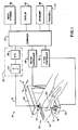
- Fig. 1 is a schematic view of a scanning dual energy x-ray system suitable for use with the present invention showing the placement of the x-ray tube and the x-ray detector.
- Fig. 2 is a graph showing the clock signals controlling the x-ray tube integrator and A/D of Fig. 1.
- a dual energy scanning x-ray machine 10 projects a collimated x-ray beam 12 from an x-ray source 20 along a ray 16 through a patient 18 to an opposed detector 14.
- the x-ray source 20 and detector 14 are mounted on a carriage 22 to move in unison in a raster scan pattern 24 by means of stepper or servo motor (not shown).
- the raster scan pattern 24 sweeps the ray 16 over a rectangular area of the patient 18 by alternately directing it along one of two perpendicular axes x and y of a Cartesian coordinate system with the x-ray beam 12 parallel to a third orthogonal z axis.
- the movement of the carriage 22 is controlled by a motor controller 28 receiving signals from a computer 30.
- the x-ray source 20 includes x-ray tube filters (not shown) to create x-ray emissions.
- Computer 30 also controls the x-ray source 20, turning it on and off and switching voltages and/or filters by means of x-ray controller 32.
- the signal 21 from the detector 14 is received and demultiplexed by integrator 34, digitized by A/D converter 35, and transmitted to computer 30 which stores the data in computer memory (not shown) or on mass storage device 36.
- An operator may provide inputs to the computer 30 by means of keyboard 38 and trackball 40, which allow positioning of a cursor on display screen 42, as is understood in the art.
- the display screen 42 also provides a means of displaying information obtained from the raster scan.
- data are acquired from the detector 14 at each of two x-ray energies produced by the x-ray source 20, as switched by the x-ray controller 32.
- two data samples may be collected, having values corresponding to the absorption by the patient 18 of x-rays 12 at both of the x-ray energies.
- Each pair of samples may be identified to the x and y coordinate of the ray 16, along which the samples were acquired.
- the sample pairs covering the entire raster scan pattern form elements of data matrices whose coordinates correspond to the spatial coordinates of the rays.
- a spacing of 0.6 mm between samples may be obtained over a raster scan area of about 9 by 10 cm.
- the x-ray controller 32 incorporates an internal clock (not shown) for generating a control signal 44, having a high state during periods II, IV and VI, and a low state during periods I, III, and V, for synchronizing the voltage supplied to the x-ray source 20 with the operation of data acquisition system (DAS) 37, comprised of integrator 34 and analog to digital (A/D) converter 35.
- DAS data acquisition system
- A/D analog to digital
- the voltage 46 to the x-ray source 20 when signal 44 is in the high state, the voltage 46 to the x-ray source 20 is increased to a high voltage, V H , for a time period W H and when the signal 44 is in the low state, the voltage 46 to the x-ray source 20 is reduced to a low voltage V L for a time period W L .
- the high and low voltages 46 on the x-ray source 20 refer to the voltage that biases the anode and cathode of the x-ray tube, as is generally understood in the art.
- signal 44 also switches filters used to filter the x-ray beam.
- the changing voltage on the x-ray tube together with the filters, produces the two energy bands of x-ray emissions, as previously described.
- the narrow bands of x-ray emissions will be termed the high and low energy x-ray beams 12, respectively.
- the change in voltage 46 on the x-ray source 20 from a low to a high value will, due to space charge effects, cause an increase in beam current 48.
- the radiation received by detector 14 from x-ray source 20 produces a signal current which is integrated in integrator 34 to produce a signal voltage 50.
- the integrator 34 is cleared at the beginning of time period I, and signal 50 increases during period I in proportion to the radiation intensity being detected by detector 14 in response to the low energy beam 12, dependent on x-ray tube voltage 46, current 48 and the patient 18 being measured.
- a reset signal 52 derived from signal 44 comprises a short logic pulse having a rising edge during the transitions of signal 44 from either low-to-high level or from high-to-low level.
- A/D converter 35 samples and digitizes signal 50, the output of integrator 34. Immediately after the sampling is complete, the pulse in signal 52 clears integrator 34.
- period II the x-ray tube voltage 46 and current 48 are switched to their high states and integrator signal 50 increases at a rate dependent on the radiation intensity being detected by detector 14 in response to the high energy beam 12.
- the signal 50 is digitized at the end of period II.
- periods I and II together produce a pair of x-ray measurements.
- periods III and IV produce a pair of dual energy x-ray measurements, and so on. All of these digitized signals are stored by computer 30.
- the values of integrated signal 50 are shown as being the same at the end of all the high voltage periods (II, IV, VI). Similarly, the values of signal 50 at the end of the low energy periods (I, III, V) are the same. This of course, is not generally the case.
- the values of integrated signal 50 depend on the details of the patient 18 through which beam 12 is transmitted, and on the raster scan movement of the x-ray beam 12.
- Critical to the operation of the present invention is the choice of the time widths of the low and high energy time periods W L and W H , respectively.
- the width of the low energy periods W L controls the integrated intensity of the low energy beam 12 during the low energy periods while W H controls the integrated intensity of the high energy beam 12 during high energy periods.
- W L and W H controls the integrated intensities, and therefore the signal-to-noise ratios of the measurements.
- This independent control of the signal-to-noise ratios of the low and high energy measurements allows optimization of the signal-to-noise ratio of the image of the selected material.
- the exact values of the W H and W L are determined by estimating the average attenuation provided by the patient 18 and adjusting W H and W L to obtain the optimal signal-to-noise ratios in the high and low energy measurements.
- the data at two different x-ray energies associated with the high and low energy x-ray beams 12 can be used to separate the absorption effects of two different body materials at each point of the raster scan pattern 24 and thus to determine the mass of the different materials at each point in the array.
- Algorithms for converting measured x-ray data to selective material measurements are known in the art. See, for example, "Generalized Image Combinations in Dual kVp Digital Radiography" by Lehman, et al., Med. Phys. 8, (5), 1981, or the previously cited article by Sorenson et al.
- W H and W L control signal 44 need not be perfectly periodic. Different values of W L and W H can be used for different parts of the raster scan, for example, if it is known that part of the raster scan will examine the thicker portion of patient 18 than another portion. Also, the present invention can be used in systems which use a fan beam of radiation along with an array of detector elements and one dimensional scanning motion, or with area-beam systems which use no scanning motion at all.
Abstract
Claims (4)
- Dispositif pour l'imagerie sélective de matières d'un objet comprenant au moins une première et une seconde matière comprenant :un tube à rayons X (20) pour recevoir une tension et pour produire un rayonnement à rayons X (12) ayant des caractéristiques spectrales en rapport à la tension ;un contrôle de temporisation pour définir un premier état ayant une première durée et un second état ayant une seconde durée différente de la première durée ;un contrôleur de tube à rayons X (32) pour alimenter le tube a rayons X (20) par une haute tension pendant le premier état et une faible tension pendant le second état ;un détecteur (14) pour recevoir le rayonnement à rayons X du tube à rayons X tel qu'atténué par l'objet et produire un signal électrique proportionnel a l'intensité du rayonnement à rayons X ;un système d'acquisition de données (37) pour recevoir le signal électrique du détecteur et pour produire un premier signal de canal de sortie en rapport à la valeur du signal électrique pendant le premier état et pour produire un second signal de canal de sortie en rapport à la valeur du signal électrique pendant le second état ; etdes moyens (30, 42) pour combiner les premier et second signaux de canaux de sortie pour produire une image représentant sensiblement seulement la première matière,
caractérisé en ce que :le contrôle de temporisation est agencé pour sélectionner la première durée et la seconde durée de sorte que les premier et second signaux de canaux de sortie sont différents pour optimiser de la sorte le rapport signal-bruit de l'image. - Dispositif selon la revendication 1, dans lequel le système d'acquisition de données (37) intègre le signal électrique et dans lequel le premier signal de canal de sortie est proportionnel au rayonnement à rayons X total reçu par le détecteur (14) pendant le premier état et le second signal de canal de sortie est proportionnel au rayonnement à rayons X total reçu par le détecteur (14) pendant le second état.
- Dispositif selon la revendication 2 dans lequel les première et seconde durées sont contrôlées par contré-réaction des premier et second signaux de sortie de canaux.
- Dispositif selon l'une quelconque des revendications précédentes ayant un système à rayons X de balayage pour l'imagerie sélective de matières d'un objet comprenant :un moyen de balayage (22, 28) pour balayer la zone de faisceaux du rayonnement à rayons X (12) à un certain nombre de points sur la zone du patient à une vitesse de balayage.
Applications Claiming Priority (3)
| Application Number | Priority Date | Filing Date | Title |
|---|---|---|---|
| US07/874,146 US5253282A (en) | 1992-04-27 | 1992-04-27 | System for selective material imaging |
| US874146 | 1992-04-27 | ||
| PCT/US1993/003866 WO1993021826A1 (fr) | 1992-04-27 | 1993-04-23 | Systeme pour l'imagerie selective de materiaux |
Publications (2)
| Publication Number | Publication Date |
|---|---|
| EP0594840A1 EP0594840A1 (fr) | 1994-05-04 |
| EP0594840B1 true EP0594840B1 (fr) | 1998-07-01 |
Family
ID=25363080
Family Applications (1)
| Application Number | Title | Priority Date | Filing Date |
|---|---|---|---|
| EP93912350A Expired - Lifetime EP0594840B1 (fr) | 1992-04-27 | 1993-04-23 | Systeme pour l'imagerie selective de materiaux |
Country Status (5)
| Country | Link |
|---|---|
| US (1) | US5253282A (fr) |
| EP (1) | EP0594840B1 (fr) |
| JP (1) | JPH06508055A (fr) |
| DE (1) | DE69319403T2 (fr) |
| WO (1) | WO1993021826A1 (fr) |
Families Citing this family (20)
| Publication number | Priority date | Publication date | Assignee | Title |
|---|---|---|---|---|
| US5490196A (en) * | 1994-03-18 | 1996-02-06 | Metorex International Oy | Multi energy system for x-ray imaging applications |
| US5661774A (en) * | 1996-06-27 | 1997-08-26 | Analogic Corporation | Dual energy power supply |
| US5748704A (en) | 1997-03-10 | 1998-05-05 | Lunar Corporation | Peripheral bone densitometer |
| US5852647A (en) * | 1997-09-24 | 1998-12-22 | Schick Technologies | Method and apparatus for measuring bone density |
| US6510197B1 (en) | 2000-01-11 | 2003-01-21 | Alara, Inc. | Method and apparatus for osteoporosis screening |
| US6449334B1 (en) * | 2000-09-29 | 2002-09-10 | Lunar Corporation | Industrial inspection method and apparatus using dual energy x-ray attenuation |
| JP4334226B2 (ja) * | 2001-02-23 | 2009-09-30 | コーニンクレッカ フィリップス エレクトロニクス エヌ ヴィ | 画像データセットにおいてボリュームの密度を決める方法及びシステム |
| US6636582B2 (en) * | 2001-11-08 | 2003-10-21 | Ge Medical Systems Global Technology Co., Llc | Multiple energy x-ray imaging techniques |
| US6891918B2 (en) * | 2002-11-27 | 2005-05-10 | Ge Medical Systems Global Technology Company, Llc | Methods and apparatus for acquiring perfusion data |
| US6873680B2 (en) * | 2003-05-02 | 2005-03-29 | Siemens Westinghouse Power Corporation | Method and apparatus for detecting defects using digital radiography |
| US6987833B2 (en) * | 2003-10-16 | 2006-01-17 | General Electric Company | Methods and apparatus for identification and imaging of specific materials |
| US20050101970A1 (en) * | 2003-11-06 | 2005-05-12 | Rosenberg William S. | Functional image-guided placement of bone screws, path optimization and orthopedic surgery |
| DE102006014624B4 (de) * | 2006-03-29 | 2008-04-10 | Siemens Ag | Verfahren zur Aufnahme von Projektionsbildern |
| JP5087229B2 (ja) * | 2006-03-30 | 2012-12-05 | 富士フイルム株式会社 | 閉回路テレビカメラのレンズ絞り調整装置 |
| US7742568B2 (en) * | 2007-06-09 | 2010-06-22 | Spectrum San Diego, Inc. | Automobile scanning system |
| US7826587B1 (en) * | 2009-09-11 | 2010-11-02 | General Electric Company | System and method of fast kVp switching for dual energy CT |
| US8314394B1 (en) | 2009-11-04 | 2012-11-20 | Science Applications International Corporation | System and method for three-dimensional imaging using scattering from annihilation coincidence photons |
| US9044186B2 (en) | 2012-06-25 | 2015-06-02 | George W. Ma | Portable dual-energy radiographic X-ray perihpheral bone density and imaging systems and methods |
| DE102012211472A1 (de) * | 2012-07-03 | 2014-01-09 | Siemens Aktiengesellschaft | Verfahren zur Aufnahme von Röntgenbildern und Röntgeneinrichtung |
| KR20140092438A (ko) * | 2012-12-27 | 2014-07-24 | 삼성전자주식회사 | 엑스선 검출 패널, 엑스선 촬영 장치 및 엑스선 영상 생성 방법 |
Family Cites Families (11)
| Publication number | Priority date | Publication date | Assignee | Title |
|---|---|---|---|---|
| DE2304427A1 (de) * | 1973-01-30 | 1974-08-08 | Siemens Ag | Roentgendiagnostikeinrichtung mit mitteln zur veraenderung der roentgenroehrenspannung |
| US3848130A (en) * | 1973-06-25 | 1974-11-12 | A Macovski | Selective material x-ray imaging system |
| US3965358A (en) * | 1974-12-06 | 1976-06-22 | Albert Macovski | Cross-sectional imaging system using a polychromatic x-ray source |
| US4029963A (en) * | 1976-07-30 | 1977-06-14 | The Board Of Trustees Of Leland Stanford Junior University | X-ray spectral decomposition imaging system |
| US4361901A (en) * | 1980-11-18 | 1982-11-30 | General Electric Company | Multiple voltage x-ray switching system |
| US4355331A (en) * | 1981-01-28 | 1982-10-19 | General Electric Company | X-ray image subtracting system |
| US4542459A (en) * | 1982-11-26 | 1985-09-17 | General Electric Company | Matched filter for x-ray hybrid subtraction |
| US4541106A (en) * | 1984-02-22 | 1985-09-10 | General Electric Company | Dual energy rapid switching imaging system |
| US5148455A (en) * | 1986-07-14 | 1992-09-15 | Hologic, Inc. | Bone densitometer |
| US4947414A (en) * | 1986-07-14 | 1990-08-07 | Hologic, Inc. | Bone densitometer |
| US5132995A (en) * | 1989-03-07 | 1992-07-21 | Hologic, Inc. | X-ray analysis apparatus |
-
1992
- 1992-04-27 US US07/874,146 patent/US5253282A/en not_active Expired - Lifetime
-
1993
- 1993-04-23 WO PCT/US1993/003866 patent/WO1993021826A1/fr active IP Right Grant
- 1993-04-23 EP EP93912350A patent/EP0594840B1/fr not_active Expired - Lifetime
- 1993-04-23 DE DE69319403T patent/DE69319403T2/de not_active Expired - Fee Related
- 1993-04-23 JP JP5519419A patent/JPH06508055A/ja active Pending
Also Published As
| Publication number | Publication date |
|---|---|
| EP0594840A1 (fr) | 1994-05-04 |
| DE69319403D1 (de) | 1998-08-06 |
| JPH06508055A (ja) | 1994-09-14 |
| DE69319403T2 (de) | 1998-12-03 |
| WO1993021826A1 (fr) | 1993-11-11 |
| US5253282A (en) | 1993-10-12 |
Similar Documents
| Publication | Publication Date | Title |
|---|---|---|
| EP0594840B1 (fr) | Systeme pour l'imagerie selective de materiaux | |
| US5040199A (en) | Apparatus and method for analysis using x-rays | |
| US4811373A (en) | Bone densitometer | |
| US4947414A (en) | Bone densitometer | |
| US5490196A (en) | Multi energy system for x-ray imaging applications | |
| US6320931B1 (en) | Automated x-ray bone densitometer | |
| US6454460B1 (en) | System and method for evaluating and calibrating a radiation generator | |
| US5148455A (en) | Bone densitometer | |
| US10827992B2 (en) | Energy-discriminating photon-counting detector and the use thereof | |
| US6081582A (en) | Transverse scanning densitometer | |
| JP2002200068A (ja) | 放射線断層撮影装置およびその方法 | |
| US6259766B1 (en) | Computer tomography device | |
| JPS6080746A (ja) | 放射線受像方法 | |
| GB1602521A (en) | Arrangement for producing an image of a body section using gamma or x-radiation | |
| US20040120457A1 (en) | Scatter reducing device for imaging | |
| EP0049464B1 (fr) | Appareil de prise de données radiologiques d'absorption par un appareil de tomographie à ordinateur | |
| US11644587B2 (en) | Pixel summing scheme and methods for material decomposition calibration in a full size photon counting computed tomography system | |
| JP2773358B2 (ja) | 骨塩定量装置 | |
| JPH0921876A (ja) | 改良型ガンマ・カメラ撮像システム | |
| WO2003055393A1 (fr) | Dispositif d'imagerie reducteur de diffusion | |
| CA1292810C (fr) | Appareil de densimetries des os | |
| JPS6343099B2 (fr) | ||
| Tothill | Photon absorptiometry | |
| CN117462151A (zh) | 一种使用多排探测器阵列的全身双能x射线骨密度仪 | |
| JP2001120539A (ja) | マルチスライス検出器を持つx線診断装置 |
Legal Events
| Date | Code | Title | Description |
|---|---|---|---|
| PUAI | Public reference made under article 153(3) epc to a published international application that has entered the european phase |
Free format text: ORIGINAL CODE: 0009012 |
|
| 17P | Request for examination filed |
Effective date: 19940125 |
|
| AK | Designated contracting states |
Kind code of ref document: A1 Designated state(s): AT BE CH DE DK ES FR GB GR IE IT LI LU MC NL PT SE |
|
| RBV | Designated contracting states (corrected) |
Designated state(s): AT BE CH DE DK ES FR GB IT LI LU NL SE |
|
| 17Q | First examination report despatched |
Effective date: 19960726 |
|
| GRAG | Despatch of communication of intention to grant |
Free format text: ORIGINAL CODE: EPIDOS AGRA |
|
| GRAG | Despatch of communication of intention to grant |
Free format text: ORIGINAL CODE: EPIDOS AGRA |
|
| GRAG | Despatch of communication of intention to grant |
Free format text: ORIGINAL CODE: EPIDOS AGRA |
|
| GRAH | Despatch of communication of intention to grant a patent |
Free format text: ORIGINAL CODE: EPIDOS IGRA |
|
| GRAH | Despatch of communication of intention to grant a patent |
Free format text: ORIGINAL CODE: EPIDOS IGRA |
|
| RBV | Designated contracting states (corrected) |
Designated state(s): DE FR GB IT |
|
| GRAA | (expected) grant |
Free format text: ORIGINAL CODE: 0009210 |
|
| AK | Designated contracting states |
Kind code of ref document: B1 Designated state(s): DE FR GB IT |
|
| REF | Corresponds to: |
Ref document number: 69319403 Country of ref document: DE Date of ref document: 19980806 |
|
| ET | Fr: translation filed | ||
| PLBE | No opposition filed within time limit |
Free format text: ORIGINAL CODE: 0009261 |
|
| STAA | Information on the status of an ep patent application or granted ep patent |
Free format text: STATUS: NO OPPOSITION FILED WITHIN TIME LIMIT |
|
| 26N | No opposition filed | ||
| PGFP | Annual fee paid to national office [announced via postgrant information from national office to epo] |
Ref country code: FR Payment date: 20010330 Year of fee payment: 9 |
|
| PGFP | Annual fee paid to national office [announced via postgrant information from national office to epo] |
Ref country code: DE Payment date: 20010402 Year of fee payment: 9 |
|
| PGFP | Annual fee paid to national office [announced via postgrant information from national office to epo] |
Ref country code: GB Payment date: 20010403 Year of fee payment: 9 |
|
| REG | Reference to a national code |
Ref country code: GB Ref legal event code: IF02 |
|
| PG25 | Lapsed in a contracting state [announced via postgrant information from national office to epo] |
Ref country code: GB Free format text: LAPSE BECAUSE OF NON-PAYMENT OF DUE FEES Effective date: 20020423 |
|
| PG25 | Lapsed in a contracting state [announced via postgrant information from national office to epo] |
Ref country code: DE Free format text: LAPSE BECAUSE OF NON-PAYMENT OF DUE FEES Effective date: 20021101 |
|
| GBPC | Gb: european patent ceased through non-payment of renewal fee |
Effective date: 20020423 |
|
| PG25 | Lapsed in a contracting state [announced via postgrant information from national office to epo] |
Ref country code: FR Free format text: LAPSE BECAUSE OF NON-PAYMENT OF DUE FEES Effective date: 20021231 |
|
| REG | Reference to a national code |
Ref country code: FR Ref legal event code: ST |
|
| PGFP | Annual fee paid to national office [announced via postgrant information from national office to epo] |
Ref country code: IT Payment date: 20120424 Year of fee payment: 20 |