EP0594079B1 - Method and apparatus for conveying trays - Google Patents
Method and apparatus for conveying trays Download PDFInfo
- Publication number
- EP0594079B1 EP0594079B1 EP93116712A EP93116712A EP0594079B1 EP 0594079 B1 EP0594079 B1 EP 0594079B1 EP 93116712 A EP93116712 A EP 93116712A EP 93116712 A EP93116712 A EP 93116712A EP 0594079 B1 EP0594079 B1 EP 0594079B1
- Authority
- EP
- European Patent Office
- Prior art keywords
- station
- tray
- loaded
- situated
- waiting
- Prior art date
- Legal status (The legal status is an assumption and is not a legal conclusion. Google has not performed a legal analysis and makes no representation as to the accuracy of the status listed.)
- Expired - Lifetime
Links
Images


Classifications
-
- B—PERFORMING OPERATIONS; TRANSPORTING
- B65—CONVEYING; PACKING; STORING; HANDLING THIN OR FILAMENTARY MATERIAL
- B65G—TRANSPORT OR STORAGE DEVICES, e.g. CONVEYORS FOR LOADING OR TIPPING, SHOP CONVEYOR SYSTEMS OR PNEUMATIC TUBE CONVEYORS
- B65G47/00—Article or material-handling devices associated with conveyors; Methods employing such devices
- B65G47/52—Devices for transferring articles or materials between conveyors i.e. discharging or feeding devices
-
- B—PERFORMING OPERATIONS; TRANSPORTING
- B65—CONVEYING; PACKING; STORING; HANDLING THIN OR FILAMENTARY MATERIAL
- B65G—TRANSPORT OR STORAGE DEVICES, e.g. CONVEYORS FOR LOADING OR TIPPING, SHOP CONVEYOR SYSTEMS OR PNEUMATIC TUBE CONVEYORS
- B65G35/00—Mechanical conveyors not otherwise provided for
- B65G35/06—Mechanical conveyors not otherwise provided for comprising a load-carrier moving along a path, e.g. a closed path, and adapted to be engaged by any one of a series of traction elements spaced along the path
-
- B—PERFORMING OPERATIONS; TRANSPORTING
- B65—CONVEYING; PACKING; STORING; HANDLING THIN OR FILAMENTARY MATERIAL
- B65G—TRANSPORT OR STORAGE DEVICES, e.g. CONVEYORS FOR LOADING OR TIPPING, SHOP CONVEYOR SYSTEMS OR PNEUMATIC TUBE CONVEYORS
- B65G60/00—Simultaneously or alternatively stacking and de-stacking of articles
Description
- This invention relates to a tray conveying method and apparatus in which for automatically attaching pull tabs to slide fastener sliders, a large number of trays each accommodating the pull tabs in row are previously stocked in stack, the loaded trays are supplied to a working station one at a time from the lowermost one of the stack, and the empty trays are collected.
- In conventional automatic assembling machines, it has been a common practice to use a bowl hopper feeder as a means for supplying pull tabs for slide fastener sliders. With this conventional feeder, the shape of the pull tabs which can be supplied in row is limited to a plate-like shape different between upper and lower portions but identical between front and rear sides. If the form or design of the pull tabs is different between front and rear sides in view of fashionability or if the pull tabs have a unique form equipped with rubber, they cannot be supplied by the feeder. In the case where such unique pull tabs are to be supplied, it has been proposed to previously place the pull tabs in row on a tray and to convey the tray.
- In a generally known tray conveying method, however, from the waiting station where a large number of loaded trays are placed in stack, the lowermost loaded tray is separated and is then supplied to the working station where parts are supplied to the automatic assembling machine by a robot or other means, and when the tray is emptied, the empty tray is discharged to the collecting station in opposite to the waiting station. This known method is exemplified by Japanese Patent Laid-Open Publication No. SHO 63-247221.
- According to the conventional conveying method, the waiting, working and collecting stations are arranged basically in a row, and the row requires at least such a length that the trays to be conveyed can be placed in the individual stations. Assuming that this method is carried out by, for example, a rotary-table automatic assembling machine, various kinds of units are situated about a rotary table, each unit being located tangentially with respect to the rotary table to avoid any interference with adjacent units. This makes the distance between the working station and the placing station of the rotary table larger; as a result, when the parts are placed by a robot or other means, the extent to which the robot's arm is to be angularly moved will be greater so that it will take more time to supply the parts for assembling. Thus since such placing operation of the parts to the rotary table would take more time than placing operation of other parts, it is necessary to reduce the rate of rotation of the rotary table.
- It is an object of this invention to provide a tray conveying method and apparatus in which for supplying parts using trays, the supplying position can be situated as near to the placing and working position as possible and in which an empty tray and a loaded tray can be exchanged with each other quickly.
- According to a first aspect of the invention, there is provided a method of conveying trays along a supply path and a discharge path which is situated under the supply path in parallel through a waiting station situated at one end of the supply path, a working station situated at the other end of the supply path, a switching station situated in the discharge path under the waiting station, a shunting station situated under the working station, a stocking station situated above the waiting station, and a collecting station situated under the switching station, which method comprising the steps of: conveying a loaded tray, which accomodates a plurality of parts in rows, from the waiting station to the working station along the supply path; simultaneously with the conveying, returning an empty tray, which is supported in the shunting station, to the switching station along the discharge path; raising the empty tray, which has been returned to the switching station, up to the stocking station, supporting a large number of loaded trays in stack on the raised empty tray in the stocking station, and then lowering the empty tray down to the collecting station; during the lowering step, supporting the stack of loaded trays except the lowermost loaded tray again in the stocking station; supporting the loaded tray, which is left on the empty tray, in the waiting station; during the last-named supporting step, lowering the emptied tray in the working station to the shunting station; and repeating the foregoing steps in order.
- According to a second aspect of the invention, there is provided an apparatus for conveying trays, comprising: a stocking station in which a large number of loaded trays each accommodating a plurality of parts in rows are to be supported in stack and are to be released individually; a waiting station which is situated under said stocking station and in which the loaded tray separated from the stack of loaded trays is to be supported and released; a switching station which is situated under the waiting station and in which an empty tray is to be supported and released; a collecting station which is situated under the switching station and in which a large number of the empty trays are to be placed in stack, the collecting station being adapted to be raised to and lowered from the stocking station via the switching station and the waiting station by a separating lifter; a working station which is situated at a forward end of a supply path extending from the waiting station and in which the tray is to be supported and released; a shunting station which is situated under the working station and in which the tray is to be supported and released; a receiving plate which is situated under the shunting station for supporting the tray and which is adapted to be raised to and from the working station by a transferring lifter; and a discharge path situated between the shunting station and the switching station.
- The above mentioned operation is repeated to convey the trays continuously. Therefore, a large number of loaded trays are stocked in stack in the stocking station, and when a loaded tray separated from the stack is supported in the waiting station situated under the stocking station, another loaded tray already supplied is existing in the working station. When the tray in the working station is emptied, the empty tray will be lowered to and supported in the shunting station, whereupon the loaded tray in the waiting station will be supplied to the working station and, at the same time, the empty tray in the shunting station will be returned to the switching station.
- While the parts are loaded into an automatic assembling machine from the loaded tray in the working station, the collecting station is raised to support on the collecting station the empty tray in the switching station and also to support on the empty tray the loaded trays in stack.
- Subsequently, the collecting station with the empty and loaded trays supported thereon will be lowered, during which the stack of loaded trays except the lowermost one will be supported in the stocking station, and the separated lowermost loaded tray with the empty tray will be lowered beyond the stocking station. During the last-mentioned lowering, the separated loaded tray will be supported in the waiting station, and the collecting station with the empty tray supported thereon will be lowered to a predetermined position.
- Thus when the tray in the working station has been emptied, the foregoing steps will be repeated.
-
- FIG. 1 is a schematic side view showing an apparatus for carrying out a tray conveying method according to this invention;
- FIG. 2 is a plan view of FIG. 1;
- FIG. 3 shows the apparatus when an empty tray is transferred from the working station to the shunting station;
- FIG. 4 shows the apparatus when a loaded tray and an empty tray are conveyed to the working station and the switching station, respectively;
- FIG. 5 shows the apparatus in the initial stage when a loaded tray is separated from a stack of loaded trays;
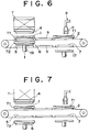
- FIG. 6 shows the manner in which the separated loaded tray is supported in the waiting station;
- FIG. 7 shows the apparatus when an empty tray is conveyed to the collecting station;
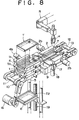
- FIG. 8 is a schematic perspective view of a tray conveying apparatus according to this invention; and
- FIG. 9 is a front view of the tray conveying apparatus according to the invention.
- An embodiment of this invention will now be described with reference to the accompanying drawings. As shown in FIGS. 1, 2, 8 and 9, a
supply path 3 is situated between awaiting station 1, in which a loaded tray T1 is to be supported, and aworking station 2, which is situated at the front end of an horizontal extension of thewaiting station 1 and in which likewise a loaded tray T1 is to be supported. Astocking station 4, in which a large number of loaded trays T1 are to be stocked in stack, is situated above thewaiting station 1, and aswitching station 5 is situated under thewaiting station 1. Under theswitching station 5, acollecting station 6 is situated. On the other hand, ashunting station 7 is situated under theworking station 2, and adischarge path 8 situated between theshunting station 7 and theswitching station 5. In theworking station 2, parts in the loaded tray T1 are loaded to, for example, an automatic assembling machine by a hand H of a robot R. The shape of the individual trays is such that when they are placed in stack, a part of the bottom of an upper tray will be received in a lower next tray. - Each of the stocking, waiting and switching
stations supply path 3 is composed, as shown in FIG. 9, of a horizontal pair ofsupport members support members supply path 3 by a respective pair ofcylinders - The working and
shunting stations supply path 3 are composed, as shown in FIG. 8, of a horizontal pair of support members each having a generally C-shape cross section, opening to each other. The upperhorizontal portions 2a of the support member pair constitute theworking station 2, while the lowerhorizontal portions 7a of the same support member pair constitute theshunting station 7. The upperhorizontal portions 2a are spaced apart normally by such a distance as to support the tray and can be spread horizontally in the longitudinal direction of thesupply path 3 by a respective pair ofcylinders 2b to release the tray. - The supply and
discharge paths waiting station 1 and theworking station 2 is composed, as shown in FIGS. 1 and 8, of a horizontal pair offixed guides 9 each having a generally C-shape cross section, opening to each other. The upper horizontal portions of thefixed guide pair 9 is arranged in horizontal alignment with the support members 1a of thewaiting station 1 and the upperhorizontal portions 2a of theworking station 2 to constitute thesupply path 3. On the other hand, the lower horizontal portions of thefixed guide pair 9 is arranged in horizontal alignment with the lowerhorizontal portions 7a of theshunting station 7 and thesupport members 5a of theswitching station 5 to constitute thedischarge path 8. - The tray is conveyed onto the
supply path 3 and thedischarge path 8 by aconveyer 10. Theconveyer 10 includes, as shown in FIG. 8, a horizontal drivenshaft 11 situated at one end of a tray conveying path, ahorizontal follower shaft 12 situated at the other end of the tray conveying path, and a pair ofendless belts follower shafts fixed guide 9 and the upper horizontal portion of theworking station 2, while the lower portion of the individual belt passes under the lowerhorizontal portion 7a of theshunting station 7, the lower horizontal portion of thefixed guide 9, thesupport member 5a of theswitching station 5. On the upper and lower sides of eachendless belt 13, two pairs ofpushers shaft 11 is connected with amotor 16. - As the
motor 16 is energized, a loaded tray T1 supported in thewaiting station 1 is conveyed to theworking station 2 via the upper horizontal portions of thefixed guides 9 and, at the same time, an empty tray T2 supported in theshunting station 7 is returned to theswitching station 5 via the lower horizontal portions of thefixed guides 9. - In order to convey the emptied tray in the
working station 2 to theshunting station 7, as shown in FIGS. 1 and 8, areceiving plate 17 is situated under theshunting station 7 and is vertically movable by a transferringlifter 18, such as a cylinder. Thereceiving plate 17 has such a width that it can pass through the space between the upperhorizontal portions 2a of theworking station 2 and between the lowerhorizontal portions 7a of theshunting station 7 while they are supporting the tray. - Therefore, in transferring the empty tray T2 from the
working station 2 to theshunting station 7, if thereceiving plate 17 is raised, it will pass theshunting station 7 as nothing is supported in theshunting station 7. The empty tray T2 in theworking station 2 is then placed on thereceiving plate 17. After the upperhorizontal portions 2a of theworking station 2 are spread apart by thecylinders 2b (at the same time, the lowerhorizontal portions 7a of theshunting station 7 are spread apart), thereceiving plate 17 is lowered so that the empty tray T2 on thereceiving plate 17 will be horizontally aligned with the lowerhorizontal portions 7a of theshunting station 7 and, at the same time, the lowerhorizontal portions 7a are returned to the original position (at the same time, the upperhorizontal portions 2a are returned to the original position). As a result, the empty tray T2 will be supported on the lowerhorizontal portions 7a, and thereceiving plate 17 will be lowered until it reaches a predetermined position. - At the base-end side of the
supply path 3, in order to separate the lowermost loaded tray T1 from a stack of loaded trays T on thestocking station 4 and to transfer the separated loaded tray T1 to the waitingstation 1, the collectingstation 6 can be raised to and lowered from the stockingstation 4 by aseparating lifter 19 as shown in FIGS. 1 and 8. The collectingstation 6 is in the form of a plate to be moved vertically by theseparating lifter 19 and having such a size that it can pass through the space of each of the waiting and stockingstations - The above-mentioned separating, as shown in FIGS. 4 through 7, takes place after the empty tray T2 has been returned to the switching
station 5. Firstly as theseparating lifter 19 is driven, the plate of the collectingstation 6 is raised to receive on it the empty tray T2 supported in the switchingstation 5. With continued raising of the collectingstation 6, it passes the waitingstation 1, where nothing is supported, until it reaches thestocking station 4 to support the loaded trays T, which are stocked in stack in thestocking station 4, on the empty tray T2. During the raising of the plate, each of the switching, waiting and stockingstations station 4, and at the same time, the stockingstation 4 is returned to the original position to support the stack of loaded trays T again. At that time, on the plate, a loaded tray T1 is placed on the empty tray T2, and the plate with the loaded tray T1 on the empty tray T2 is then lowered. On the downward way of the plate, the loaded tray T1 is horizontally aligned with the waitingstation 1, and at the same time, thespread waiting station 1 is closed to support the loaded tray T1. At that time, only the empty tray T2 is placed on the plate. The plate is lowered beyond the switchingstation 5 until it reaches a predetermined position. - As is mentioned above, when the loaded tray T1 supplied to the working
station 2 has been emptied, the empty tray T2 is lowered to the shunting station 7 (FIG. 3) and is then returned to the switching station 5 (FIG. 4), whereupon the empty tray T2 is raised (FIG. 5) and the stack of loaded trays T are supported on the empty tray T2. Then the empty tray T2 is lowered, and on its downward way, the stack of loaded trays T except the lowermost loaded tray are supported in thestocking station 4. And the loaded tray T1 placed on the empty tray T2 is supported in the waiting station 1 (FIG. 6), and the empty tray T2 is supported and held on the collecting station 6 (FIG. 7). By repeating the foregoing steps, successive empty trays are held in stack on the collectingstation 6. - As the successive empty trays T2 are placed in stack on the collecting
station 6, the stack increases in height; but the upward and downward stroke of the collectingstation 6 has to be kept constant. Consequently the level at which the uppermost empty tray T2 of the stack on the plate of the collectingstation 6 is to be stopped is detected by a sensor (not shown). - As the foregoing steps are repeated, the amount of loaded trays T stocked in stack on the
stocking station 4 will be reduced gradually, and on the other hand, the number of emptied trays in the collectingstation 6 is increased one by one. Consequently a control unit (not shown) stops the operation of the apparatus when the loaded tray T in thestocking station 4 are used up or when the number of empty trays in the collectingstation 6 reaches a predetermined value. If continuous supply of parts is necessary, the amount of stack in the stocking and collectingstations - As shown in FIG. 2, two
levers fixed guides 9 for positioning the trays T1 precisely in the waiting and workingstations - According to this invention, the tray conveying method comprises the steps of: conveying a loaded tray, which accommodates a plurality of parts in rows, from the waiting station to the working station along the supply path; simultaneously with the conveying, returning an empty tray, which is supported in the shunting station, to the switching station along the discharge path; raising the empty tray, which has been returned to the switching station, up to the stocking station, supporting a large number of loaded trays in stack on the raised empty tray in the stocking station, and then lowering the empty tray down to the collecting station; during the lowering step, supporting the stack of loaded trays except the lowermost loaded tray again in the stocking station; supporting the loaded tray, which is left on the empty tray, in the waiting station; and lowering the emptied tray in the working station to the shunting station, during the last-named supporting step. This method causes the following results.
- Since when the loaded tray in the working station is emptied, the empty tray will be lowered and instantly the next loaded tray will be supplied, it is possible to pick up the individual parts so as to load them to an automatic assembling machine continuously.
- Since the method includes returning the empty tray downwardly of the stocking station, vertically moving the empty tray there, separating a loaded tray from the stack of loaded trays and collecting the empty tray, it is possible to facilitate automation of these steps. Further since the space of each of the stocking, waiting and switching stations has only such a width that the trays can be supported in the individual station, it is possible to perform the separating step quickly.
- According to the tray conveying apparatus of this invention, a supply path and a discharge path are situated on the upper and lower sides, respectively, of the apparatus. The stocking, waiting, switching and collecting stations are arranged one under the other in order on the base-end side of the supply path. The waiting station is situated on the supply path, while the switching station is situated on the discharge path. The working station is situated on the front-end side of the supply path, and the shunting station is situated under the working station on the discharge path. Each of the stocking, waiting, switching, working and shunting stations is so constructed as to support and release the tray. The collecting station is vertically movable by the separating lifter, and the receiving plate under the shunting station is vertically movable by the transferring lifter. This arrangement causes the following results.
- Partly since the transferring of the loaded tray and the returning of the empty tray take place simultaneously, and partly since the empty tray is returned downwardly of the stocking station, it is possible to provide the working station on the front end of the supply path so that the working station can be situated near an automatic assembling machine or the like.
- While the collecting station is vertically moved by the separating lifter, the stocking, waiting and switching stations are opened and closed successively to support and release the tray so that the lowermost loaded tray can be separated from the stack of loaded trays and can be supported in the waiting station and so that the empty tray can be held in the collecting station. Partly since these movements are simple motions including a rectilinear reciprocating motion and a right vertical motion, and partly since the trays are kept to have horizontal postures and kept from being inclined during the separating, it is possible to hold parts in the tray surely in row without being disordered. Further it is possible to make the structure of the apparatus simple and small-sized.
- Since the receiving plate is vertically moved by the transferring lifter when removing the emptied tray from the working station, it is possible to remove the empty tray without being inclined, so that the stack of loaded trays can be supported surely on the empty tray and a large number of empty trays can be placed in stack on the collecting station orderly.
Claims (2)
- A method of conveying trays along a supply path (3) and a discharge path (8) which is situated under said supply path (3) in parallel through a waiting station (1) situated at one end of said supply path (3), a working station (2) situated at the other end of the supply path (3), a switching station (5) situated in said discharge path (8) under the waiting station (1), a shunting station (7) situated under the working station (2), a stocking station (4) situated above the waiting station (1), and a collecting station (6) situated under the switching station (5), said method comprising the steps of:(a) conveying a loaded tray (T1), which accommodates a plurality of parts in rows, from the waiting station (1) to the working station (2) along the supply path (3);(b) simultaneously with said conveying, returning an empty tray (T2), which is supported in the shunting station (7), to the switching station (5) along the discharge path (8);(c) raising the empty tray (T2), which has been returned to the switching station (5), up to the stocking station (4), supporting a large number of loaded trays (T) in stack on the raised empty tray (T2) in the stocking station (4), and then lowering the empty tray (T2) down to the collecting station (6);(d) supporting, during said lowering step, the stack of loaded trays (T) except the lowermost loaded tray (T) again in the stocking station (4);(e) supporting the loaded tray (T1), which is left on the empty tray (T2), in the waiting station (1);(f) lowering the emptied tray (T1) in the working station (2) to the shunting station (7) during the last-named supporting step; and(g) repeating the foregoing steps in order.
- An apparatus for conveying trays, comprising:(a) a stocking station (4) in which a large number of loaded trays (T1) each accommodating a plurality of parts in rows are to be supported in stack and are to be released individually;(b) a waiting station (1) which is situated under said stocking station (4) and in which the loaded tray (T1) separated from the stack of loaded trays (T) is to be supported and released;(c) a switching station (5) which is situated under said waiting station (1) and in which an empty tray (T2) is to be supported and released;(d) a collecting station (6) which is situated under said switching station (5) and in which a large number of the empty trays (T2) are to be placed in stack, said collecting station (6) being adapted to be raised to and lowered from said stocking station (4) via said switching station (5) and said waiting station (1) by a separating lifter (19);(e) a working station (2) which is situated at a forward end of a supply path (3) extending from said waiting station (1) and in which the tray is to be supported and released;(f) a shunting station (7) which is situated under said working station (2) and in which the tray is to be supported and released;(g) a receiving plate (17) which is situated under said shunting station (7) for supporting the tray and which is adapted to be raised to and lowered from said working station (2) by a transferring lifter (18); and(h) a discharge path (8) situated between said shunting station (7) and said switching station (5).
Applications Claiming Priority (2)
| Application Number | Priority Date | Filing Date | Title |
|---|---|---|---|
| JP308100/92 | 1992-10-21 | ||
| JP4308100A JPH06127672A (en) | 1992-10-21 | 1992-10-21 | Tray transport method and its device |
Publications (2)
| Publication Number | Publication Date |
|---|---|
| EP0594079A1 EP0594079A1 (en) | 1994-04-27 |
| EP0594079B1 true EP0594079B1 (en) | 1996-12-18 |
Family
ID=17976869
Family Applications (1)
| Application Number | Title | Priority Date | Filing Date |
|---|---|---|---|
| EP93116712A Expired - Lifetime EP0594079B1 (en) | 1992-10-21 | 1993-10-15 | Method and apparatus for conveying trays |
Country Status (8)
| Country | Link |
|---|---|
| EP (1) | EP0594079B1 (en) |
| JP (1) | JPH06127672A (en) |
| KR (1) | KR0141351B1 (en) |
| CA (1) | CA2108393C (en) |
| DE (1) | DE69306730T2 (en) |
| ES (1) | ES2095546T3 (en) |
| HK (1) | HK128197A (en) |
| SG (1) | SG44874A1 (en) |
Families Citing this family (13)
| Publication number | Priority date | Publication date | Assignee | Title |
|---|---|---|---|---|
| JP2005343605A (en) * | 2004-06-01 | 2005-12-15 | Star Seiki Co Ltd | Container supply carrying-out device and its method |
| JP4854077B2 (en) * | 2006-07-21 | 2012-01-11 | 富士機械製造株式会社 | Transport device |
| CN103183213B (en) * | 2013-03-21 | 2015-03-18 | 苏州凯蒂亚半导体制造设备有限公司 | Automatic cycle conveyor |
| CN103434835B (en) * | 2013-09-11 | 2015-12-23 | 津伦(天津)精密机械股份有限公司 | There is lifting function can pick and place exemplar workpiece conveyor of leaking hunting from roller-way shelf |
| CN106078229B (en) * | 2016-07-08 | 2019-03-12 | 福建龙净环保股份有限公司 | Electric precipitator positive plate production line |
| CN106276211A (en) * | 2016-08-31 | 2017-01-04 | 苏州朗坤自动化设备有限公司 | A kind of Tray disk-transporting device |
| CN106708000B (en) * | 2017-02-23 | 2023-06-13 | 通用技术集团昆明机床股份有限公司 | Flexible manufacturing system |
| CN107052745A (en) * | 2017-03-21 | 2017-08-18 | 无锡奥特维智能装备有限公司 | Pipeline |
| CN106829468A (en) * | 2017-03-21 | 2017-06-13 | 无锡奥特维智能装备有限公司 | Battery core feeding system |
| KR102027774B1 (en) * | 2018-03-08 | 2019-10-02 | (주)에치씨엘 | A tray automatic feeder |
| CN109367883A (en) * | 2018-10-27 | 2019-02-22 | 福建南安市华天机械有限公司 | Diamond segment automatic packaging machine |
| CN113291788A (en) * | 2021-05-13 | 2021-08-24 | 成都华远焊割设备有限公司 | Automatic robot carrying system and operation method thereof |
| CN114435937A (en) * | 2021-12-29 | 2022-05-06 | 上海新松机器人有限公司 | Material transfer system and application system thereof |
Family Cites Families (4)
| Publication number | Priority date | Publication date | Assignee | Title |
|---|---|---|---|---|
| JPS60171927A (en) * | 1984-02-17 | 1985-09-05 | Matsushita Electric Ind Co Ltd | Container carrying device |
| JPS6118623A (en) * | 1984-06-29 | 1986-01-27 | Brother Ind Ltd | Conveying apparatus |
| US4671402A (en) * | 1985-03-26 | 1987-06-09 | Sanshin Shokai Co., Ltd. | Free flow conveyor |
| FR2607793A1 (en) * | 1986-12-05 | 1988-06-10 | Pages Ind | Chain conveyor comprising a device for transferring objects carried by the upper strands (carrying runs) onto the lower strands (return belt), and vice versa |
-
1992
- 1992-10-21 JP JP4308100A patent/JPH06127672A/en active Pending
-
1993
- 1993-10-14 CA CA002108393A patent/CA2108393C/en not_active Expired - Fee Related
- 1993-10-15 DE DE69306730T patent/DE69306730T2/en not_active Expired - Fee Related
- 1993-10-15 EP EP93116712A patent/EP0594079B1/en not_active Expired - Lifetime
- 1993-10-15 ES ES93116712T patent/ES2095546T3/en not_active Expired - Lifetime
- 1993-10-15 SG SG1996008947A patent/SG44874A1/en unknown
- 1993-10-20 KR KR1019930021860A patent/KR0141351B1/en not_active IP Right Cessation
-
1997
- 1997-06-26 HK HK128197A patent/HK128197A/en not_active IP Right Cessation
Also Published As
| Publication number | Publication date |
|---|---|
| DE69306730T2 (en) | 1997-10-30 |
| SG44874A1 (en) | 1997-12-19 |
| EP0594079A1 (en) | 1994-04-27 |
| CA2108393A1 (en) | 1994-04-22 |
| ES2095546T3 (en) | 1997-02-16 |
| KR940008625A (en) | 1994-05-16 |
| DE69306730D1 (en) | 1997-01-30 |
| HK128197A (en) | 1997-09-19 |
| JPH06127672A (en) | 1994-05-10 |
| CA2108393C (en) | 1996-12-10 |
| KR0141351B1 (en) | 1998-07-15 |
Similar Documents
| Publication | Publication Date | Title |
|---|---|---|
| EP0594079B1 (en) | Method and apparatus for conveying trays | |
| US7156220B2 (en) | Automatic tray handling system for sorter | |
| US4541762A (en) | Apparatus for loading and/or unloading machine tools or the like | |
| US6220424B1 (en) | Method and apparatus for transferring items from a conveyor | |
| JPH07232828A (en) | Parts supply device | |
| US5441380A (en) | Method and apparatus for conveying trays | |
| EP0598397B1 (en) | Goods discharge unit for and method of discharging goods from a conveyor apparatus | |
| CA1325816C (en) | System for removing press-formed parts | |
| US4090618A (en) | Device for inserting spacing strips between boards to be stacked | |
| JP3827390B2 (en) | Conveyor merging device for trays with agricultural products | |
| EP0181987A1 (en) | Machine for stacking bundles of signatures and like products | |
| US5083411A (en) | Apparatus for unstacking, filling and stacking containers which are the same as each other | |
| CN112811198A (en) | Intelligent stacking and separating device | |
| EP0480533A1 (en) | Block filling apparatus | |
| JPH0134886B2 (en) | ||
| US6397563B1 (en) | Method and device for packaging flat products | |
| KR950014422B1 (en) | Apparatus for arraying parts on respective trays | |
| US4671401A (en) | Method of and apparatus for conveying articles | |
| KR102546254B1 (en) | Egg Tray High Speed Transfer Device | |
| CN114030670A (en) | Automatic packaging machine for arranging and sorting bar materials | |
| JPS63202521A (en) | Tray feeding/discharging device | |
| EP0780069B1 (en) | A brush body feeding device | |
| US5090687A (en) | Method of sorting printing plates | |
| EP0410732B1 (en) | Lithographic plate storing system | |
| JP3447790B2 (en) | Parts supply device |
Legal Events
| Date | Code | Title | Description |
|---|---|---|---|
| PUAI | Public reference made under article 153(3) epc to a published international application that has entered the european phase |
Free format text: ORIGINAL CODE: 0009012 |
|
| AK | Designated contracting states |
Kind code of ref document: A1 Designated state(s): BE DE ES FR GB IT NL |
|
| 17P | Request for examination filed |
Effective date: 19940726 |
|
| RAP1 | Party data changed (applicant data changed or rights of an application transferred) |
Owner name: YKK CORPORATION |
|
| GRAG | Despatch of communication of intention to grant |
Free format text: ORIGINAL CODE: EPIDOS AGRA |
|
| 17Q | First examination report despatched |
Effective date: 19960216 |
|
| GRAH | Despatch of communication of intention to grant a patent |
Free format text: ORIGINAL CODE: EPIDOS IGRA |
|
| GRAH | Despatch of communication of intention to grant a patent |
Free format text: ORIGINAL CODE: EPIDOS IGRA |
|
| GRAA | (expected) grant |
Free format text: ORIGINAL CODE: 0009210 |
|
| AK | Designated contracting states |
Kind code of ref document: B1 Designated state(s): BE DE ES FR GB IT NL |
|
| ET | Fr: translation filed | ||
| ITF | It: translation for a ep patent filed |
Owner name: JACOBACCI & PERANI S.P.A. |
|
| REF | Corresponds to: |
Ref document number: 69306730 Country of ref document: DE Date of ref document: 19970130 |
|
| REG | Reference to a national code |
Ref country code: ES Ref legal event code: FG2A Ref document number: 2095546 Country of ref document: ES Kind code of ref document: T3 |
|
| PGFP | Annual fee paid to national office [announced via postgrant information from national office to epo] |
Ref country code: ES Payment date: 19971002 Year of fee payment: 5 |
|
| PGFP | Annual fee paid to national office [announced via postgrant information from national office to epo] |
Ref country code: GB Payment date: 19971006 Year of fee payment: 5 |
|
| PLBE | No opposition filed within time limit |
Free format text: ORIGINAL CODE: 0009261 |
|
| STAA | Information on the status of an ep patent application or granted ep patent |
Free format text: STATUS: NO OPPOSITION FILED WITHIN TIME LIMIT |
|
| PGFP | Annual fee paid to national office [announced via postgrant information from national office to epo] |
Ref country code: NL Payment date: 19971031 Year of fee payment: 5 |
|
| PGFP | Annual fee paid to national office [announced via postgrant information from national office to epo] |
Ref country code: DE Payment date: 19971127 Year of fee payment: 5 |
|
| 26N | No opposition filed | ||
| PGFP | Annual fee paid to national office [announced via postgrant information from national office to epo] |
Ref country code: FR Payment date: 19980721 Year of fee payment: 6 |
|
| PGFP | Annual fee paid to national office [announced via postgrant information from national office to epo] |
Ref country code: BE Payment date: 19980727 Year of fee payment: 6 |
|
| PG25 | Lapsed in a contracting state [announced via postgrant information from national office to epo] |
Ref country code: GB Free format text: LAPSE BECAUSE OF NON-PAYMENT OF DUE FEES Effective date: 19981015 |
|
| PG25 | Lapsed in a contracting state [announced via postgrant information from national office to epo] |
Ref country code: ES Free format text: LAPSE BECAUSE OF THE APPLICANT RENOUNCES Effective date: 19981016 |
|
| PG25 | Lapsed in a contracting state [announced via postgrant information from national office to epo] |
Ref country code: NL Free format text: LAPSE BECAUSE OF NON-PAYMENT OF DUE FEES Effective date: 19990501 |
|
| GBPC | Gb: european patent ceased through non-payment of renewal fee |
Effective date: 19981015 |
|
| NLV4 | Nl: lapsed or anulled due to non-payment of the annual fee |
Effective date: 19990501 |
|
| PG25 | Lapsed in a contracting state [announced via postgrant information from national office to epo] |
Ref country code: DE Free format text: LAPSE BECAUSE OF NON-PAYMENT OF DUE FEES Effective date: 19990803 |
|
| PG25 | Lapsed in a contracting state [announced via postgrant information from national office to epo] |
Ref country code: BE Free format text: LAPSE BECAUSE OF NON-PAYMENT OF DUE FEES Effective date: 19991031 |
|
| BERE | Be: lapsed |
Owner name: YKK CORP. Effective date: 19991031 |
|
| PG25 | Lapsed in a contracting state [announced via postgrant information from national office to epo] |
Ref country code: FR Free format text: LAPSE BECAUSE OF NON-PAYMENT OF DUE FEES Effective date: 20000630 |
|
| REG | Reference to a national code |
Ref country code: FR Ref legal event code: ST |
|
| REG | Reference to a national code |
Ref country code: ES Ref legal event code: FD2A Effective date: 20001009 |
|
| PG25 | Lapsed in a contracting state [announced via postgrant information from national office to epo] |
Ref country code: IT Free format text: LAPSE BECAUSE OF NON-PAYMENT OF DUE FEES;WARNING: LAPSES OF ITALIAN PATENTS WITH EFFECTIVE DATE BEFORE 2007 MAY HAVE OCCURRED AT ANY TIME BEFORE 2007. THE CORRECT EFFECTIVE DATE MAY BE DIFFERENT FROM THE ONE RECORDED. Effective date: 20051015 |