EP0594045A1 - Vehicle tyre tread - Google Patents
Vehicle tyre tread Download PDFInfo
- Publication number
- EP0594045A1 EP0594045A1 EP93116535A EP93116535A EP0594045A1 EP 0594045 A1 EP0594045 A1 EP 0594045A1 EP 93116535 A EP93116535 A EP 93116535A EP 93116535 A EP93116535 A EP 93116535A EP 0594045 A1 EP0594045 A1 EP 0594045A1
- Authority
- EP
- European Patent Office
- Prior art keywords
- tread
- hysteresis
- contact
- braking distance
- radially
- Prior art date
- Legal status (The legal status is an assumption and is not a legal conclusion. Google has not performed a legal analysis and makes no representation as to the accuracy of the status listed.)
- Withdrawn
Links
Images

Classifications
-
- B—PERFORMING OPERATIONS; TRANSPORTING
- B60—VEHICLES IN GENERAL
- B60C—VEHICLE TYRES; TYRE INFLATION; TYRE CHANGING; CONNECTING VALVES TO INFLATABLE ELASTIC BODIES IN GENERAL; DEVICES OR ARRANGEMENTS RELATED TO TYRES
- B60C11/00—Tyre tread bands; Tread patterns; Anti-skid inserts
- B60C11/14—Anti-skid inserts, e.g. vulcanised into the tread band
- B60C11/18—Anti-skid inserts, e.g. vulcanised into the tread band of strip form, e.g. metallic combs, rubber strips of different wear resistance
-
- B—PERFORMING OPERATIONS; TRANSPORTING
- B60—VEHICLES IN GENERAL
- B60C—VEHICLE TYRES; TYRE INFLATION; TYRE CHANGING; CONNECTING VALVES TO INFLATABLE ELASTIC BODIES IN GENERAL; DEVICES OR ARRANGEMENTS RELATED TO TYRES
- B60C11/00—Tyre tread bands; Tread patterns; Anti-skid inserts
-
- B—PERFORMING OPERATIONS; TRANSPORTING
- B60—VEHICLES IN GENERAL
- B60C—VEHICLE TYRES; TYRE INFLATION; TYRE CHANGING; CONNECTING VALVES TO INFLATABLE ELASTIC BODIES IN GENERAL; DEVICES OR ARRANGEMENTS RELATED TO TYRES
- B60C11/00—Tyre tread bands; Tread patterns; Anti-skid inserts
- B60C11/0041—Tyre tread bands; Tread patterns; Anti-skid inserts comprising different tread rubber layers
- B60C11/005—Tyre tread bands; Tread patterns; Anti-skid inserts comprising different tread rubber layers with cap and base layers
Definitions
- the invention relates to a vehicle tire with treads according to the preamble of claim 1.
- the arranged in the tread - in series production usually stamped during vulcanization - negatives essentially have the task of absorbing water during operation on wet roads, so that the Tire grip is impaired as little as possible.
- the size of the desired water displacement largely depends on the negative volume. This in turn is the integral over the profile depth of the negative surface when cutting in the circumferential direction at each profile depth point within the limits from the profile groove base to the current periphery; in short, the negative volume decreases over the service life with decreasing tread depth and the braking distances increase accordingly.
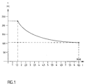
- FIG. 1 explains this prior art in a diagram which shows the tread depth t to 8.5 mm, a common tread depth for new passenger car tires, on the horizontal axis and the required braking distance from 120 km / h for a specific one on the vertical axis Water depth. While a full braking distance of 105 m is sufficient at full tread depth, a braking distance of 225 m is required at 1.6 mm tread depth, the minimum tread depth recently defined by law, which is more than double.
- the inventors come to the conclusion that many rear-end collisions on rain-drenched roads would be avoidable or at least would have been more mild if the increase in braking distance were at least smaller, preferably completely suppressed, over a wide range as the tread depth decreased. It is not only disturbing the long braking distance itself but - if several vehicles drive in a line in a row - also its different length from vehicle to vehicle, depending on the profile depth remaining there.
- the object is achieved by the characterizing features of claim 1, that is, in that the physical properties relevant for the braking distance on wet radially innermost layer of the tread which comes into contact with the road towards the end of the service life are larger than those for the braking distance Wet physical properties of the radially outermost layer that comes into contact with the road at the beginning of the service life of the tire.
- the physical properties mentioned here, which are relevant for the braking distance on wet are determined by the choice of material, i.e. the mixture recipe and the chemical structure of the mixture components, especially the polymer (s), the fillers and vulcanization aids.
- the most important physical property of a vulcanized rubber compound which is relevant for the braking distance on wet, is the hysteresis. Another essential characteristic is softness.
- the person skilled in the art knows, at least with sufficient knowledge of the friction partner road, which frequency and temperature ranges are particularly important.
- the braking distance can be significantly shortened with a small tread depth
- the acceptance of a small braking distance extension with full tread depth can be accepted - in each case compared to the prior art.
- the inventors have already separated from the known in their task, namely the exclusive consideration of the braking distance of the new tire and its possible shortening.
- the tread is expediently not only composed of two (as would already correspond to the solution according to the invention according to claim 1), but of several different layers in the depth region in which road contact is provided; as a result, the braking distance jump (see also FIG. 4) can be kept small when a layer interface enters the periphery; Admittedly, the number of shifts cannot be driven up arbitrarily in consideration of the production costs; a division into four layers seems to be a happy compromise between the different points of view.
- a further stabilization of the braking distance in wet conditions above the tread depth can be achieved in that the layer interfaces are inclined to the peripheral lines that result over the service life.
- the change from one mixture to the other does not occur spontaneously over the entire axial width, but initially only at the axial point where the next inner layer first comes to the periphery, after which the axial extent of the contact area portion of the next inner layer gradually increases.
- both means are basically interchangeable; however, the optimum seems to be a combination of both:
- the hysteresis of the innermost layer which should extend at least from 1.6 mm to 2.0 mm above the base of the profile groove, should preferably be at least 10% greater than at the periphery. The same applies preferably to the softness.
- FIG. 2 shows a pneumatic vehicle tire 1 in cross section.
- a carcass 4 - shown here in one layer - is wrapped, above which two belt plies 5 and 6 are located.
- base 7 which is a rubber layer which is known to have a very low hysteresis in order to keep the rolling resistance low.
- this layer has an insulation function against high-frequency vibrations, which should not act too much on the belt plies 5, 6 and carcass 4, which potentially act as resonance bodies.
- a so-called “cap” 8 is located radially outside the base 8. The features according to the invention are realized in this cap 8, as shown in FIG. 3 in detail. Cap 8 and base 7 are collectively referred to as treads according to the usual technical language.
- Figure 3 shows the cap 8 as a detail.
- the division of the cap 8 according to the invention into different, here four, layers 8a, 8b, 8c and 8d can be seen on this larger image scale - this figure is true to scale in the radial.
- These layers 8a to 8d are staggered in their hysteresis and softness in such a way that the coefficient of friction ⁇ increases from radially outside to radially inside when wet in comparison with conventional road surfaces.
- the retained characteristic is the low hysteresis in base 7.
- hysteresis differences from layer to layer in cap 8 should only be small, preferably about 8 %, there should be a sharp drop in hysteresis at the transition from the innermost cap layer 8d to the base 7, but at most a slight difference in stiffness to avoid excessive stress concentrations.
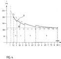
- FIG. 4 first shows a repetition in broken line 9 of the braking distance curve according to the prior art as shown in FIG. 1 and in full line 10 the braking distance curve of a tire 1 according to the invention.
- the radially outermost layer (8a in FIG. Tread depth t ranges from 8.5 mm to 5.1 mm
- the hysteresis i.e. the flexing work related to the deformation path
- the hysteresis i.e. the flexing work related to the deformation path
- the next innermost layer 8d the innermost layer of the cap 8, to which the area d in this diagram corresponds, consists of a particularly hysterical and soft rubber mixture, such as that used for applications in a tread, neither the cap 8 nor the base 7, according to the research of the Applicant has not been proposed so far.
- Such a rubber compound can be produced by vulcanizing the following rubber compound: SBR oil stretched (37.5% oil content) 137.5% aromatic oil 2.5% HS-HAF carbon black (BET 90 m2 / g) 80% sulfur 2.0% Zinc oxide 3.0% Stearic acid 2.0% wax 1.0% Antioxidant (paraphenylenediamine) 1.5% CBS (N-cyclohexyl-2-benzothiazole sulfenamide) 1.5% DPG (N, N'-diphenylguanidine) 0.2%
- all information means the proportion by weight of the respective component based on the total weight of all polymers, here only the styrene-butadiene copolymer (SBR). Because of this common reference point in the rubber processing industry, the total weight percent is over 100.
- SBR styrene-butadiene copolymer
- the oil premixed in the polymer is aromatic and has a Mooney viscosity ML4 of 55 at 100 ° C.
- the braking distance s shown in the diagram is shortened from 120 km / h.
- the minimum tread depth currently stipulated by law the braking distance s is only 200 m compared to 225 m for the reference tire.
- the braking distance difference between new condition and the most permitted, worn condition has shrunk from 120 m to 85 m. This significantly reduces the frequency and severity of rear-end collisions.
- the tread layer 8d extends down to a tread depth of 1.2 mm.
- the cap 8 of the tread is dimensioned so thin - in order to keep warming up and increasing the rolling resistance within limits - that the webs of the vulcanization form, which stamp the grooves in the still unprofiled blank, pierce the cap 8, so to speak, so that the base seen from the periphery with its very low hysteresis, which is known per se, does not begin below the profile groove base, as is known, but already starts at a profile depth of 1.2 mm.
- the invention brings an increase in vehicle safety in today's prevailing traffic situations, where accidents are caused not by the behavior of an individual vehicle but by the mismatched behavior of a collective of vehicles.
Abstract
Description
Die Erfindung bezieht sich auf einen Fahrzeugreifen mit Laufstreifen gemäß dem Oberbegriff des Anspruches 1. Die im Laufstreifen angeordneten - in der Serienfertigung üblicherweise während des Vulkanisierens in einer Form eingeprägten - Negative haben im wesentlichen die Aufgabe, bei Betrieb auf nassen Straßen Wasser aufzunehmen, damit die Bodenhaftung des Reifens so wenig wie möglich beeinträchtigt wird. Neben der Formgebung - wie Krümmungsverlauf und Schlankheitsverhältnis - hängt die erreichte Größe der gewünschten Wasserverdrängung maßgeblich vom Negativvolumen ab. Dieses wiederum ist das Integral über der Profiltiefe der Negativfläche bei Schnitt in Umfangsrichtung an jeder profiltiefenstelle in den Grenzen vom Profilrillengrund bis zur aktuellen Peripherie; kurzum das Negativvolumen nimmt über der Lebensdauer mit abnehmender Profiltiefe ab und die Bremswege nehmen entsprechend zu.The invention relates to a vehicle tire with treads according to the preamble of
Figur 1 erläutert diesen Stand der Technik in einem Diagramm, welches auf der waagerechten Achse die Profiltiefe t bis 8,5 mm, einer geläufigen Profiltiefe für PKW-Neureifen, zeigt und auf der senkrechten Achse den erforderlichen Bremsweg aus 120 km/h bei einer bestimmten Wassertiefe. Während bei voller Profiltiefe noch ein Bremsweg von 105 m ausreicht, ist bei 1,6 mm Profiltiefe, der vom Gesetzgeber kürzlich neu festgelegten Profilmindesttiefe, schon ein Bremsweg von 225 m erforderlich, also mehr als das doppelte.FIG. 1 explains this prior art in a diagram which shows the tread depth t to 8.5 mm, a common tread depth for new passenger car tires, on the horizontal axis and the required braking distance from 120 km / h for a specific one on the vertical axis Water depth. While a full braking distance of 105 m is sufficient at full tread depth, a braking distance of 225 m is required at 1.6 mm tread depth, the minimum tread depth recently defined by law, which is more than double.
Hiervon ausgehend gelangen die Erfinder zu der Einschätzung, daß viele Auffahrunfälle auf regennasser Straße vermeidlich wären oder zumindest glimpflicher verliefen, wenn der Bremsweganstieg über abnehmender Profiltiefe zumindest kleiner, vorzugsweise über einen weiten Bereich völlig unterdrückt wäre. Es stört nämlich nicht nur des Bremsweges große Länge an sich sondern - wenn mehrere Fahrzeuge in einer "Schlange" hintereinander herfahren - auch dessen verschiedene Länge von Fahrzeug zu Fahrzeug, je nach dort verbiebener Profilresttiefe.Based on this, the inventors come to the conclusion that many rear-end collisions on rain-drenched roads would be avoidable or at least would have been more mild if the increase in braking distance were at least smaller, preferably completely suppressed, over a wide range as the tread depth decreased. It is not only disturbing the long braking distance itself but - if several vehicles drive in a line in a row - also its different length from vehicle to vehicle, depending on the profile depth remaining there.
Dies sei anhand von Figur 1 an einem Beispiel erläutert:
Es fahre ein erstes Fahrzeug mit 120 km/h auf ein Hindernis zu und bemesse den Zeitpunkt seines Verzögerungsbeginns so, daß es eingedenk seiner neuen Reifen gerade noch vor dem Hindernis zum Stillstand komme. Ein nachfolgendes Fahrzeug mit weitestzulässig abgefahrenen Reifen könne das Hindernis nicht durch das voraus fahrende Fahrzeug hindurch sehen und halte zu diesem einen Abstand von weniger als 225m - 105m, also weniger als 120 m, ein. Selbst wenn die Reaktionszeit des hinterher fahrenden Fahrzeuges 0 wäre, wäre das Auffahren des hinteren Fahrzeuges auf das vordere unvermeidlich.This is explained using an example with reference to FIG. 1:
It drives a first vehicle at 120 km / h towards an obstacle and measures the time at which it begins to decelerate in such a way that its new tires come to a standstill just before the obstacle. A following vehicle with tires that are as far away as possible cannot see the obstacle through the vehicle in front and keep a distance of less than 225m - 105m, i.e. less than 120m. Even if the response time of the vehicle traveling behind were 0, the rear vehicle would inevitably collide with the vehicle in front.
Für den Fall, daß das erste Fahrzeug an sich hätte früher bremsen können, einen früheren Bremsbeginn mit entsprechend verringerte Maximalverzögerung also nur deshalb unterließ, weil es nach Verinnerlichung des eigenen guten Bremsvermögens keine Notwendigkeit dazu sah, hätte ein längerer Bremsweg dieses ersten Fahrzeuges das geschilderte Unfall-Szenario unwahrscheinlicher oder zumindest milder gemacht.In the event that the first vehicle in itself could have braked earlier, and therefore did not start earlier with a correspondingly reduced maximum deceleration only because it did not see any need to do so after internalizing its own braking ability, a longer braking distance of this first vehicle would have the described accident Scenario made less likely or at least milder.
Diese Überlegungen führten zu der originellen technischen Aufgabenstellung, neben der Länge des Bremsweges dessen Varianz über variierender Profiltiefe zu verringern.These considerations led to the original technical task of reducing the variance over varying tread depth in addition to the length of the braking distance.
Die Aufgabe wird erfindungsgemäß durch die kennzeichnenden Merkmale des Anspruches 1 gelöst, also dadurch, daß die für den Bremsweg auf Nässe relevanten physikalischen Eigenschaften der radial innersten, gegen Ende der Nutzungsdauer des Reifens in Fahrbahnkontakt tretenden Schicht des Laufstreifens größer sind als die für den Bremsweg auf Nässe relevanten physikalischen Eigenschaften der radial äußersten, zu Beginn der Nutzungsdauer des Reifens in Fahrbahnkontakt tretenden Schicht. Die hier angesprochenen, für den Bremsweg auf Nässe relevanten physikalischen Eigenschaften werden durch die Werkstoffwahl, also das Mischungsrezept und den chemischen Aufbau der Mischungsbestandteile, besonders des bzw. der Polymere, der Füllstoffe und Vulkanisationshilfen bestimmt.The object is achieved by the characterizing features of
Die nach derzeitigem Kenntnisstand wichtigste physikalische Eigenschaft einer vulkanisierten Kautschukmischung, die für den Bremsweg auf Nässe relevant ist, ist die Hysterese. Eine weitere wesentliche Eigenschaft ist die Weichheit. Dem Fachmann ist bekannt, zumindest bei hinreichender Kenntnis des Reibungspartners Fahrbahn, auf welche Frequenz- bzw. Temperaturbereiche es dabei besonders ankommt.According to the current state of knowledge, the most important physical property of a vulcanized rubber compound, which is relevant for the braking distance on wet, is the hysteresis. Another essential characteristic is softness. The person skilled in the art knows, at least with sufficient knowledge of the friction partner road, which frequency and temperature ranges are particularly important.
Bei erfindungsgemäßer Varianz der Hysteresis und/oder der Weichheit über der Radialen gibt es einen Konflikt zwischen den beiden Einzelzielen der Aufgabenstellung: Würde die äußerste Schicht des Laufstreifens und damit auch deren Hysterese und Weichheit, also die beiden den Reibbeiwert im wesentlichen determinierenden Parameter, so gewählt wie an einem Referenzreifen des Standes der Technik, sodaß dessen Bremsweg bei Nässe im Neuzustand unverändert bliebe, und würde erfindungsgemäß von Schicht zu Schicht nach innen gehend die Hysterese bei unveränderter Härte erhöht, so würde ein solcher Reifen neben einer verringerten Verschlechterung der Bremsleistung über der Nutzungsdauer eine Verschlechterung im Rollwiderstand zeigen.With the variance of the hysteresis and / or the softness over the radial according to the invention, there is a conflict between the two individual objectives of the task: Would the outermost layer of the tread and thus also its hysteresis and softness, i.e. the two parameters essentially determining the coefficient of friction, be chosen as on a reference tire of the prior art, so that its braking distance remains unchanged when wet when new, and if the hysteresis increased inward from layer to layer with unchanged hardness according to the invention, such a tire would, in addition to a reduced deterioration in braking performance over the service life show a deterioration in rolling resistance.
Denn die inneren Schichten mit ihrer hohen Hysteresis vergrößern ihren Anteil am Rollwiderstand. Abgesehen von einem erhöhten Treibstoffverbrauch führt dies auch zu einer größeren Polymeraufheizung und damit verringerter Alterungsbeständigkeit und Hochgeschwindigkeitsfestigkeit. Ein gewisser Ausgleich ist dadurch möglich, das gegenüber dem Stand der Technik nicht nur die Hysteresis der innersten noch in Fahrbahnkontakt geratenden Schicht erhöht wird, sondern auch die Hysteresis der äußersten Schicht gesenkt wird; damit aber müßte eine gewisse Verlängerung des Bremsweges des Reifens im Neuzustand hingenommen werden.Because the inner layers with their high hysteresis increase their share of rolling resistance. In addition to increased fuel consumption, this also leads to greater polymer heating and thus reduced resistance to aging and high speed. A certain compensation is possible by not only increasing the hysteresis of the innermost layer that is still in contact with the road, but also reducing the hysteresis of the outermost layer; however, this would have to mean a certain increase in the braking distance of the tire when new.
Gelingt eine deutliche Verkürzung des Bremsweges bei kleiner Profiltiefe, so kann die Hinnahme einer kleinen Bremswegverlängerung bei voller Profiltiefe - jeweils gegenüber dem Stand der Technik - hingenommen werden. Insofern haben sich die Erfinder schon bei ihrer Aufgabenstellung vom Bekannten, nämlich dem ausschließlichen Beachten des Bremsweges des Neureifen und dessen möglichster Verkürzung getrennt.If the braking distance can be significantly shortened with a small tread depth, the acceptance of a small braking distance extension with full tread depth can be accepted - in each case compared to the prior art. In this respect, the inventors have already separated from the known in their task, namely the exclusive consideration of the braking distance of the new tire and its possible shortening.
Zweckmäßigerweise wird der Laufstreifen in dem Tiefenbereich, in dem Fahrbahnkontakt vorgesehen ist, nicht nur aus zwei (wie es der erfindungsgemäßen Lösung nach Anspruch 1 bereits entsprechen würde), sondern aus mehreren verschiedenen Schichten zusammengesetzt; dadurch kann der Bremswegsprung (siehe auch Figur 4) bei Eintreten einer Schichtengrenzfläche in die Peripherie klein gehalten werden; freilich kann die Schichtenzahl mit Rücksicht auf die Produktionskosten nicht beliebig hoch getrieben werden; eine Untergliederung in vier Schichten scheint ein glücklicher Kompromiß zwischen den verschiedenen Gesichtspunkten zu sein.The tread is expediently not only composed of two (as would already correspond to the solution according to the invention according to claim 1), but of several different layers in the depth region in which road contact is provided; as a result, the braking distance jump (see also FIG. 4) can be kept small when a layer interface enters the periphery; Admittedly, the number of shifts cannot be driven up arbitrarily in consideration of the production costs; a division into four layers seems to be a happy compromise between the different points of view.
Eine noch weitergehende Verstetigung des Bremswegverlaufes bei Nässe über der Profiltiefe kann dadurch erreicht werden, daß die Schichtengrenzflächen schräg zu den sich über der Lebensdauer ergebenden Peripherielinien gestellt werden. Dadurch erfolgt der Wechsel von einer zur anderen Mischung nicht spontan über der ganzen axialen Breite sondern zunächst nur an der axialen Stelle, wo die nächstinnere Schicht zuerst an die Peripherie tritt, wonach die axiale Erstreckung des Kontaktflächenanteiles der nächstinneren Schicht allmählich zunimmt.A further stabilization of the braking distance in wet conditions above the tread depth can be achieved in that the layer interfaces are inclined to the peripheral lines that result over the service life. As a result, the change from one mixture to the other does not occur spontaneously over the entire axial width, but initially only at the axial point where the next inner layer first comes to the periphery, after which the axial extent of the contact area portion of the next inner layer gradually increases.
Neben einer Vergrößerung der Hysteresis nach radial innen hin bei konstanter Härte führt auch eine Vergrößerung der Weichheit nach radial innen hin bei konstanter Härte zu erhöhtem Reibungsbeiwert µ und genauso auch zu erhöhtem Walkwiderstand. Von daher sind beide Mittel grundsätzlich austauschbar; indessen scheint das Optimum in einer Kombination beider Mittel zu liegen:
Es empfiehlt sich eine Hysterese-Zunahme bei im wesentlichen konstanter Härte beim Übergang von der äußersten zur zweitäußersten Schicht, eine Weichheit-Zunahme bei im wesentlichen konstanter Hysteresis beim Übergang von der zweitinnersten zur innersten in Fahrbahnkontakt tretenden Schicht und eine entsprechend kleinere Varianz beider Einzelgrößen an jedem weiteren dazwischen liegenden Schichtübergang. Vorzugsweise sollte die Hysteresis der innersten Schicht, die sich zumindest von 1,6 mm bis 2,0 mm oberhalb des Profilrillengrundes erstrecken sollte, um mindestens 10 % größer sein als an der Peripherie. Entsprechendes gilt vorzugsweise für die Weichheit.In addition to an increase in radially inward hysteresis with constant hardness, an increase in softness inward radially with constant hardness leads to an increased coefficient of friction µ and also to increased flex resistance. Therefore, both means are basically interchangeable; however, the optimum seems to be a combination of both:
We recommend an increase in hysteresis with an essentially constant hardness during the transition from the outermost to the second outermost layer, an increase in softness with an essentially constant hysteresis in the transition from the second innermost to the innermost layer in contact with the road and a correspondingly smaller variance of both individual sizes on each another layer transition in between. The hysteresis of the innermost layer, which should extend at least from 1.6 mm to 2.0 mm above the base of the profile groove, should preferably be at least 10% greater than at the periphery. The same applies preferably to the softness.
Die Erfindung wird nachfolgend anhand der Figuren 2 bis 4 näher erläutert.The invention is explained in more detail below with reference to FIGS. 2 to 4.
Figur 2 zeigt einen Fahrzeugluftreifen 1 im Querschnitt. In an sich bekannter Weise ist um die beiden in Wülsten 3 angeordneten Wulstkerne 2 eine - hier einlagig gezeigte - Karkasse 4 herumgeschlungen, oberhalb der sich zwei Gürtellagen 5 und 6 befinden. Darauf befindet sich eine sogenannte "base" 7, das ist eine Kautschukschicht, die bekanntermaßen eine sehr geringe Hysteresis aufweist, um den Rollwiderstand klein zu halten. Neben einer gewissen Schutzfunktion gegenüber den darunter befindlichen Gürtellagen hat diese Schicht eine Isolationsfunktion gegenüber hochfrequenten Schwingungsanteilen, die nicht in zu großem Maße auf die potentiell als Resonanzkörper wirkenden Gürtellagen 5, 6 und Karkasse 4 einwirken soll. Radial außerhalb der base befindet sich eine sogenannte "cap" 8. In dieser cap 8 sind die erfindungsgemäßen Merkmale verwirklicht, wie in Figur 3 en détail gezeigt. Cap 8 und base 7 werden gemäß üblicher Fachsprache zusammenfassend als Laufstreifen bezeichnet.Figure 2 shows a
Figur 3 zeigt die cap 8 als Einzelheit. In diesem größeren Abbildungsmaßstab - diese Figur ist in der Radialen maßstabsgerecht - ist die erfindungsgemäße Unterteilung der cap 8 in verschiedene, hier vier, Schichten 8a, 8b, 8c und 8d zu erkennen. Diese Schichten 8a bis 8d sind in ihrer Hysterese und ihrer Weichheit so gestaffelt, daß der Reibungsbeiwert µ gegenüber üblichem Straßenbelag bei Nässe von radial außen nach radial innen hin zunimmt. Im Gegensatz zur Hysterese-Zunahme innerhalb der cap 8 beim Gang von außen nach innen steht das beibehaltene Merkmal, der geringen Hysterese in der base 7. Während die Hysterese-Differenzen von Schicht zu Schicht in der cap 8 nur klein sein sollen, vorzugsweise etwa 8 %, soll bei Übergang von der innersten cap-Schicht 8d zur base 7 ein schroffer Hysterese-Abfall vorliegen, aber allenfalls ein geringer Steifigkeitsunterschied zur Vermeidung zu großer Spannungskonzentrationen.Figure 3 shows the
Figur 4 zeigt zunächst eine Wiederholung in gestrichelter Linie 9 des Bremswegverlaufes nach dem Stand der Technik wie in Figur 1 gezeigt und in Volllinie 10 den Bremswegverlauf eines erfindungsgemäßen Reifens 1. In der radial äußersten Schicht (8a in Figur 3), die von einer Neu-Profiltiefe t von 8,5 mm bis 5,1 mm reicht, ist zur Vermeidung zu großer Reifenaufheizung die Hysteresis, also die auf den Verformungsweg bezogene Walkarbeit, kleiner gehalten als nach dem Stand der Technik üblich. Entsprechend wird im Bereich a ein geringer Abfall des Reibungsbeiwertes und demzufolge ein Anstieg des Bremsweges s auf Nässe gegenüber dem Referenzreifen hingenommen; der Bremsweg des Neureifens auf Nässe ist von 105 m auf 115 m angestiegen.FIG. 4 first shows a repetition in broken line 9 of the braking distance curve according to the prior art as shown in FIG. 1 and in
In der nächstinneren Schicht (8b in Figur 3), zu der der Bereich b des Diagramms gehört, ist die gleiche Kautschukmischung verwendet wie beim Referenzreifen. Dementsprechend decken sich in diesem Bereich die Bremswegverläufe 9 und 10.In the next inner layer (8b in FIG. 3), to which area b of the diagram belongs, the same rubber mixture is used as for the reference tire. Accordingly, the
In dem daran anschließenden nächstinneren Bereich c des Bremswegverlaufes 10, der von der Profiltiefe 3,3 mm bis 2,1 mm - der von der Anmelderin für sinnvoll gehaltenen Profilmindesttiefe - reicht, ist eine dämpfungsreichere Kautschukmischung verwendet. Unter Inkaufnahme einer in diesem Bereich vermehrt anfallenden Wärmeleistung wird dadurch ein großerer Reibungsbeiwert µ und damit ein kürzerer Bremsweg s auf Nässe als mit dem Referenzreifen erreicht.In the adjoining next inner area c of the
Die nächstinnerste Schicht 8d, die innerste Schicht der cap 8, der der Bereich d in diesem Diagramm entspricht, besteht aus einer besonders hysteresereichen und weichen Gummimischung, wie sie für Anwendungen in einem Laufstreifen, weder der cap 8 noch der base 7, nach Recherche der Anmelderin bislang nicht vorgeschlagen wurde. Eine solche Gummimischung kann durch Vulkanisation folgender Kautschukmischung erzeugt werden:
In dieser Rezeptur bedeuten alle Angaben den Gewichtsanteil der jeweiligen Komponente bezogen auf das Gesamtgewicht aller Polymere, hier also nur das Styrol-Butadien-Copolymer (SBR). Wegen diesem in der kautschukverarbeitenden Industrie üblichen Bezugspunkt liegt die Gesamtsumme der Gewichtsprozente über 100. Das in das Polymer vorgemischte Öl ist aromatisch und hat bei 100°C eine Mooney-Viskosität ML4 von 55.In this recipe, all information means the proportion by weight of the respective component based on the total weight of all polymers, here only the styrene-butadiene copolymer (SBR). Because of this common reference point in the rubber processing industry, the total weight percent is over 100. The oil premixed in the polymer is aromatic and has a Mooney viscosity ML4 of 55 at 100 ° C.
Entsprechend der großen Hysterese und kleinen Steifigkeit dieser Gummimischung wird ein außergewöhnlich großer Reibungsbeiwert auf Nässe erreicht, der eine besonders große Bremsverzögerung zuläßt. Dementsprechend wird der im Diagramm gezeigte Bremsweg s aus 120 km/h verkürzt. Bei 1,6 mm Profiltiefe, der derzeitig vom Gesetzgeber festgeschriebenen Mindestprofiltiefe, beträgt der Bremsweg s nur noch 200 m gegenüber 225 m beim Referenzreifen. Zusammen mit der geringen Bremswegverlängerung im Neuzustand ist die Bremswegdifferenz zwischen Neuzustand und weitesterlaubtem abgefahrenen Zustand von 120 m auf 85 m geschrumpft. Häufigkeit und Schwere von Auffahrunfällen werden dadurch deutlich gesenkt.In accordance with the large hysteresis and small stiffness of this rubber compound, an extraordinarily large coefficient of friction on wet is achieved, which allows a particularly large braking deceleration. Accordingly, the braking distance s shown in the diagram is shortened from 120 km / h. With a tread depth of 1.6 mm, the minimum tread depth currently stipulated by law, the braking distance s is only 200 m compared to 225 m for the reference tire. Together with the small braking distance extension when new, the braking distance difference between new condition and the most permitted, worn condition has shrunk from 120 m to 85 m. This significantly reduces the frequency and severity of rear-end collisions.
Da Reifen nicht immer ganz gleichmäßig abreiben und vor allem weil leider immer wieder einige Autofahrer selbst die gesetzliche Mindestprofiltiefe von 1,6 mm nicht einhalten und damit andere Verkehrsteilnehmer gefährden, reicht die Laufstreifenschicht 8d bis auf eine Profiltiefe von 1,2 mm herunter.Since tires do not always rub off evenly and, above all, because unfortunately some drivers do not always comply with the legal minimum tread depth of 1.6 mm and thus endanger other road users, the
Die cap 8 des Laufstreifens ist so dünn bemessen - um Aufwärmung und Rollwiderstandserhöhung in Grenzen zu halten -, daß die Stege der Vulkanisationsform, die die Nuten in den noch unprofilierten Rohling einprägen, die cap 8 gewissermaßen durchstechen, sodaß von der Peripherie her gesehen die base mit ihrer an sich bekannten sehr geringen Hysterese nicht erst wie bekannt unterhalb des Profilrillengrundes beginnt sondern bereits bei 1,2 mm Profiltiefe.The
Die Erfindung bringt eine Erhöhung der Fahrzeugsicherheit in den heutzutage überwiegend vorliegenden Verkehrssituationen, wo Unfälle nicht durch das Verhalten eines individuellen Fahrzeuges sondern durch nicht zueinander passendes Verhalten eines Kollektives von Fahrzeugen verursacht werden.The invention brings an increase in vehicle safety in today's prevailing traffic situations, where accidents are caused not by the behavior of an individual vehicle but by the mismatched behavior of a collective of vehicles.
Claims (7)
dadurch gekennzeichnet,
daß die für den Bremsweg auf Nässe relevanten physikalischen Eigenschaften der radial innersten, gegen Ende der Nutzungsdauer des Fahrzeugreifens (1) in Fahrbahnkontakt tretenden Schicht (8d) des Laufstreifens (7, 8) größer sind als die für den Bremsweg auf Nässe relevanten physikalischen Eigenschaften der radial äußersten, zu Beginn der Nutzungsdauer des Fahrzeugreifens (1) in Fahrbahnkontakt tretenden Schicht (8a) des Laufstreifens (7, 8).Vehicle tire (1) with a tread (7, 8) arranged on its radially outer side, which is subdivided into at least two layers (8a, 8b, 8c, 8d, 7), these layers being relevant with regard to their braking distance in the wet distinguish physical properties,
characterized,
that the physical properties of the radially innermost, radially innermost braking distance towards the end of the service life of the vehicle tire (1) coming into contact with the road (8d) of the tread (7, 8) are greater than the physical properties of the braking distance on wet radially outermost layer (8a) of the tread (7, 8) coming into contact with the road at the beginning of the service life of the vehicle tire (1).
dadurch gekennzeichnet, daß die cap (8) in mindestens zwei Schichten (8a, 8d) unterteilt ist, wobei entsprechend dem Kennzeichen des Anspruches 1 die Hysteresis der radial innersten, zuletzt in Fahrbahnkontakt tretenden Schicht (8d) der cap (8) größer ist als die Hysteresis der radial äußersten Schicht (8a) der cap (8).Vehicle tire (1) according to claim 1, wherein the tread (7, 8) is divided into a cap (8) and a base (7) in a manner known per se, the base (7) being low in hysteresis in a manner known per se,
characterized in that the cap (8) is subdivided into at least two layers (8a, 8d), the hysteresis of the radially innermost layer (8d) which last comes into contact with the road surface of the cap (8) being greater than that according to the characterizing part of claim 1 the hysteresis of the radially outermost layer (8a) of the cap (8).
Applications Claiming Priority (2)
| Application Number | Priority Date | Filing Date | Title |
|---|---|---|---|
| DE4235419 | 1992-10-21 | ||
| DE19924235419 DE4235419A1 (en) | 1992-10-21 | 1992-10-21 | Vehicle tires with treads |
Publications (1)
| Publication Number | Publication Date |
|---|---|
| EP0594045A1 true EP0594045A1 (en) | 1994-04-27 |
Family
ID=6470938
Family Applications (1)
| Application Number | Title | Priority Date | Filing Date |
|---|---|---|---|
| EP93116535A Withdrawn EP0594045A1 (en) | 1992-10-21 | 1993-10-13 | Vehicle tyre tread |
Country Status (2)
| Country | Link |
|---|---|
| EP (1) | EP0594045A1 (en) |
| DE (1) | DE4235419A1 (en) |
Cited By (6)
| Publication number | Priority date | Publication date | Assignee | Title |
|---|---|---|---|---|
| EP0715974A1 (en) * | 1994-11-07 | 1996-06-12 | The Goodyear Tire & Rubber Company | Triplex tread |
| EP1398182A2 (en) * | 2002-09-13 | 2004-03-17 | The Goodyear Tire & Rubber Company | tire with a multi-layered tread |
| EP2457743A1 (en) * | 2010-11-30 | 2012-05-30 | The Goodyear Tire & Rubber Company | Pneumatic tire |
| FR2999118A1 (en) * | 2012-12-10 | 2014-06-13 | Michelin & Cie | PNEUMATIC COMPRISING A TREAD TAPE CONSISTING OF SEVERAL ELASTOMERIC MIXTURES |
| CN105121183A (en) * | 2013-04-24 | 2015-12-02 | 株式会社普利司通 | Pneumatic tire |
| EP2855171A4 (en) * | 2012-05-25 | 2016-01-13 | Michelin & Cie | Method and tire for improved uniformity and endurance of aggressive tread designs using layering technique |
Families Citing this family (2)
| Publication number | Priority date | Publication date | Assignee | Title |
|---|---|---|---|---|
| DE19731525A1 (en) * | 1997-07-23 | 1998-07-09 | Continental Ag | All year round commercial vehicle tyre eliminating tyre changes between summer and winter |
| DE102009035294A1 (en) * | 2009-07-30 | 2011-02-10 | Bayerische Motoren Werke Aktiengesellschaft | Motor vehicle tire i.e. pneumatic tire, has running surface made of rubber mixture, where structure of tire is arranged such that physical tire characteristics are provided with respect to winter tire |
Citations (6)
| Publication number | Priority date | Publication date | Assignee | Title |
|---|---|---|---|---|
| DE1901448A1 (en) * | 1968-01-12 | 1969-08-28 | Dunlop Co Ltd | tire |
| US4381810A (en) * | 1981-05-22 | 1983-05-03 | The Goodyear Tire & Rubber Company | Tire with dual tread compound |
| EP0097787A2 (en) * | 1982-06-26 | 1984-01-11 | Continental Aktiengesellschaft | Pneumatic tyre |
| EP0098353A2 (en) * | 1982-06-26 | 1984-01-18 | Continental Aktiengesellschaft | Pneumatic tyre for winter use |
| EP0104133A2 (en) * | 1982-09-17 | 1984-03-28 | The Goodyear Tire & Rubber Company | Composite tread compounds for improved traction and rolling resistance |
| EP0105822A2 (en) * | 1982-06-09 | 1984-04-18 | The Goodyear Tire & Rubber Company | Tread |
-
1992
- 1992-10-21 DE DE19924235419 patent/DE4235419A1/en not_active Withdrawn
-
1993
- 1993-10-13 EP EP93116535A patent/EP0594045A1/en not_active Withdrawn
Patent Citations (6)
| Publication number | Priority date | Publication date | Assignee | Title |
|---|---|---|---|---|
| DE1901448A1 (en) * | 1968-01-12 | 1969-08-28 | Dunlop Co Ltd | tire |
| US4381810A (en) * | 1981-05-22 | 1983-05-03 | The Goodyear Tire & Rubber Company | Tire with dual tread compound |
| EP0105822A2 (en) * | 1982-06-09 | 1984-04-18 | The Goodyear Tire & Rubber Company | Tread |
| EP0097787A2 (en) * | 1982-06-26 | 1984-01-11 | Continental Aktiengesellschaft | Pneumatic tyre |
| EP0098353A2 (en) * | 1982-06-26 | 1984-01-18 | Continental Aktiengesellschaft | Pneumatic tyre for winter use |
| EP0104133A2 (en) * | 1982-09-17 | 1984-03-28 | The Goodyear Tire & Rubber Company | Composite tread compounds for improved traction and rolling resistance |
Cited By (13)
| Publication number | Priority date | Publication date | Assignee | Title |
|---|---|---|---|---|
| EP0715974A1 (en) * | 1994-11-07 | 1996-06-12 | The Goodyear Tire & Rubber Company | Triplex tread |
| EP1398182A2 (en) * | 2002-09-13 | 2004-03-17 | The Goodyear Tire & Rubber Company | tire with a multi-layered tread |
| EP1398182A3 (en) * | 2002-09-13 | 2004-11-17 | The Goodyear Tire & Rubber Company | tire with a multi-layered tread |
| US6959743B2 (en) | 2002-09-13 | 2005-11-01 | The Goodyear Tire & Rubber Company | Tire with silica-rich tread cap layer and carbon black-rich supporting transition zone of intermediate and base layers |
| US8844595B2 (en) | 2010-11-30 | 2014-09-30 | The Goodyear Tire & Rubber Company | Pneumatic tire with tread including tread base layer and tread blocks having two different rubber layers |
| EP2457743A1 (en) * | 2010-11-30 | 2012-05-30 | The Goodyear Tire & Rubber Company | Pneumatic tire |
| US20120132331A1 (en) * | 2010-11-30 | 2012-05-31 | The Goodyear Tire & Rubber Cmpany | Pneumatic tire |
| EP2855171A4 (en) * | 2012-05-25 | 2016-01-13 | Michelin & Cie | Method and tire for improved uniformity and endurance of aggressive tread designs using layering technique |
| FR2999118A1 (en) * | 2012-12-10 | 2014-06-13 | Michelin & Cie | PNEUMATIC COMPRISING A TREAD TAPE CONSISTING OF SEVERAL ELASTOMERIC MIXTURES |
| WO2014090620A1 (en) * | 2012-12-10 | 2014-06-19 | Compagnie Generale Des Etablissements Michelin | Tyre comprising a tread made up of several elastomeric compounds |
| US10000091B2 (en) | 2012-12-10 | 2018-06-19 | Compagnie Generale Des Etablissements Michelin | Tire comprising a tread made up of several elastomeric compounds |
| CN105121183A (en) * | 2013-04-24 | 2015-12-02 | 株式会社普利司通 | Pneumatic tire |
| US20160075183A1 (en) * | 2013-04-24 | 2016-03-17 | Bridgestone Corporation | Pneumatic tire |
Also Published As
| Publication number | Publication date |
|---|---|
| DE4235419A1 (en) | 1994-04-28 |
Similar Documents
| Publication | Publication Date | Title |
|---|---|---|
| EP0950506B1 (en) | Process for the manufacture of a vehicle tyre | |
| DE60320324T2 (en) | TIRES FOR VEHICLES | |
| EP0798142B1 (en) | Vehicle tyre | |
| DE8035189U1 (en) | WHEEL RIM | |
| EP0434967A2 (en) | Tread pattern for vehicle tires | |
| DE2331530A1 (en) | SAFETY TIRES | |
| DE102008044213A1 (en) | tire | |
| DE102005030566B4 (en) | Pneumatic tire with incisions extending in tire width and formed on a tread | |
| DE69729248T2 (en) | Tires with high-transverse curvature, in particular for rear wheels of motor vehicles | |
| EP1308319A1 (en) | Pneumatic tire | |
| DE102019126482A1 (en) | Pneumatic tire | |
| DE2941852A1 (en) | TIRE TIRES IN RADIAL DESIGN FOR HEAVY VEHICLES | |
| EP0838353B1 (en) | Vehicle tyre | |
| DE102006007762A1 (en) | tire | |
| EP0594045A1 (en) | Vehicle tyre tread | |
| DE4022615A1 (en) | VEHICLE TIRE WITH CROSS-GROOVE | |
| EP3653360A1 (en) | Preform device and method for producing a vehicle tyre comprising at least two rubber components | |
| EP2138330A1 (en) | Pneumatic tyres for a vehicle | |
| DE102017126830B4 (en) | tire | |
| DE60030763T2 (en) | TIRES FOR HIGH PERFORMANCE CARS | |
| DE102017125940A1 (en) | tire | |
| EP1086832A2 (en) | Vehicle pneumatic tyre | |
| DE102006002050B4 (en) | tire | |
| DE102008055498A1 (en) | Pneumatic tire for utility vehicle, has tread including peripheral grooves provided in circumferential direction, where one of grooves has depth that is preset percent greater than depth of one of remaining grooves | |
| EP2977233B1 (en) | Pneumatic tyre for a vehicle |
Legal Events
| Date | Code | Title | Description |
|---|---|---|---|
| PUAI | Public reference made under article 153(3) epc to a published international application that has entered the european phase |
Free format text: ORIGINAL CODE: 0009012 |
|
| AK | Designated contracting states |
Kind code of ref document: A1 Designated state(s): DE FR GB IT |
|
| STAA | Information on the status of an ep patent application or granted ep patent |
Free format text: STATUS: THE APPLICATION IS DEEMED TO BE WITHDRAWN |
|
| 18D | Application deemed to be withdrawn |
Effective date: 19941028 |