EP0593899A1 - Saw wire rotating device - Google Patents
Saw wire rotating device Download PDFInfo
- Publication number
- EP0593899A1 EP0593899A1 EP93114729A EP93114729A EP0593899A1 EP 0593899 A1 EP0593899 A1 EP 0593899A1 EP 93114729 A EP93114729 A EP 93114729A EP 93114729 A EP93114729 A EP 93114729A EP 0593899 A1 EP0593899 A1 EP 0593899A1
- Authority
- EP
- European Patent Office
- Prior art keywords
- rope
- wire
- saw
- roller
- rotating roller
- Prior art date
- Legal status (The legal status is an assumption and is not a legal conclusion. Google has not performed a legal analysis and makes no representation as to the accuracy of the status listed.)
- Granted
Links
Images

Classifications
-
- B—PERFORMING OPERATIONS; TRANSPORTING
- B23—MACHINE TOOLS; METAL-WORKING NOT OTHERWISE PROVIDED FOR
- B23D—PLANING; SLOTTING; SHEARING; BROACHING; SAWING; FILING; SCRAPING; LIKE OPERATIONS FOR WORKING METAL BY REMOVING MATERIAL, NOT OTHERWISE PROVIDED FOR
- B23D57/00—Sawing machines or sawing devices not covered by one of the preceding groups B23D45/00 - B23D55/00
- B23D57/003—Sawing machines or sawing devices working with saw wires, characterised only by constructional features of particular parts
- B23D57/0053—Sawing machines or sawing devices working with saw wires, characterised only by constructional features of particular parts of drives for saw wires; of wheel mountings; of wheels
Definitions
- the invention relates to a device on wire saws for generating a constant and uniform rotational movement of the saw rope during the cut.
- the saw cable consists of a rope braided from several metal wires with attached cutting beads, which contain high-performance cutting material such as diamond and / or cubic boron nitride in a preferably metallic bond.
- high-performance cutting material such as diamond and / or cubic boron nitride in a preferably metallic bond.
- the saw rope twisting device was developed, which causes the rope to inevitably turn the rope during the sawing process, which ensures circular and concentric bead wear.
- the object of the invention is the rope rotating device described. It generates the described inevitable rotational movement of the saw cable safely and reliably in all wire saw applications.
- At least one steplessly profiled rope rotating roller with at least one rope entry area and a rope exit area which is comparatively smaller in diameter is provided.
- the basic principle of the rope rotating device is based on a preferably conically shaped roller (1) with a rubber or plastic covering. If a saw cable (2) is now fed onto the larger diameter of the conical roller profile, it will try on the roller (1) in the further course, due to the tensile force in the saw cable, to the smaller diameter of the roller by the amount (s) in Fig 4 to migrate. Since the friction between the diamond pearls and the support on the reel is very large, the rope is caused to move in the form of rolling movements and not by slipping. The rotary movement is thus generated and must be passed on to the remaining part of the rope via the elastic torsional resistance of the rope. This rotary movement is effectively passed on if the rope was pre-twisted with approx. 2 revolutions per linear meter of rope before use.
- the drive wheel (1 ') according to FIG. 2 can also be designed as a rope rotating roller, which is particularly advantageous for short rope lengths.
- the wrap angle ⁇ according to FIG. 3 can start from very small angles of approximately 30 ° to the special case of 360 ° corresponding to a full wrap be.
- constructive measures must be taken to ensure that the rope parts entering and leaving the rope rotating roller do not touch each other.
- High wear is to be expected when touching the two rope parts because the relative speed at the point of contact is about 3 (m / s) due to the frequently used cutting speed of 21 (m / s), as determined in the calculation example in Table 1 for the practical application data has been.
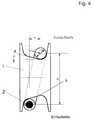
- the cone angle ⁇ in FIG. 4 only influences the force component F r with which the rope is forced to roll, but not the frequency of rotation of the rope about its axis.
- roller profiles modified according to the invention are conceivable, as exemplified in FIG. 5.
- the basic principle according to the invention of the unwinding of the rope in the course of the path covered in the wrap angle ⁇ remains largely unaffected by the embodiment of the rope running profile.
- a basic distinction must be made between one-way and two-way profiles.
- the rope running profile is preferably carried out symmetrically.
- the distance q between the rope inlet and the rope outlet on the rope rotating roller essentially determines the frequency of rotation of the rope in accordance with the calculation of the turning effect in the following calculation example. As the tests showed, a set distance q of 2-4 mm is sufficient for a reliable rope turning effect. Significantly higher q values generated harmful vibrations in the rope, so they should be avoided.
- the rope with the ⁇ d is displaced by a distance q when it rotates around the rope rotating roller (1) (1 ') and must therefore roll the distance s down the cone.
- s q / cos ⁇
- the length of the saw rope (2) located on the cone (4) is determined by the diameter D of the rope rotating roller (1) and the wrap angle ⁇ .
- the rope can be run in by connecting a guide roller (3) at any distance (e), preferably approx. 1 to 2 times the diameter of the rope rotating roller (1).
- the axis of this guide roller (3) can be at an entry angle ( ⁇ ) to the rope rotating roller (1) to enable a gentle rope run. It is advantageous to use a commercially available self-adjusting swivel castor.
- FIGS. 1 and 3 represents a possible embodiment of the invention of the rope turning device.
- additions with additional guide rollers in the rope inlet and rope outlet are conceivable, for example, for damping rope vibrations with long rope lengths, without the same effect according to the invention of the actual rope turning device influence.
- an inverted arrangement of the rope rotating roller (1) and the guide roller (3) with respect to the direction of the rope cutting has no restrictive effect on the aim of the invention, since in the opposite direction of the rope cutting only the direction of rotation the rope around its axis is also reversed, and otherwise no effect on the constant rotation according to the invention was found.
Landscapes
- Engineering & Computer Science (AREA)
- Mechanical Engineering (AREA)
- Processing Of Stones Or Stones Resemblance Materials (AREA)
- Lift-Guide Devices, And Elevator Ropes And Cables (AREA)
- Ropes Or Cables (AREA)
Abstract
Description
Die Erfindung bezieht sich auf eine Vorrichtung an Seilsägemaschinen zur Erzeugung einer ständigen und gleichmäßigen Drehbewegung des Sägeseils während des Schnittes.The invention relates to a device on wire saws for generating a constant and uniform rotational movement of the saw rope during the cut.
Das Sägeseil besteht aus einem aus mehreren Metalldrähten geflochtenen Seil mit daran befestigten Schneidperlen, die Hochleistungsschneidstoff wie Diamant und / oder kubisches Bornitrid in einer vorzugsweise metallischen Bindung enthalten. Beim Einsatz in stationären oder mobilen Seilsägemaschinen werden die Seilenden des Sägeseils mit einem Verschluß zu einer geschlossenen Scheilschleife verbunden.The saw cable consists of a rope braided from several metal wires with attached cutting beads, which contain high-performance cutting material such as diamond and / or cubic boron nitride in a preferably metallic bond. When used in stationary or mobile rope saws, the rope ends of the saw rope are connected with a lock to form a closed wedge loop.
Das Schneiden mit Drahtseilen ist ein althergebrachtes Verfahren zur Steinbearbeitung. Dabei wurde dem Spülwasser ein Schleifmittel zugemengt, welches die eigentliche Zerspanungsarbeit leistete.Cutting with wire ropes is an ancient method of stone processing. An abrasive was added to the rinsing water, which did the actual machining work.
Ein bedeutender Schritt in der Entwicklungsgeschichte der Seilsägetechnik ist die Einführung von diamantbesetzten Seilen wie die US-PS 4735 188 und die EP 0090 274 B1 zeigen, wobei die Diamantpartikeln zunächst auf der Mantelfläche von Hülsen galvanisch eingenickelt und diese "Perlen" anschließend auf ein Drahtseil aufgefädelt werden. Zwischen den einzelnen Perlen befinden sich dabei Federn als Abstandshalter, ca. hinter jeder 5. Perle gibt es einen Klemmring, welcher mit dem Drahtseil verpreßt wird und damit das Verschieben der Perlen auf dem Seil unterbindet. Bei dieser Variante eines Diamantsägeseiles können sich die Perlen frei drehen und deshalb kann der einschichtige Diamantbelag auch gut ausgenützt werden. Derartige Seile eignen sich jedoch nur für die Bearbeitung von weichen Materialien wie z.B. Marmor.An important step in the history of the development of wire saw technology is the introduction of diamond-coated ropes such as US Pat. No. 4,735,188 and EP 0090 274 B1, the diamond particles first being galvanically wrapped onto the outer surface of sleeves and these "beads" then being threaded onto a wire rope will. Between the individual pearls there are springs as spacers, approx. Behind every fifth pearl there is a clamping ring which is pressed with the wire rope and thus prevents the pearls from being shifted on the rope. With this variant of a diamond saw rope, the pearls can rotate freely and therefore the single-layer diamond coating can also be used well. However, such ropes are only suitable for processing soft materials such as marble.
Für erschwerte Bearbeitungsbedingungen wie z.B. Granit oder Beton wurde zunächst der gleiche Grundaufbau verwendet, statt der einschichtigen galvanischen Beläge wurden nun jedoch mehrschichtig gesinterte Beläge verwendet.For difficult machining conditions such as The same basic structure was initially used for granite or concrete, but instead of single-layer galvanic coverings, multilayer sintered coverings were used.
Sehr rasch stellte man jedoch fest, daß der beim Schneiden anfallende abrasive Schneidschlamm, welcher ungehindert an das Stahlseil herantreten kann, bei diesem Aufbau zu einer vorzeitigen Zerstörung des Stahlseiles führt. Es kommt daher beim praktischen Einsatz derartiger Seile sehr häufig zu Seilbrüchen, was die Wirtschaftlichkeit der Diamantseilsägetechnik bis dato erheblich einschränkte.Very quickly, however, it was found that the abrasive cutting sludge which accumulates during the cutting and which can approach the steel cable unhindered leads to a premature destruction of the steel cable with this construction. Therefore, when such ropes are used in practice, rope breaks occur very frequently, which has hitherto considerably restricted the economy of diamond wire saw technology.
Dieser Mangel führte zur nächsten Generation von Diamantsägeseilen mit den mit Kunststoff oder Gummi befestigten Seilperlen, wobei das Befestigungsmaterial auch gleichzeitig eine Schutzfunktion für das Trägerseil übernimmt entsprechend EP 0160 625 A2, EP 0306 952 A1, EP 0317 965 A2, US-PS-3 884 212 und IT Pat-Nr. 573635. An so gefertigten Sägeseilen können sich die einzelnen Perlen jedoch nicht mehr drehen, was besonders bei nachfolgend genannten Bedingungen zu einem unrunden Verschleiß der Diamantperlen und damit zu einer schlechten Wirtschaftlichkeit führt:
- · bei besonders kurzen Seilsägen (unter 5 m)
- · bei stationären Blocksäge- und Formschnittmaschinen (Seil wird nie verdreht)
- · bei extrem kurzen Kontaktlängen zwischen Seilsäge und Werkstück
- · bei Endlosseilen (keine Möglichkeit zum Verdrehen)
- · bei hoher Seilvorspannung
- · bei hohen Stahlarmierungsanteilen im Werkstück (Bau)
Für alle Seile, welche mit Seilverschlüssen ausgestattet sind, sind Handhabungsdetails bekannt, um die gleichmäßige Abnützung der Schneidperlen anzustreben. Dabei wird das regelmäßige Öffnen und Schließen des Seilverschlusses und damit das Stillsetzen der Sägeanlage erforderlich. Im Anlagenstillstand muß das Sägeseil händisch eingedreht, wieder geschlossen und neu durch Maschine und Werkstück geführt werden. Eine solche diskontinuierliche Arbeitsweise ist teuer und nicht in allen Anwendungsfällen anwendbar bzw. wird die Anwendungsgrenze des Seilsägeverfahrens unnötig eingeschränkt.This defect led to the next generation of diamond saw ropes with the rope beads fastened with plastic or rubber, the fastening material also simultaneously taking on a protective function for the carrier rope in accordance with EP 0160 625 A2, EP 0306 952 A1, EP 0317 965 A2, US Pat. No. 3,884 212 and IT Pat No. 573635. However, the individual beads can no longer turn on saw ropes made in this way, which leads to non-circular wear of the diamond beads and thus to poor economy, especially under the conditions mentioned below:
- With particularly short wire saws (less than 5 m)
- · With stationary block saws and shape cutting machines (rope is never twisted)
- · With extremely short contact lengths between wire saw and workpiece
- With endless ropes (no possibility of twisting)
- · With high rope tension
- · With high steel reinforcement in the workpiece (construction)
Handling details are known for all ropes which are equipped with rope closures in order to strive for even wear of the cutting beads. This requires regular opening and closing of the rope lock and thus stopping the saw system. When the system is at a standstill, the saw cable must be screwed in by hand, closed again and then reused by machine and workpiece are guided. Such a discontinuous method of operation is expensive and cannot be used in all applications, or the application limit of the wire saw method is unnecessarily restricted.
Zur generellen Lösung dieses Problems wurde die erfindungsgemäße Sägeseildrehvorrichtung entwickelt, welches das Seil während des Sägeprozesses zu einer zwangsläufigen Seildrehbewegung veranlaßt, welche eine kreisrunde und konzentrische Perlenabnützung sicherstellt.To generally solve this problem, the saw rope twisting device according to the invention was developed, which causes the rope to inevitably turn the rope during the sawing process, which ensures circular and concentric bead wear.
Der Gegenstand der Erfindung ist die beschriebene Seildrehvorrichtung. Sie erzeugt die beschriebene zwangsläufige Drehbewegung des Sägeseils bei allen Seilsägeanwendungen sicher und zuverlässig.The object of the invention is the rope rotating device described. It generates the described inevitable rotational movement of the saw cable safely and reliably in all wire saw applications.
Gemäß der Erfindung ist bei einer eingangs genannten Vorrichtung wenigstens eine stufenlos profilierte Seildrehrolle mit wenigstens einem Seileinlaufbereich und einem im Durchmesser vergleichsweise kleineren Seilauslaufbereich vorgesehen.According to the invention, in a device mentioned at the beginning, at least one steplessly profiled rope rotating roller with at least one rope entry area and a rope exit area which is comparatively smaller in diameter is provided.
Nachfolgend wird die Erfindung unter Bezugnahme auf die beigefügten Zeichnungen weiter erläutert:
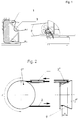
- Fig. 1 zeigt ein Ausführungsbeispiel einer Sägeseildrehvorrichtung, bei der das Sägeseil von einem separaten Antriebsaggregat angetrieben wird;
Die Seildrehrolle (1) ist unmittelbar vor dem Eintritt in den Werkstoff angeordnet, wobei eine bereits durchgeführte Drehung einzelner Perlen an einem Sägeseil (2) beim Eintritt in das zu bearbeitende Material über die Reibung fixiert wird. Die Seildrehrolle (1) besitzt eine Gummi- oder Kunststoffauflage, und es ist eine Führungsrolle (3) vorgesehen, deren Anordnung gemäß der Seildrehrolle (1) in Fig. 3 näher gezeigt ist. - Fig. 2 zeigt eine schematische Darstellung im Bereich einer als Seilantrieb wirkenden Seildrehrolle. Bei dem Ausführungsbeispiel gemäß Fig. 2 beträgt der Umschlingungswinkel ρ 180°, und die Führungsrolle (3') ist normal zu Seildrehrolle (1') angeordnet.
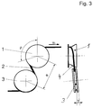
- Fig. 3 zeigt eine schematische Darstellung von Seildrehrolle (1) und Führungsrolle (3) zur Erläuterung des Umschlingungswinkel (ρ), des Rollenabstands (d) und des Einlaufwinkels (γ). Bei der Darstellung gemäß Fig. 3 beträgt der Umschlingungswinkel ρ des Sägeseils (2) um die Seildrehrolle (1) 106°, der Rollenabstand e zwischen Seildrehrolle (1) und Führungsrolle e 1,3xD und der Einlaufwinkel γ 4,5°. (D) ist, wie aus Fig. 4 ersichtlich, der wirksame Durchmesser von Seilmitte zu Seilmitte zwischen Einlauf- und Auslaufseite, bezogen auf die Drehachse der Seildrehrolle (1). In Fog. 3 ist der kurvenförmige Verlauf des Sägeseils (2) während des seitlichen Abrollens zwischen Seileinlauf- und Seilauslaufbereich der Seildrehrolle (1) gut sichtbar.
- Fig. 4 zeigt schematisch einen Schnitt durch eine Seildrehrolle (1) zur Erläuterung der Sägeseilanlageverhältnisse mit Einlaufseite unten und Auslaufseite oben, wobei ein Umschlingungswinkel ρ = 180° und ein Konuswinkel β von 25° vorgesehen sind. Angedeutet ist der Versatz q und eine Strecke s, um die das Sägeseil (2) mit dem Durchmesser d den Konus hinunterrollt.
- In Fig. 5 sind Ausführungsbeispiele für Seildrehrollenprofile schematisch gezeigt, wobei die Profile A und D für eine Laufrichtung und die Profile B, C, E und F für beide Laufrichtungen bevorzugt werden.
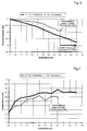
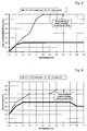
- Fig. 6 zeigt eine graphische Darstellung der Ergebnisse des Vergleichsversuchs bezüglich der Abnahme des maximalen Schneidperlendurchmessers mit steigender Schnittfläche.
- Fig. 7 zeigt eine graphische Darstellung der Ergebnisse des Vergleichsversuchs bezüglich der Zeitspanfläche.
- Fig. 8 zeigt eine graphische Darstellung der Ergebnisse des Vergleichsversuchs bezüglich der maximalen Rundheitsabweichung der Schneidperlen.
- Fig. 9 zeigt eine graphische Darstellung der Ergebnisse des Vergleichsversuchs bezüglich der maximalen Konizität der Schneidperlen.
- Fig. 1 shows an embodiment of a saw rope turning device, in which the saw rope is driven by a separate drive unit;
The rope rotating roller (1) is arranged immediately before entry into the material, an already performed rotation of individual beads on a saw cable (2) being fixed via the friction when entering the material to be processed. The rope rotating roller (1) has a rubber or plastic pad, and a guide roller (3) is provided, the arrangement of which according to the rope rotating roller (1) is shown in Fig. 3 in more detail. - Fig. 2 shows a schematic representation in the region of a rope rotating roller acting as a rope drive. In the embodiment according to FIG. 2, the wrap angle ρ is 180 °, and the guide roller (3 ') is arranged normally to the rope rotating roller (1').
- Fig. 3 shows a schematic representation of rope rotating roller (1) and guide roller (3) to explain the wrap angle (ρ), the roller distance (d) and the entry angle (γ). 3, the wrap angle ρ of the saw cable (2) around the rope rotating roller (1) is 106 °, the roller distance e between rope rotating roller (1) and guide roller e 1.3xD and the entry angle γ 4.5 °. (D), as can be seen from FIG. 4, the effective diameter from the middle of the rope to the middle of the rope between the inlet and outlet side, based on the axis of rotation of the rope rotating roller (1). In Fog. 3, the curved course of the saw cable (2) is clearly visible during the lateral rolling between the cable entry and exit areas of the cable rotating roller (1).
- Fig. 4 shows schematically a section through a rope rotating roller (1) for explaining the saw rope system conditions with the inlet side at the bottom and the outlet side at the top, a wrap angle ρ = 180 ° and a cone angle β of 25 ° being provided. This indicates the offset q and a distance s by which the saw cable (2) with the diameter d rolls down the cone.
- In Fig. 5, exemplary embodiments for rope rotating roller profiles are shown schematically, profiles A and D being preferred for one running direction and profiles B, C, E and F being preferred for both running directions.
- FIG. 6 shows a graphical representation of the results of the comparison test with regard to the decrease in the maximum diameter of the cutting pearls with increasing cutting area.
- FIG. 7 shows a graphical representation of the results of the comparative experiment with respect to the chip removal area.
- 8 shows a graphical representation of the results of the comparative experiment with regard to the maximum roundness deviation of the cutting beads.
- FIG. 9 shows a graphical representation of the results of the comparison test with regard to the maximum conicity of the cutting beads.
Das Grundprinzip der Seildrehvorrichtung basiert auf einer vorzugsweise konisch geformten Rolle (1) mit Gummi- oder Kunststoffauflage. Wird nun ein Sägeseil (2) auf dem größeren Durchmesser des konischen Rollenprofils zugeführt, wird es im weiteren Verlauf auf der Rolle (1) versuchen, bedingt durch die Zugkraft im Sägeseil, auf den kleineren Durchmesser der Rolle um den Betrag (s) in Fig. 4 abzuwandern. Da die Reibung zwischen den Diamantperlen und der Auflage auf der Rolle sehr groß ist, wird das Seil dabei veranlaßt, diese Abwanderung in Form von Rollbewegungen und nicht durch Abrutschen zurückzulegen. Damit ist die Drehbewegung generiert und muß über den elastischen Verdrehwiderstand des Seiles an den übrigen Teil des Seiles weitergegeben werden. Diese Drehbewegung wird wirkungsvoll weitergegeben, wenn das Seil bereits vor dem Einsatz mit ca. 2 Umdrehungen pro Laufmeter Seil voreingedreht wurde.The basic principle of the rope rotating device is based on a preferably conically shaped roller (1) with a rubber or plastic covering. If a saw cable (2) is now fed onto the larger diameter of the conical roller profile, it will try on the roller (1) in the further course, due to the tensile force in the saw cable, to the smaller diameter of the roller by the amount (s) in Fig 4 to migrate. Since the friction between the diamond pearls and the support on the reel is very large, the rope is caused to move in the form of rolling movements and not by slipping. The rotary movement is thus generated and must be passed on to the remaining part of the rope via the elastic torsional resistance of the rope. This rotary movement is effectively passed on if the rope was pre-twisted with approx. 2 revolutions per linear meter of rope before use.
Eine optimale Position für die Anordnung der Seildrehrolle (1) ist unmittelbar vor dem Eintritt in den Werkstoff entsprechend Fig. 1, denn eine bereits durchgeführte Drehung der einzelnen Perlen wird beim Eintritt in das Material über die Reibung fixiert, eine elastische Rückdrehung ist damit unterbunden. Grundsätzlich kann jedoch auch das Antriebsrad (1') gemäß Fig. 2 als Seildrehrolle ausgebildet werden, was vor allem bei kurzen Seillängen vorteilhaft ist.An optimal position for the arrangement of the rope rotating roller (1) is immediately before entering the material in accordance with FIG. 1, because an already performed rotation of the individual beads is fixed via the friction when entering the material, an elastic backward rotation is thus prevented. In principle, however, the drive wheel (1 ') according to FIG. 2 can also be designed as a rope rotating roller, which is particularly advantageous for short rope lengths.
Der Umschlingungswinkel ρ gemäß Fig. 3 kann ausgehend von sehr geringen Winkeln von ca. 30° bis zum Sonderfall von 360° entsprechend einer vollen Umschlingung betragen. Beim Sonderfall der vollen Umschlingung muß durch konstruktive Maßnahmen verhindert werden, daß einander die auf der Seildrehrolle ein- und auslaufenden Seilteile nicht berühren. Bei Berührung der beiden Seilteile ist mit hohem Verschleiß zu rechnen, weil die Relativgeschwindigkeit am Berührungspunkt aufgrund der häufig verwendeten Schnittgeschwindigkeit von 21 (m/s) etwa 3 (m/s) beträgt, wie im Rechenbeispiel in der Tabelle 1 für die praktischen Einsatzdaten ermittelt wurde.The wrap angle ρ according to FIG. 3 can start from very small angles of approximately 30 ° to the special case of 360 ° corresponding to a full wrap be. In the special case of full wrap, constructive measures must be taken to ensure that the rope parts entering and leaving the rope rotating roller do not touch each other. High wear is to be expected when touching the two rope parts because the relative speed at the point of contact is about 3 (m / s) due to the frequently used cutting speed of 21 (m / s), as determined in the calculation example in Table 1 for the practical application data has been.
Der Konuswinkel β in Fig. 4 beeinflußt nur die Kraftkomponente Fr, mit der das Seil zur Rollbewegung gezwungen wird, nicht jedoch die Drehfrequenz des Seiles um seine Achse. Die Seildrehrolle funktionierte sicher in den Versuchsserien ab β = 10° bei einem Umschlingungswinkel von ρ = 360°, die besten Ergebnisse wurden bei β = 25° und einem Umschlingungswinkel von ρ = 90° bis 180° erzielt.The cone angle β in FIG. 4 only influences the force component F r with which the rope is forced to roll, but not the frequency of rotation of the rope about its axis. The rope rotating pulley worked reliably in the test series from β = 10 ° with a wrap angle of ρ = 360 °, the best results were achieved with β = 25 ° and a wrap angle of ρ = 90 ° to 180 °.
In Anlehnung an das Konusprofil sind erfindungsgemäß abgewandelte Rollenprofile denkbar, wie beispielhaft in der Fig. 5 angeführt. Das erfindungsgemäße Grundprinzip des Abrollens des Seiles im Laufe des im Umschlingungswinkel ρ zurückgelegten Weges bleibt von der Ausführungsform des Seillaufprofils weitgehend unbeeinflußt. Es muß jedoch grundsätzlich zwischen ein- und zweiseitig wirkenden Profilen unterschieden werden. Bei einseitigen Profilen wie A und D in Fig. 5 kann eine Laufrichtungsänderung zum Blockieren des Seiles führen. Bei Maschinen mit Laufrichtungsänderung und 360° Umschlingungswinkel ρ an der Seildrehrolle 1 wird das Seillaufprofil vorzugsweise symmetrisch ausgeführt.On the basis of the cone profile, roller profiles modified according to the invention are conceivable, as exemplified in FIG. 5. The basic principle according to the invention of the unwinding of the rope in the course of the path covered in the wrap angle ρ remains largely unaffected by the embodiment of the rope running profile. However, a basic distinction must be made between one-way and two-way profiles. In the case of unilateral profiles such as A and D in FIG. 5, a change in the running direction can lead to the rope being blocked. In machines with a change of direction and a 360 ° wrap angle ρ on the
Die Distanz q zwischen Seileinlauf und Seilauslauf auf der Seildrehrolle bestimmt im wesentlichen die Drehfrequenz des Seiles entsprechend der Berechnung der Drehwirkung im anschließenden Rechenbeispiel. Wie die Versuche zeigten, genügt bereits eine eingestellte Distanz q von 2-4 mm für einen sicheren Seildreheffekt. Wesentlich höhere q-Werte erzeugten schädliche Schwingungen im Seil, sollten also vermieden werden.The distance q between the rope inlet and the rope outlet on the rope rotating roller essentially determines the frequency of rotation of the rope in accordance with the calculation of the turning effect in the following calculation example. As the tests showed, a set distance q of 2-4 mm is sufficient for a reliable rope turning effect. Significantly higher q values generated harmful vibrations in the rope, so they should be avoided.
Das Seil mit dem Ø d wird beim Umlauf um die Seildrehrolle (1) (1') um eine Distanz q versetzt und muß daher die Strecke s den Konus hinunterrollen.
![]()
Während einer Drehung der Seildrehrolle (1) (1') mit dem Durchmesser D um den Umschlingungswinkel ρ dreht sich dabei eine Perle, unabhängig von D um den Winkel
![]()
oder anders ausgedrückt um ![]()
![]()
During a rotation of the rope rotating roller (1) (1 ') with the diameter D by the wrap angle ρ, a pearl rotates independently of D by the angle
![]()
or in other words around ![]()
Die Länge des auf dem Konus (4) befindlichen Sägeseiles (2) wird durch den Durchmesser D der Seildrehrolle (1) und den Umschlingungswinkel ρ bestimmt.
![]()
Da das Sägeseil (2) sich dabei wie oben beschrieben n mal dreht, ergibt dies pro Laufmeter Seil eine Verdrehung des Seiles von:
![]()
Auf die gesamte Seillänge L gesehen, ergibt dies eine Anzahl von Eindrehungen
![]()
Da das Seil mit der Geschwindigketi Vs bewegt wird, werden pro Zeiteinheit m Drehungen durchlaufen.
![]()
Aus der Drehzahl m ergibt sich die Drehgeschwindigkeit des Perlenumfanges nach folgender Formel:
![]()
Bei Zugrundelegung von Standardparametern wird für verschiedene Seilversatzwerte q die Drehwirkung berechnet und in Tabelle 1 dargestellt:

![]()
Since the saw cable (2) rotates n times as described above, this results in the rope twisting per linear meter of:
![]()
Viewed over the entire rope length L, this results in a number of turns
![]()
Since the rope is moved with the speed V s , m turns are carried out per unit of time.
![]()
The speed of rotation of the pearl circumference results from the speed m according to the following formula:
![]()
Based on standard parameters, the turning effect is calculated for various rope misalignment values q and shown in Table 1:
Der Seileinlauf kann durch Vorschalten einer Führungsrolle (3) in beliebiger Entfernung (e) vorzugsweise ca. 1 bis 2 mal dem Durchmesser der Seildrehrolle (1) erfolgen. Die Achse dieser Führungsrolle (3) kann dabei in einem Einlaufwinkel (γ) zur Seildrehrolle (1) stehen, um einen schonenden Seillauf zu ermöglichen. Vorteilhaft verwendet man eine handelsübliche selbsteinstellende Schwenkrolle.The rope can be run in by connecting a guide roller (3) at any distance (e), preferably approx. 1 to 2 times the diameter of the rope rotating roller (1). The axis of this guide roller (3) can be at an entry angle (γ) to the rope rotating roller (1) to enable a gentle rope run. It is advantageous to use a commercially available self-adjusting swivel castor.
Bei durchgeführten Schneidversuchen nach Ausführungsbeispiel gemäß Fig. 1 und Fig. 3 wurde ab Konuswinkel β = 5 ° die erfindungsgemäße fortlaufende Drehung des Sägeseils erreicht. Bei Konuswinkeln ab etwa 45° ist Schlupf zwischen Seil und Rolle aufgetreten, was im Dauerbetrieb zu vorzeitigem Verschleiß des Rollenbelages führen könnte.In the case of cutting tests carried out according to the exemplary embodiment according to FIG. 1 and FIG. 3, the continuous rotation of the saw cable according to the invention was achieved from a cone angle β = 5 °. At cone angles of around 45 ° or more, slippage has occurred between the rope and the reel, which could lead to premature wear of the roller lining in continuous operation.
Die Anordnung nach Fig. 1 und Fig. 3 stellt eine mögliche Ausführungsform der Erfindung der Seildrehvorrichtung dar. Es sind jedoch Ergänzungen mit zusätzlichen Führungsrollen im Seileinlauf und Seilauslauf etwa zur Dämpfung von Seilschwingungen bei langen Seillängen denkbar, ohne daß dieselben die erfindungsgemäße Wirkung der eigentlichen Seildrehvorrichtung beeinflussen. Desgleichen hat eine umgekehrte Anordnung von Seildrehrolle (1) und Führungsrolle (3) bezüglich der Seilschnittrichtung keine einschränkende Wirkung auf das Ziel der Erfindung, da bei umgekehrter Seilschnittrichtung lediglich die Verdrehrichtung des Seiles um seine Achse sich ebenfalls umkehrt, und sonst keinerlei Wirkung auf die erfindungsgemäße ständige Drehung feststellbar war.The arrangement according to FIGS. 1 and 3 represents a possible embodiment of the invention of the rope turning device. However, additions with additional guide rollers in the rope inlet and rope outlet are conceivable, for example, for damping rope vibrations with long rope lengths, without the same effect according to the invention of the actual rope turning device influence. Likewise, an inverted arrangement of the rope rotating roller (1) and the guide roller (3) with respect to the direction of the rope cutting has no restrictive effect on the aim of the invention, since in the opposite direction of the rope cutting only the direction of rotation the rope around its axis is also reversed, and otherwise no effect on the constant rotation according to the invention was found.
Der nachfolgend beschriebene Seilsägeversuch zeigte, daß die erfindungsgemäße stetige Drehbewegung des Seiles, erzeugt durch die speziell geformte Seildrehrolle nach einem der Beispiele (A) - (F) in Fug. 5, einen gleichmäßigen Verschleiß der Perlen sicherstellt (Rundheitsabweichung ≦ 0,2 mm). Mit der Rollenanordnung nach Fig. 1 und Fig. 3 wurde ein sehr konstantes Schneidverhalten ohne Seilschwingungen sowie eine gute Regelbarkeit des Seilsägevorganges erreicht. Mit der nach Fig. 1, 3 und 4 angebrachten Seildrehrolle konnte eine Erhöhung der Zerspanungsleistung um durchschnittlich 6 % erzielt werden. Die graphische Zusammenfassung der Versuchsergebnisse finden sich in den Fig. 6-9. Es wurde ein handelsübliches Diamantseil der TYROLIT Schleifmittelwerke Schwaz mit der Typenbezeichnung "H41 4 25" verwendet.The rope saw test described below showed that the continuous rotary movement of the rope according to the invention, generated by the specially shaped rope rotating roller according to one of the examples (A) - (F) in Fug. 5, ensures even wear of the beads (roundness deviation ≦ 0.2 mm). With the roller arrangement according to FIGS. 1 and 3, a very constant cutting behavior without rope vibrations and good controllability of the wire sawing process were achieved. 1, 3 and 4 attached rope turning roller, an increase in the cutting performance by an average of 6% could be achieved. The graphic summary of the test results can be found in FIGS. 6-9. A commercially available diamond rope from TYROLIT Schleifmittelwerke Schwaz with the type designation "
- 11
- SeildrehrolleRope roll
- 1'1'
- Seildrehrolle als Antriebsrolle der SeilsägemaschineRope turning roller as the driving roller of the rope saw machine
- 22nd
- SägeseilSaw rope
- 33rd
- FührungsrolleLeadership role
- 3'3 '
- Führungsrolle bei Seildrehrolle als AntriebsrolleLeading role with rope rotating role as driving role
- 44th
- Rollenprofil der SeildrehrolleRoll profile of the rope rotating pulley
- ββ
- KonuswinkelCone angle
- ρρ
- UmschlingungswinkelWrap angle
- seitlicher Abstand zwischen Seileinlauf und Seilauslauflateral distance between rope inlet and rope outlet
- γγ
- EinlaufwinkelEntry angle
- ss
- AbrollbetragUnwind amount
Claims (10)
Priority Applications (1)
| Application Number | Priority Date | Filing Date | Title |
|---|---|---|---|
| PCT/EP1993/002896 WO1994008746A1 (en) | 1992-10-21 | 1993-10-21 | Rotating mechanism for a cutting strand |
Applications Claiming Priority (2)
| Application Number | Priority Date | Filing Date | Title |
|---|---|---|---|
| AT0208092A AT398935B (en) | 1992-10-21 | 1992-10-21 | SAW ROPE TURNING DEVICE |
| AT2080/92 | 1992-10-21 |
Publications (2)
| Publication Number | Publication Date |
|---|---|
| EP0593899A1 true EP0593899A1 (en) | 1994-04-27 |
| EP0593899B1 EP0593899B1 (en) | 1997-04-16 |
Family
ID=3527332
Family Applications (1)
| Application Number | Title | Priority Date | Filing Date |
|---|---|---|---|
| EP93114729A Expired - Lifetime EP0593899B1 (en) | 1992-10-21 | 1993-09-14 | Saw wire rotating device |
Country Status (3)
| Country | Link |
|---|---|
| EP (1) | EP0593899B1 (en) |
| AT (2) | AT398935B (en) |
| DE (2) | DE9313907U1 (en) |
Cited By (3)
| Publication number | Priority date | Publication date | Assignee | Title |
|---|---|---|---|---|
| EP0694366A1 (en) * | 1994-07-29 | 1996-01-31 | Shin-Etsu Handotai Company Limited | Wire saw apparatus |
| EP2216117A1 (en) * | 2009-02-10 | 2010-08-11 | Betag-Betontaglio SA | Rope saw and method for operating same |
| CN114033366A (en) * | 2021-10-15 | 2022-02-11 | 长沙百川超硬材料工具有限公司 | Method for self-rotating of sawing rope of rope sawing machine |
Families Citing this family (1)
| Publication number | Priority date | Publication date | Assignee | Title |
|---|---|---|---|---|
| DE19936834A1 (en) * | 1999-08-05 | 2001-02-15 | Wacker Siltronic Halbleitermat | Saw wire and method for lapping severely brittle workpieces |
Citations (3)
| Publication number | Priority date | Publication date | Assignee | Title |
|---|---|---|---|---|
| FR778280A (en) * | 1934-09-13 | 1935-03-13 | Installation for mechanical marble work | |
| US3682030A (en) * | 1970-11-04 | 1972-08-08 | Gerald R Harris | Pivotal arm band saw |
| FR2655904A1 (en) * | 1989-12-14 | 1991-06-21 | Diamind Sa | System of the "cable" type for cutting solid bodies |
Family Cites Families (7)
| Publication number | Priority date | Publication date | Assignee | Title |
|---|---|---|---|---|
| DE189787C (en) * | ||||
| US1050896A (en) * | 1912-06-25 | 1913-01-21 | Harry Wilson | Sheave-block. |
| FR1199566A (en) * | 1958-03-06 | 1959-12-15 | Reel for sawing wire, and sawing machines using this reel | |
| GB1491614A (en) * | 1974-06-11 | 1977-11-09 | Graham R | Winches |
| SU684241A1 (en) * | 1978-02-10 | 1979-09-05 | Украинский научно-исследовательский и проектно-конструкторский институт подземной гидравлической добычи угля "УкрНИИгидроуголь" | Multiple rope-guiding pulley |
| SU688753A1 (en) * | 1978-03-14 | 1979-09-30 | Украинский Научно-Исследовательский И Проектно-Конструкторский Институт Подземной Гидравлической Добычи Угля | Multipass rope-guding sheave |
| FR2645518B1 (en) * | 1989-04-05 | 1991-08-16 | Brenot Claude | SELF-HOLDING CAPSTAN WITH ARTICULATED TEETH |
-
1992
- 1992-10-21 AT AT0208092A patent/AT398935B/en not_active IP Right Cessation
-
1993
- 1993-09-14 EP EP93114729A patent/EP0593899B1/en not_active Expired - Lifetime
- 1993-09-14 DE DE9313907U patent/DE9313907U1/en not_active Expired - Lifetime
- 1993-09-14 DE DE59306169T patent/DE59306169D1/en not_active Expired - Fee Related
- 1993-09-14 AT AT93114729T patent/ATE151675T1/en active
Patent Citations (3)
| Publication number | Priority date | Publication date | Assignee | Title |
|---|---|---|---|---|
| FR778280A (en) * | 1934-09-13 | 1935-03-13 | Installation for mechanical marble work | |
| US3682030A (en) * | 1970-11-04 | 1972-08-08 | Gerald R Harris | Pivotal arm band saw |
| FR2655904A1 (en) * | 1989-12-14 | 1991-06-21 | Diamind Sa | System of the "cable" type for cutting solid bodies |
Cited By (4)
| Publication number | Priority date | Publication date | Assignee | Title |
|---|---|---|---|---|
| EP0694366A1 (en) * | 1994-07-29 | 1996-01-31 | Shin-Etsu Handotai Company Limited | Wire saw apparatus |
| US5907988A (en) * | 1994-07-29 | 1999-06-01 | Shin-Etsu Handotai Co., Ltd. | Wire saw apparatus |
| EP2216117A1 (en) * | 2009-02-10 | 2010-08-11 | Betag-Betontaglio SA | Rope saw and method for operating same |
| CN114033366A (en) * | 2021-10-15 | 2022-02-11 | 长沙百川超硬材料工具有限公司 | Method for self-rotating of sawing rope of rope sawing machine |
Also Published As
| Publication number | Publication date |
|---|---|
| AT398935B (en) | 1995-02-27 |
| ATA208092A (en) | 1994-07-15 |
| DE9313907U1 (en) | 1993-11-25 |
| EP0593899B1 (en) | 1997-04-16 |
| DE59306169D1 (en) | 1997-05-22 |
| ATE151675T1 (en) | 1997-05-15 |
Similar Documents
| Publication | Publication Date | Title |
|---|---|---|
| EP0496049A1 (en) | Improvement to the device for feeding a cable into an automatic cable manufacturing machine | |
| DE2353895B2 (en) | DEVICE FOR CUTTING GLASS PIECES | |
| DE3308586C2 (en) | Device for centerless, external machining of elongated workpieces | |
| DE1928201A1 (en) | Method and device for the production of endless objects | |
| DE3128110A1 (en) | "METHOD AND DEVICE FOR CUTTING FLANK-OPEN V-BELTS" | |
| DE60111798T2 (en) | High-speed cutting device for cutting reinforcing elements for pneumatic tires. | |
| EP0593899B1 (en) | Saw wire rotating device | |
| DE2321477A1 (en) | METHOD AND DEVICE FOR DRESSING AND SHARPENING GRINDING WHEELS | |
| WO1997017179A1 (en) | Device for smoothing panels or battens | |
| DE2931958A1 (en) | CABLE | |
| DE102006058819B4 (en) | A method of separating a plurality of slices from a workpiece | |
| EP0088347B1 (en) | Apparatus for keeping the tension of metal strips at a constant level | |
| DE19808804A1 (en) | Apparatus for roughening the surfaces of textile piecegoods | |
| WO1994008746A1 (en) | Rotating mechanism for a cutting strand | |
| DE2504696C3 (en) | Chain tensioning device for chain-operated machines, in particular in mining | |
| DE102010021959A1 (en) | saw cable | |
| DE4239212A1 (en) | Wire saw machine e.g. for jigsaw work - uses endless thin wire automatically tensioned by spring-loaded rollers | |
| DE69808879T2 (en) | Device for cleaning wire for the production of drawn metal wires | |
| DE2740212C2 (en) | Saw band roll | |
| DE3040829A1 (en) | METHOD FOR DAMPING THE VIBRATIONS OF AN EXTENSIVE, BENDABLE TOOL, AND A MACHINE PROVIDED WITH A TOOL VIBRATION DAMPING DEVICE | |
| DE69608005T2 (en) | Conveyor device for bulk goods | |
| DE10332711A1 (en) | Belt for winding device | |
| DE4217808A1 (en) | Removal of exposed cords when slitting belts during mfr. - using shaped grindstone which removes cords without grinding side of belt | |
| EP1297924A1 (en) | Wire saw | |
| DE3916289A1 (en) | SCAFFOLDING FOR TOWING OR BRAKING TAPES |
Legal Events
| Date | Code | Title | Description |
|---|---|---|---|
| PUAI | Public reference made under article 153(3) epc to a published international application that has entered the european phase |
Free format text: ORIGINAL CODE: 0009012 |
|
| AK | Designated contracting states |
Kind code of ref document: A1 Designated state(s): AT BE CH DE DK ES FR GB IT LI NL PT SE |
|
| 17P | Request for examination filed |
Effective date: 19940301 |
|
| GBC | Gb: translation of claims filed (gb section 78(7)/1977) | ||
| GRAG | Despatch of communication of intention to grant |
Free format text: ORIGINAL CODE: EPIDOS AGRA |
|
| GRAH | Despatch of communication of intention to grant a patent |
Free format text: ORIGINAL CODE: EPIDOS IGRA |
|
| GRAH | Despatch of communication of intention to grant a patent |
Free format text: ORIGINAL CODE: EPIDOS IGRA |
|
| 17Q | First examination report despatched |
Effective date: 19961004 |
|
| GRAA | (expected) grant |
Free format text: ORIGINAL CODE: 0009210 |
|
| AK | Designated contracting states |
Kind code of ref document: B1 Designated state(s): AT BE CH DE DK ES FR GB IT LI NL PT SE |
|
| PG25 | Lapsed in a contracting state [announced via postgrant information from national office to epo] |
Ref country code: NL Effective date: 19970416 Ref country code: IT Free format text: LAPSE BECAUSE OF FAILURE TO SUBMIT A TRANSLATION OF THE DESCRIPTION OR TO PAY THE FEE WITHIN THE PRE;WARNING: LAPSES OF ITALIAN PATENTS WITH EFFECTIVE DATE BEFORE 2007 MAY HAVE OCCURRED AT ANY TIME BEFORE 2007. THE CORRECT EFFECTIVE DATE MAY BE DIFFERENT FROM THE ONE RECORDED.SCRIBED TIME-LIMIT Effective date: 19970416 Ref country code: FR Effective date: 19970416 Ref country code: ES Free format text: THE PATENT HAS BEEN ANNULLED BY A DECISION OF A NATIONAL AUTHORITY Effective date: 19970416 Ref country code: DK Effective date: 19970416 |
|
| REF | Corresponds to: |
Ref document number: 151675 Country of ref document: AT Date of ref document: 19970515 Kind code of ref document: T |
|
| REG | Reference to a national code |
Ref country code: CH Ref legal event code: EP |
|
| REF | Corresponds to: |
Ref document number: 59306169 Country of ref document: DE Date of ref document: 19970522 |
|
| GBT | Gb: translation of ep patent filed (gb section 77(6)(a)/1977) |
Effective date: 19970606 |
|
| PG25 | Lapsed in a contracting state [announced via postgrant information from national office to epo] |
Ref country code: SE Effective date: 19970716 Ref country code: PT Effective date: 19970716 |
|
| NLV1 | Nl: lapsed or annulled due to failure to fulfill the requirements of art. 29p and 29m of the patents act | ||
| PGFP | Annual fee paid to national office [announced via postgrant information from national office to epo] |
Ref country code: AT Payment date: 19970903 Year of fee payment: 5 |
|
| EN | Fr: translation not filed | ||
| PG25 | Lapsed in a contracting state [announced via postgrant information from national office to epo] |
Ref country code: BE Free format text: LAPSE BECAUSE OF NON-PAYMENT OF DUE FEES Effective date: 19970930 |
|
| PGFP | Annual fee paid to national office [announced via postgrant information from national office to epo] |
Ref country code: CH Payment date: 19971029 Year of fee payment: 5 |
|
| PGFP | Annual fee paid to national office [announced via postgrant information from national office to epo] |
Ref country code: GB Payment date: 19971112 Year of fee payment: 5 |
|
| PLBE | No opposition filed within time limit |
Free format text: ORIGINAL CODE: 0009261 |
|
| STAA | Information on the status of an ep patent application or granted ep patent |
Free format text: STATUS: NO OPPOSITION FILED WITHIN TIME LIMIT |
|
| BERE | Be: lapsed |
Owner name: TYROLIT SCHLEIFMITTELWERKE SWAROVSKI K.G. Effective date: 19970930 |
|
| 26N | No opposition filed | ||
| PG25 | Lapsed in a contracting state [announced via postgrant information from national office to epo] |
Ref country code: DE Free format text: LAPSE BECAUSE OF NON-PAYMENT OF DUE FEES Effective date: 19980603 |
|
| PG25 | Lapsed in a contracting state [announced via postgrant information from national office to epo] |
Ref country code: GB Free format text: LAPSE BECAUSE OF NON-PAYMENT OF DUE FEES Effective date: 19980914 Ref country code: AT Free format text: LAPSE BECAUSE OF NON-PAYMENT OF DUE FEES Effective date: 19980914 |
|
| PG25 | Lapsed in a contracting state [announced via postgrant information from national office to epo] |
Ref country code: LI Free format text: LAPSE BECAUSE OF NON-PAYMENT OF DUE FEES Effective date: 19980930 Ref country code: CH Free format text: LAPSE BECAUSE OF NON-PAYMENT OF DUE FEES Effective date: 19980930 |
|
| GBPC | Gb: european patent ceased through non-payment of renewal fee |
Effective date: 19980914 |
|
| REG | Reference to a national code |
Ref country code: CH Ref legal event code: PL |