EP0593236A1 - Method and apparatus for corrugating sheet material - Google Patents
Method and apparatus for corrugating sheet material Download PDFInfo
- Publication number
- EP0593236A1 EP0593236A1 EP93308065A EP93308065A EP0593236A1 EP 0593236 A1 EP0593236 A1 EP 0593236A1 EP 93308065 A EP93308065 A EP 93308065A EP 93308065 A EP93308065 A EP 93308065A EP 0593236 A1 EP0593236 A1 EP 0593236A1
- Authority
- EP
- European Patent Office
- Prior art keywords
- sheet
- forming
- thermo
- sheet material
- temperature
- Prior art date
- Legal status (The legal status is an assumption and is not a legal conclusion. Google has not performed a legal analysis and makes no representation as to the accuracy of the status listed.)
- Granted
Links
Images


Classifications
-
- B—PERFORMING OPERATIONS; TRANSPORTING
- B29—WORKING OF PLASTICS; WORKING OF SUBSTANCES IN A PLASTIC STATE IN GENERAL
- B29C—SHAPING OR JOINING OF PLASTICS; SHAPING OF MATERIAL IN A PLASTIC STATE, NOT OTHERWISE PROVIDED FOR; AFTER-TREATMENT OF THE SHAPED PRODUCTS, e.g. REPAIRING
- B29C53/00—Shaping by bending, folding, twisting, straightening or flattening; Apparatus therefor
- B29C53/22—Corrugating
- B29C53/24—Corrugating of plates or sheets
- B29C53/26—Corrugating of plates or sheets parallel with direction of feed
-
- B—PERFORMING OPERATIONS; TRANSPORTING
- B29—WORKING OF PLASTICS; WORKING OF SUBSTANCES IN A PLASTIC STATE IN GENERAL
- B29K—INDEXING SCHEME ASSOCIATED WITH SUBCLASSES B29B, B29C OR B29D, RELATING TO MOULDING MATERIALS OR TO MATERIALS FOR MOULDS, REINFORCEMENTS, FILLERS OR PREFORMED PARTS, e.g. INSERTS
- B29K2069/00—Use of PC, i.e. polycarbonates or derivatives thereof, as moulding material
Definitions
- the invention is directed to a method and apparatus for thermo-forming sheet material, and particularly to a method and apparatus for corrugating amorphous materials having low melt strength at forming temperatures.
- High melt strength sheet materials may be corrugated by drawing or extruding heated sheet material through a calibrator having the profile corresponding to the desired final shape.
- Low melt strength materials may not be readily formed by this method because pulling or drawing forces may exceed the strength of the material above the glass transition temperature. If the material is extruded below the glass transition temperature, the pulling force may be excessive and, in addition, the sheet material may be damaged by the calibrator or extruder friction.
- One way to reduce the friction is to use rollers to deform the sheet material. However, certain materials such as polycarbonates have the tendency to shrink back from the deformed shape as the material cools below the glass transition temperature.
- the present invention obviates and eliminates the disadvantages and shortcomings of the described prior arrangements.
- the present invention is based upon the discovery that a pair of thermo-forming rollers and a calibrator having an inlet in closely spaced conforming relationship with the deforming rollers is capable of producing corrugated thermo-formed sheet.
- the invention is directed to an apparatus for continuously corrugating a supply of thermo-formable sheet material having a low melt strength at forming temperatures comprising means for laterally engaging the sheet and transporting it from a supply through a forming stage at a selected rate.
- the apparatus further includes a heating zone for receiving the sheet material therein and for raising its temperature to the forming temperature.
- a pair of opposed interdigitated forming rollers adjacent the heating zone outlet receives the sheet material therebetween in a nip for thermo-forming corrugations in the sheet.
- a cooled calibrator having a profile corresponding to the formed corrugation receives the thermo-formed sheet and maintains the thermo-formed corrugations therein until the material cools below the forming temperature.
- the calibrator has an upstream end shaped for closely conforming to the rollers and is disposed in close proximity to the nip of the forming rollers.
- a differential drive simultaneously carries the thermo-formable sheet through the heating zone and into the thermo-forming region and draws the thermo-formed sheet from the calibrator at a draw rate greater than the feed rate.
- the invention comprises an apparatus for continuously producing corrugated sheet from a supply of sheet material having low melt strength at the forming temperature comprising a carrier for supporting and maintaining the width of a supply of the sheet material along a longitudinal path.
- An oven in the path has a plurality of heating stages. The oven receives the sheet material at an inlet end thereof and raises the temperature of the sheet material to its forming temperature near an outlet end thereof.
- a pair of opposed interdigitated forming rollers located transversely of the path is closely coupled to the outlet of the oven and receives the sheet material heated to its forming temperature therebetween. The forming rollers form corrugations in the heated sheet.
- a cooled calibrator located in the path closely adjacent to the forming rollers has a profiled inlet end transverse of the path.
- the profiled inlet end engages the forming rollers in closely spaced conforming relation for capturing the heated corrugated sheet therein immediately after thermo-forming.
- the calibrator has interdigitated profiled surfaces extending from the inlet end along the path to an outlet end for maintaining the corrugations in the sheet as the heated sheet cools below its forming temperature.
- the invention comprises a method for continuously producing corrugated sheet from a supply of sheet material having a low melt strength at forming temperatures by: heating the material to a forming temperature just above the glass transition temperature; thermo-forming material with rollers while it is above the glass transition temperature; capturing the thermo-formed sheet material for calibration while above its glass transition temperature; and calibrating and cooling the material to below its glass transition temperature.
- thermo-forming apparatus 10 in accordance with the present invention as illustrated in Fig. 1.
- the apparatus is a multi-stage system for supplying, heating, thermo-forming, cooling and discharging corrugated sheet formed of a material which has low melt strength at forming temperatures. During heating and thermo-forming, the material is maintained at a selected uniform width to prevent lateral shrinkage.
- the apparatus 10 includes a supply stage 12, heater stage 14, a thermo-forming stage 16, a cooling stage 18 and a trim/cut/stack or discharge stage 20.
- a supply of thermo-formable sheet material 22 is fed from the feed stage 12 through the heater stage 14, the thermo-forming stage 16, the cooling stage 18 and the discharge stage 20 whereupon different operations are performed to produce sized panels 24 cut to length and width.
- the material or supply 22 is drawn through the apparatus 10 by means of a primary drive 26 downstream of the thermo-forming stage 16.
- a secondary drive 28 upstream of the primary drive 26 laterally supports the sheet 22 and feeds it through the heater stage 14 and the thermo-forming stage 16.
- the secondary drive may extend through at least a portion of the cooling stage located upstream of the primary drive 26.
- the raw material forming the sheet 22 comprises a base layer of polycarbonate flat sheet 31 that is co-extruded with a UV stabilized cap layer 32.
- the thickness of the sheet 22 is dependent upon the application and the finished product thickness. Typically, the thickness for greenhouse applications is 0.033 inch.
- the sheet 22 is wound on one or more supply spools 34 which typically contain between 8,000 and 10,000 feet of sheet material 22.
- the spools 34 are placed into an unwind stand 36 in the supply stage 12.
- the spools may also be carried by movable carts into the supply stage 12 in lieu of using a separate unwind stand 36.
- the spools 34 are threaded over an idler 38 and under a dancer roll 40 in a frame 42 which is retractably mounted in the supply stage 12.
- An additional series of rollers including a secondary dancer roll 44 is provided to stabilize the supply 22.
- a pair of unwind stands 36 and movable frames 42 are provided so as to allow for a resupply of the sheet material 22 as one or the other spool 34 is exhausted.
- the sheet material 22 is supplied in a selected width, e.g., about 59 inches, measured at its marginal edges 46 (Fig. 11).
- Secondary drive 28 in the form of a chain drive 50 receives the sheet 22 upstream of the supply stage 12.
- the chain drive comprises a pair of laterally disposed endless chains 52 (Fig. 11) mounted laterally of the sheet 22 and inboard of its marginal edges 46.
- the chains 52 extend lengthwise of the apparatus 10 upstream of the heater stage 14 and downstream of at least the thermo-forming stage 16.
- the chains 52 are formed of individual links 54 which carry outwardly radially extending pins 56 (Fig. 11).
- the chains 52 are mounted on sprockets 58 for endless rotation in chain drive frame 60 as shown, for example, in Fig. 12.
- a cover 62 may be fixed or hinged to the chain drive frame 60.
- the cover 62 has a slotted portion 64 which is adapted to receive the pins 56 for motion in a downstream direction.
- a channel 66 is formed between the cover
- the supply 22 is threaded into the channel 66 near its marginal edges 46.
- the pins 56 puncture and laterally support the sheet 22 inboard of its marginal edge 46.
- the channel 66 is elongated laterally so as to tolerate variations in the width of the sheet material 22.
- the chain 52 and sprockets 58 which are driven by a motor or a chain drive (not shown) pulls the sheet 22 in the upstream direction through the heater stage 14 and thermo-forming stage 16. At the downstream end of the chain drive 50 near the thermo-forming stage 16, the pins 56 and downstream sprockets 58 disengage from the sheet 22 thereby releasing the lateral support.
- Cooling channels 70 are provided in the frame 60 to maintain the temperature of the chain drive 50 at a desired level which is below the melting point or glass transition temperature of the sheet 22 so as to permit the pins to continuously support the sheet through the heating and thermo-forming stages 14 and 16.
- the primary drive 26 engages the sheet 22 downstream of the thermo-forming stage 16 for drawing it therethrough at a selected draw rate.
- the primary drive 26 comprises a pair of spaced apart upper drive rollers 80 and power driven backup rollers 82 mounted in a frame 84.
- the backup rollers 82 are formed of a metal core 86 which carries a resilient sleeve 88.
- Primary drive rollers 80 engage the thermo-formed sheet material 22 from the top side and drive the sheet 22 in the upstream direction.
- the drive rollers 80 generally comprise a metal core or shaft member 90 carrying a plurality of spaced apart annular drive wheels 92 each of which has a resilient annular sleeve or cover 94.
- the drive rollers 80 and backup rollers 82 engage the sheet material 22 therebetween, for drawing sheet 22 through the apparatus.
- the spaced apart annular drive rollers 80 engage the sheet material 22 at a nip formed with the power driven backup rollers 82 between the corrugations without damaging the structure or surface of the thermo-formed material.
- the heater stage 14 (Figs 1 and 11) generally comprises an enclosed housing 100 having an open inlet or upstream end 102 and a downstream or outlet end 104. Disposed within the housing 100 are a plurality of separately temperature control heater units 106, 108 and 110. The sheet material 22 is carried through the housing 100 from the inlet 102 to the outlet 104 past each of the heater units 106, 108 and 110. The temperature of the heating stage 14 is gradually increased between the inlet 102 and the outlet 104 to bring the temperature of the sheet material 22 just above glass transition temperature T g at the outlet 104. The heater unit 106 initially raises the temperature of the sheet material 22 from room temperature to about T g /2 Of course, different materials may have different glass transition temperatures and may require variations in the temperature build up.
- the initial heater unit 106 in Zone I operates at about 200°F.
- the heating unit 110 in Zone III near the outlet 104 of the housing 100 operates at some temperature above T g in which the sheet material 22 is thermo-formable but which retains its integrity within the apparatus.
- T g the temperature of the final heating Zone III is about 380°F.
- the intermediate heat Zone II is operated at a temperature or temperatures near T g of the sheet 22.
- the temperature of the intermediate heating Zone II ranges from above 1.03 T g to about 0.9 T g .
- the temperature of the intermediate heater 108 is highest near the marginal edges 46, e.g., about 1 to 3 percent higher than T g to about 0.9 T g near the center of the sheet 22.
- the reason for the grading of the temperature across the sheet 22 is to compensate for heat losses which may occur near the lateral margins 112 of each of the heating elements 106, 108 and 110.
- each of the heating zones may be temperature controlled to provide a gradiation of temperature across the sheet 22.
- thermo-forming stage 16 is located in close proximity to the outlet 104 of the heating stage 14. Thus, the sheet material 22 is carried into the thermo-forming stage 16 at or above T g its thermo-forming temperature. Of course the thermo-forming stage 16 may be spaced from the heating stage 14 if desired. However, it has been found that closely spacing the respective heating and thermo-forming regions 14 and 16 results in satisfactory thermo-forming of the sheet material 22.
- the thermo-forming stage 16 comprises a pair of interdigitated temperature controlled, power driven thermo-forming rollers 118 and 120 which receive the sheet material 22 therebetween from the outlet 104 of the heating stage 14.
- the thermo-forming rollers 118 and 120 are sometimes mentioned with reference to their respective upper and lower positions.
- a calibrator 122 is closely coupled to the downstream side of the thermo-forming rollers 118 and 120.
- the thermo-forming rollers 118 and 120 deform the sheet material 22 above the thermo-forming temperature and the calibrator 122 captures and maintains the shape of the thermo-formed material as it cools below the glass transition temperature.
- the rollers 118 and 120 each comprise a respective core roller 124 and 125 and a plurality of axially spaced annular forming rollers 126 and 127.
- the rollers 118 and 120 are adjustable along the core 124 and 125 and are arranged so that the annular forming rollers 126 and 127 are interdigitated as shown.
- the rollers 126 and 127 are each removable from its core 124 and 125.
- the sheet material 22 is captured between the forming rollers 118 and 120 whereby it is formed into the corrugated shape shown having peaks 128 and troughs 130 corresponding to the deformations attributable to the respective lower and upper annular forming rollers 126 and 127.
- the core rollers 124 and 125 may include internal passages (not shown) for receiving a temperature controlled supply of fluid, (e.g., heated water) therethrough.
- a temperature controlled supply of fluid e.g., heated water
- the heated water maintains the thermo-forming rollers 118 and 120 at the proper forming temperature.
- the forming rollers 118 and 120 are driven by an electric motor (not shown) and are syncronized with the secondary drive 28.
- the forming rollers 126 may be readily removed from the core rollers 124 and 125 and alternative rollers may be substituted having different profiles to change the shape of the corrugations. For example, different height and width and curative profiles may be readily achieved.
- the calibrator 122 is located on the downstream side of the forming members 118 and 120 in closely conforming spaced relationship.
- the calibrator 122 comprises a pair of spaced apart interdigitated members 140 and 142.
- the upper members 140 engage the valleys 130 of the thermo-formed sheet material 22 and the lower members 142 engage the peaks 128 of the deformed sheet whereby the corrugated shape is maintained as the sheet material 22 is drawn therethrough.
- the respective upper and lower calibrator members 140 and 142 each have an upstream end 144 and a downstream end 146.
- the upstream end 144 is shaped so as to closely conform with the shape of the respective forming rollers 118 and 120 (Fig 3A). That is, the upstream ends 144 of the calibrating members 140 and 142 are in closely spaced conforming relationship with the corresponding forming rollers 118 and 120. This arrangement allows the sheet material 22 to be readily captured as soon as possible after it leaves the forming rollers 118 and 120.
- the purpose of the forming rollers 118 and 120 is to form the corrugations, namely the peaks and valleys 128 and 130, and the purpose of the calibrator 122 is to hold and maintain the desired shape of the corrugated sheet while allowing the material to cool below the glass transition temperature whereby the deformations will set at the desired shape.
- the close proximity of the calibrator elements 140 and 142 to the corresponding forming rollers 118 and 120 achieves this purpose and in addition prevents undesirable thermo-deformations including sag, warpage and twisting of the thermo-formed sheet.
- the calibration members 140 and 142 each have a cooling channel 143 which extend from near the inlet 144 to near the outlet 146.
- the cooling channels 143 receive a cooling fluid, (e.g., water) whereby the temperature of the calibrator 122 is maintained at an appropriate temperature for assuring proper thermo-forming of the sheet.
- the calibration members 140 and 142 are laterally spaced apart by means of intermediate spacers 145 which match the spacing of the annular forming rollers 126 and 127.
- the shape and space of the calibrator members 140 and 142 are adaptable and may be matched to the forming rollers 118 and 120 to achieve a desired sheet profile.
- the profile of the forming rolls 118 and 120 and calibrator 122 may be readily varied as illustrated by the alternative forming rolls 118' and 120' and calibrator structures 122' shown in Figs. 5A and 5B, respectively.
- the chain drive 50 maintains lateral tension on the sheet material 22 to thereby maintain its lateral width while under deformation. As the deformed sheet material 22 leaves the thermo-forming stage 16, the chain drive 50 disengages from the material as illustrated.
- the rollers 80 including the annular wheels 92 engage the valleys 130 of the deformed sheet 22 and the cylindrical back up roller 82 engages the under side of the sheet opposite the primary rollers 80.
- both the back up rollers 82 and the annular drive wheels 92 have 4 corresponding rubber sleeves 88 and 94.
- the drive backup rollers 82 impart appropriate pulling force on the corrugated sheet 22.
- the sleeves 88 and 94 resiliently engage the sheet 22 at nips 93. This resilient gripping action prevents damage to the sheet by virtue of the engaging driving wheels.
- the discharge stage 20 may have a plurality of outboard width trim knives 160 each of which includes a cutting roller 162 for engaging the sheet material 22 from the top side and a backing roller or mandrel 164 having a stepped edge 166 with which the cutting blade 162 slits the sheet material lengthwise as it passes through the discharge stage 20 in the downstream direction as illustrated.
- width cutting knives 160 are provided which may be laterally adjusted with respect to the sheet material 22 for cutting various widths. If desired, one or more additional centrally located width cutting knives 161 the width may be employed to cut additional widths from the overall sheet.
- the outboard knives 160 act as edge cutters for trimming excess material 170 near the marginal edges 46 inboard of the sprocket holes 57.
- the excess material 170, trimmed from the sheet material 22, is directed into chopper units 172 downstream of trim cutters 162.
- the choppers 172 are motor driven and discharge chopped sheet material 174 onto conveyor belts 176 for recycling.
- a panel cutter 180 is provided to cut panels 24 for stacking in or transport from the discharge stage 20.
- the panel cutter 180 includes upper and lower clamping members 184 and 186 which engage opposite sides of the formed sheet member 22.
- the upper and lower clamping 184 and 186 members have interdigitated fingers 188-189 which engage the respective valleys and peaks formed in opposite sides of the sheet 22.
- a reciprocal two edged knife 190 rides in a channel 192 in the upper clamping member 184 and has a double edge 191 which extends into a slot 193 in the lower member 186.
- the knife 190 moves in either direction transversely of the formed sheet 22 cutting through each of the respective peaks and troughs 128 and 130 as illustrated.
- the panel cutter 180 may be mounted on a cutting table 194 downstream of the cooling stage 18.
- the upper and lower clamping members 184 and 186 move together in order.to securely engage the moving sheet 22 allowing the cutter 180 to move downstream of the table 194.
- the reciprocal knife 190 enters slot 193 and is moved transversely to cut the sheet 22 forming the panels 24-
- the reciprocal knife 190 remains at rest at one side or another of the channel 192 and the clamping members 184 and 186 separate to release the cut panel 24.
- the panel cutter 180 moves upstream to again engage the formed sheet 22.
- the knife 190 is then moved in the opposite direction to cut with the two-sided blade 191.
- the panel cutter 180, the clamping members 184 and 186 and knife 191 may be hydraulically actuated by air or electric motors or the like.
- shear cutter 196 may be located upstream of the supply stage 12 as shown in Fig. 1.
- the shear cutter 196 has a pair of blades 198 and 199 which are located on opposite sides of the sheet material 22.
- the shear blades 198 and 199 may rapidly engage to terminate the feed of material to the heater section 14. Additional shear cutters (not shown) may be provided at other locations as desired.
- the various actuators in the system may be hydraulic or electrically operated.
- the unwind stand 36 is hydraulically actuated.
- the shear cutter 196 and the panel cutter 180 in the discharge stage 20, and the primary and secondary drives 26 and 28 are typically electrically driven.
- the secondary drive 28 is operated at a speed which is a percentage of the drive speed of the primary drive 26.
- the sheet material 22 is thus maintained under tension as it is drawn through the thermo-forming stage 16.
- the secondary drive 26 operates at about 95 percent of the linear pull speed of the primary drive 26. Different materials require suitable adjustments to the differential speed of between the respective primary and secondary drive 26 and 28.
- thermo-forming materials having low melt strength at the forming temperature including: laterally supporting the material prior to thermo-forming; heating the material up to a thermo-forming temperature near its glass transition temperature; thermo-forming the material above its glass transition temperature immediately after heating; calibrating the thermo-formed material by capturing it proximate the thermo-forming step whereby the calibration occurs above the glass transition temperature; and maintaining said deformation while cooling the material to below the glass transition temperature.
- the method also includes differentially driving the sheet material at a first driving speed subsequent the deformation which is higher than a second driving speed prior to thermo-deformation.
Abstract
Description
- The invention is directed to a method and apparatus for thermo-forming sheet material, and particularly to a method and apparatus for corrugating amorphous materials having low melt strength at forming temperatures.
- High melt strength sheet materials may be corrugated by drawing or extruding heated sheet material through a calibrator having the profile corresponding to the desired final shape. Low melt strength materials may not be readily formed by this method because pulling or drawing forces may exceed the strength of the material above the glass transition temperature. If the material is extruded below the glass transition temperature, the pulling force may be excessive and, in addition, the sheet material may be damaged by the calibrator or extruder friction. One way to reduce the friction is to use rollers to deform the sheet material. However, certain materials such as polycarbonates have the tendency to shrink back from the deformed shape as the material cools below the glass transition temperature.
- The use of deforming rollers and a calibrator has also proved ineffective because the materials tend to pull back from the deformed shape before calibration can be effected. Thus, although the rollers prevent initial damage, the calibrator friction causes damage.
- A need therefore exists for a method and apparatus for corrugating sheet material having low melt strength at forming temperatures.
- The present invention obviates and eliminates the disadvantages and shortcomings of the described prior arrangements. In particular, the present invention is based upon the discovery that a pair of thermo-forming rollers and a calibrator having an inlet in closely spaced conforming relationship with the deforming rollers is capable of producing corrugated thermo-formed sheet.
- In a particular embodiment, the invention is directed to an apparatus for continuously corrugating a supply of thermo-formable sheet material having a low melt strength at forming temperatures comprising means for laterally engaging the sheet and transporting it from a supply through a forming stage at a selected rate. The apparatus further includes a heating zone for receiving the sheet material therein and for raising its temperature to the forming temperature. A pair of opposed interdigitated forming rollers adjacent the heating zone outlet receives the sheet material therebetween in a nip for thermo-forming corrugations in the sheet. A cooled calibrator having a profile corresponding to the formed corrugation receives the thermo-formed sheet and maintains the thermo-formed corrugations therein until the material cools below the forming temperature. The calibrator has an upstream end shaped for closely conforming to the rollers and is disposed in close proximity to the nip of the forming rollers. A differential drive simultaneously carries the thermo-formable sheet through the heating zone and into the thermo-forming region and draws the thermo-formed sheet from the calibrator at a draw rate greater than the feed rate.
- In another embodiment, the invention comprises an apparatus for continuously producing corrugated sheet from a supply of sheet material having low melt strength at the forming temperature comprising a carrier for supporting and maintaining the width of a supply of the sheet material along a longitudinal path. An oven in the path has a plurality of heating stages. The oven receives the sheet material at an inlet end thereof and raises the temperature of the sheet material to its forming temperature near an outlet end thereof. A pair of opposed interdigitated forming rollers located transversely of the path is closely coupled to the outlet of the oven and receives the sheet material heated to its forming temperature therebetween. The forming rollers form corrugations in the heated sheet. A cooled calibrator located in the path closely adjacent to the forming rollers has a profiled inlet end transverse of the path. The profiled inlet end engages the forming rollers in closely spaced conforming relation for capturing the heated corrugated sheet therein immediately after thermo-forming. The calibrator has interdigitated profiled surfaces extending from the inlet end along the path to an outlet end for maintaining the corrugations in the sheet as the heated sheet cools below its forming temperature.
- In yet another embodiment, the invention comprises a method for continuously producing corrugated sheet from a supply of sheet material having a low melt strength at forming temperatures by: heating the material to a forming temperature just above the glass transition temperature; thermo-forming material with rollers while it is above the glass transition temperature; capturing the thermo-formed sheet material for calibration while above its glass transition temperature; and calibrating and cooling the material to below its glass transition temperature.
-
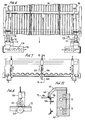
- Fig. 1 is an overall schematic side view of a multi-stage apparatus for thermo-forming low melt strength materials in accordance with the present invention;
- Fig. 1A is a fragmentary side sectional view of an exemplary thermo-formable sheet material useful in the present invention;
- Fig. 2 is an end view of the thermo-forming rollers;
- Fig. 3 is a side view of the forming rollers and the calibrator;
- Fig. 3A is a fragmentary detail in top plan view of a calibrator element;
- Fig. 4 is an end view of the calibrator taken along line 4-4 of Fig. 3;
- Figs. 5A and 5B are fragmentary end views of alternative forming rolls and an alternative calibrator, respectively;
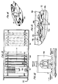
- Fig. 6 is a top plan view of an edge trimmer;
- Fig. 7 is an end sectional view of the trimmer taken along line 7-7 of Fig. 6;
- Fig. 8 is a side view of the trim knife taken along line 8-8 of Fig. 7;
- Fig. 9 is a side view of the primary drive;
- Fig. 10 is an end view of the primary drive;
- Fig. 11 is a top plan view of the oven and secondary drive;
- Fig. 12 is a sectional view of the secondary drive taken along line 12-12 of Fig. 11;
- Fig. 13 is a top plan view of the panel cutter;
- Fig. 14 is a side sectional view of the panel cutter taken along line 14-14 of Fig. 13;
- Fig. 15 is a fragmentary perspective of the clamping jaws in the panel cutter; and
- Fig. 16 is a fragmentary perspective of the panel cutting knife.
- A thermo-forming
apparatus 10 in accordance with the present invention as illustrated in Fig. 1. The apparatus is a multi-stage system for supplying, heating, thermo-forming, cooling and discharging corrugated sheet formed of a material which has low melt strength at forming temperatures. During heating and thermo-forming, the material is maintained at a selected uniform width to prevent lateral shrinkage. - The
apparatus 10 includes asupply stage 12,heater stage 14, a thermo-formingstage 16, acooling stage 18 and a trim/cut/stack ordischarge stage 20. A supply of thermo-formable sheet material 22 is fed from thefeed stage 12 through theheater stage 14, the thermo-formingstage 16, thecooling stage 18 and thedischarge stage 20 whereupon different operations are performed to producesized panels 24 cut to length and width. The material orsupply 22 is drawn through theapparatus 10 by means of aprimary drive 26 downstream of the thermo-formingstage 16. Asecondary drive 28 upstream of theprimary drive 26 laterally supports thesheet 22 and feeds it through theheater stage 14 and the thermo-formingstage 16. Optionally, the secondary drive may extend through at least a portion of the cooling stage located upstream of theprimary drive 26. - Clear corrugated sheet is useful for greenhouse applications. In one embodiment of the present invention, the raw material forming the
sheet 22 comprises a base layer of polycarbonateflat sheet 31 that is co-extruded with a UV stabilized cap layer 32. The thickness of thesheet 22 is dependent upon the application and the finished product thickness. Typically, the thickness for greenhouse applications is 0.033 inch. - The
sheet 22 is wound on one ormore supply spools 34 which typically contain between 8,000 and 10,000 feet ofsheet material 22. Thespools 34 are placed into anunwind stand 36 in thesupply stage 12. Although not shown, the spools may also be carried by movable carts into thesupply stage 12 in lieu of using a separate unwindstand 36. Thespools 34 are threaded over an idler 38 and under adancer roll 40 in aframe 42 which is retractably mounted in thesupply stage 12. An additional series of rollers including asecondary dancer roll 44 is provided to stabilize thesupply 22. As illustrated in Fig. 1, a pair of unwind stands 36 andmovable frames 42 are provided so as to allow for a resupply of thesheet material 22 as one or theother spool 34 is exhausted. - The
sheet material 22 is supplied in a selected width, e.g., about 59 inches, measured at its marginal edges 46 (Fig. 11).Secondary drive 28 in the form of achain drive 50 receives thesheet 22 upstream of thesupply stage 12. The chain drive comprises a pair of laterally disposed endless chains 52 (Fig. 11) mounted laterally of thesheet 22 and inboard of itsmarginal edges 46. Thechains 52 extend lengthwise of theapparatus 10 upstream of theheater stage 14 and downstream of at least the thermo-formingstage 16. Thechains 52 are formed of individual links 54 which carry outwardly radially extending pins 56 (Fig. 11). Thechains 52 are mounted onsprockets 58 for endless rotation inchain drive frame 60 as shown, for example, in Fig. 12. Acover 62 may be fixed or hinged to thechain drive frame 60. Thecover 62 has a slottedportion 64 which is adapted to receive thepins 56 for motion in a downstream direction. A channel 66 is formed between thecover 62 and theframe 60. - The
supply 22 is threaded into the channel 66 near itsmarginal edges 46. Thepins 56 puncture and laterally support thesheet 22 inboard of itsmarginal edge 46. The channel 66 is elongated laterally so as to tolerate variations in the width of thesheet material 22. Thechain 52 andsprockets 58 which are driven by a motor or a chain drive (not shown) pulls thesheet 22 in the upstream direction through theheater stage 14 and thermo-formingstage 16. At the downstream end of thechain drive 50 near the thermo-formingstage 16, thepins 56 anddownstream sprockets 58 disengage from thesheet 22 thereby releasing the lateral support. -
Cooling channels 70 are provided in theframe 60 to maintain the temperature of thechain drive 50 at a desired level which is below the melting point or glass transition temperature of thesheet 22 so as to permit the pins to continuously support the sheet through the heating and thermo-formingstages - The
primary drive 26, as illustrated in Figs. 9 and 10, engages thesheet 22 downstream of the thermo-formingstage 16 for drawing it therethrough at a selected draw rate. In the embodiment illustrated theprimary drive 26 comprises a pair of spaced apartupper drive rollers 80 and power drivenbackup rollers 82 mounted in a frame 84. Thebackup rollers 82 are formed of a metal core 86 which carries aresilient sleeve 88.Primary drive rollers 80 engage the thermo-formedsheet material 22 from the top side and drive thesheet 22 in the upstream direction. Thedrive rollers 80 generally comprise a metal core orshaft member 90 carrying a plurality of spaced apartannular drive wheels 92 each of which has a resilient annular sleeve orcover 94. In operation, thedrive rollers 80 andbackup rollers 82 engage thesheet material 22 therebetween, for drawingsheet 22 through the apparatus. When thesheet material 22 has been thermo-formed with corrugations, the spaced apartannular drive rollers 80 engage thesheet material 22 at a nip formed with the power drivenbackup rollers 82 between the corrugations without damaging the structure or surface of the thermo-formed material. - The heater stage 14 (Figs 1 and 11) generally comprises an
enclosed housing 100 having an open inlet orupstream end 102 and a downstream oroutlet end 104. Disposed within thehousing 100 are a plurality of separately temperaturecontrol heater units sheet material 22 is carried through thehousing 100 from theinlet 102 to theoutlet 104 past each of theheater units heating stage 14 is gradually increased between theinlet 102 and theoutlet 104 to bring the temperature of thesheet material 22 just above glass transition temperature Tg at theoutlet 104. Theheater unit 106 initially raises the temperature of thesheet material 22 from room temperature to about Tg/2 Of course, different materials may have different glass transition temperatures and may require variations in the temperature build up. In the embodiment illustrated for the polycarbonate sheet, theinitial heater unit 106 in Zone I operates at about 200°F. Theheating unit 110 in Zone III near theoutlet 104 of thehousing 100 operates at some temperature above Tg in which thesheet material 22 is thermo-formable but which retains its integrity within the apparatus. For the exemplarypolycarbonate sheet material 22 discussed the temperature of the final heating Zone III is about 380°F. - The intermediate heat Zone II is operated at a temperature or temperatures near Tg of the
sheet 22. In the arrangement illustrated, the temperature of the intermediate heating Zone II ranges from above 1.03 Tg to about 0.9 Tg. In the arrangement illustrated, the temperature of theintermediate heater 108 is highest near themarginal edges 46, e.g., about 1 to 3 percent higher than Tg to about 0.9 Tg near the center of thesheet 22. The reason for the grading of the temperature across thesheet 22 is to compensate for heat losses which may occur near thelateral margins 112 of each of theheating elements sheet 22. - The thermo-forming
stage 16 is located in close proximity to theoutlet 104 of theheating stage 14. Thus, thesheet material 22 is carried into the thermo-formingstage 16 at or above Tg its thermo-forming temperature. Of course the thermo-formingstage 16 may be spaced from theheating stage 14 if desired. However, it has been found that closely spacing the respective heating and thermo-formingregions sheet material 22. - The thermo-forming
stage 16 comprises a pair of interdigitated temperature controlled, power driven thermo-formingrollers sheet material 22 therebetween from theoutlet 104 of theheating stage 14. The thermo-formingrollers - A
calibrator 122 is closely coupled to the downstream side of the thermo-formingrollers rollers sheet material 22 above the thermo-forming temperature and thecalibrator 122 captures and maintains the shape of the thermo-formed material as it cools below the glass transition temperature. - As illustrated in Fig. 2, the
rollers respective core roller 124 and 125 and a plurality of axially spaced annular formingrollers 126 and 127. Therollers core 124 and 125 and are arranged so that the annular formingrollers 126 and 127 are interdigitated as shown. Therollers 126 and 127 are each removable from itscore 124 and 125. Thesheet material 22 is captured between the formingrollers peaks 128 andtroughs 130 corresponding to the deformations attributable to the respective lower and upper annular formingrollers 126 and 127. - The
core rollers 124 and 125 may include internal passages (not shown) for receiving a temperature controlled supply of fluid, (e.g., heated water) therethrough. The heated water maintains the thermo-formingrollers rollers secondary drive 28. - The forming rollers 126 may be readily removed from the
core rollers 124 and 125 and alternative rollers may be substituted having different profiles to change the shape of the corrugations. For example, different height and width and curative profiles may be readily achieved. - As illustrated in Fig. 3, the
calibrator 122 is located on the downstream side of the formingmembers calibrator 122 comprises a pair of spaced apart interdigitatedmembers upper members 140 engage thevalleys 130 of the thermo-formedsheet material 22 and thelower members 142 engage thepeaks 128 of the deformed sheet whereby the corrugated shape is maintained as thesheet material 22 is drawn therethrough. - As illustrated in Fig. 3, the respective upper and
lower calibrator members upstream end 144 and adownstream end 146. Theupstream end 144 is shaped so as to closely conform with the shape of the respective formingrollers 118 and 120 (Fig 3A). That is, the upstream ends 144 of the calibratingmembers rollers sheet material 22 to be readily captured as soon as possible after it leaves the formingrollers calibrator 122 is spaced from the formingrollers sheet material 22 falls below the forming temperature, thecalibrator 122 may temporarily deform it, but the desired deformation will not be maintained after the sheet material leaves thedownstream end 146. Thus, in accordance with the present invention, the purpose of the formingrollers valleys calibrator 122 is to hold and maintain the desired shape of the corrugated sheet while allowing the material to cool below the glass transition temperature whereby the deformations will set at the desired shape. The close proximity of thecalibrator elements rollers - The
calibration members cooling channel 143 which extend from near theinlet 144 to near theoutlet 146. The coolingchannels 143 receive a cooling fluid, (e.g., water) whereby the temperature of thecalibrator 122 is maintained at an appropriate temperature for assuring proper thermo-forming of the sheet. - The
calibration members intermediate spacers 145 which match the spacing of the annular formingrollers 126 and 127. The shape and space of thecalibrator members rollers rolls calibrator 122 may be readily varied as illustrated by the alternative forming rolls 118' and 120' and calibrator structures 122' shown in Figs. 5A and 5B, respectively. - As the sheet material is carried through the thermo-forming
stage 16, thechain drive 50 maintains lateral tension on thesheet material 22 to thereby maintain its lateral width while under deformation. As thedeformed sheet material 22 leaves the thermo-formingstage 16, thechain drive 50 disengages from the material as illustrated. - Cooling
stage 18, downstream of the thermo-formingstage 16, provides forced cooling for the sheet material 22 (Fig. 1). The cooling stage may comprise a pair ofplatens 150 disposed in confronting relation at opposite sides of thesheet material 22. Theplatens 150 may be formed withflow channels 152 coupled to a source of cooling fluid, (e.g., water). The coolingstage 18 may also include one or moresupplemental air blowers 156. In the embodiment illustrated, the cooledplatens 150 are located immediately downstream of the thermo-formingstage 16 and theblower 156 is downstream of theprimary drive 26. - In the primary drive 26 (Figs. 9 and 10), the
rollers 80 including theannular wheels 92 engage thevalleys 130 of thedeformed sheet 22 and the cylindrical back uproller 82 engages the under side of the sheet opposite theprimary rollers 80. As illustrated, both the back uprollers 82 and theannular drive wheels 92 have 4corresponding rubber sleeves drive backup rollers 82 impart appropriate pulling force on thecorrugated sheet 22. Thesleeves sheet 22 atnips 93. This resilient gripping action prevents damage to the sheet by virtue of the engaging driving wheels. - As shown in Figs. 6, 7 and 8, the
discharge stage 20 may have a plurality of outboard width trimknives 160 each of which includes a cuttingroller 162 for engaging thesheet material 22 from the top side and a backing roller ormandrel 164 having a steppededge 166 with which thecutting blade 162 slits the sheet material lengthwise as it passes through thedischarge stage 20 in the downstream direction as illustrated. - Generally, at least two
width cutting knives 160 are provided which may be laterally adjusted with respect to thesheet material 22 for cutting various widths. If desired, one or more additional centrally locatedwidth cutting knives 161 the width may be employed to cut additional widths from the overall sheet. - The
outboard knives 160 act as edge cutters for trimmingexcess material 170 near themarginal edges 46 inboard of the sprocket holes 57. Theexcess material 170, trimmed from thesheet material 22, is directed intochopper units 172 downstream oftrim cutters 162. Thechoppers 172 are motor driven and discharge choppedsheet material 174 ontoconveyor belts 176 for recycling. - Referring to Figs. 13-16,
individual panels 24 are cut from the trimmedsheet material 22. Apanel cutter 180 is provided to cutpanels 24 for stacking in or transport from thedischarge stage 20. Thepanel cutter 180 includes upper andlower clamping members sheet member 22. The upper andlower clamping sheet 22. A reciprocal two edgedknife 190 rides in achannel 192 in theupper clamping member 184 and has adouble edge 191 which extends into aslot 193 in thelower member 186. Theknife 190 moves in either direction transversely of the formedsheet 22 cutting through each of the respective peaks andtroughs panel cutter 180 may be mounted on a cutting table 194 downstream of the coolingstage 18. The upper andlower clamping members sheet 22 allowing thecutter 180 to move downstream of the table 194. As thecutter 190 moves downstream, thereciprocal knife 190 entersslot 193 and is moved transversely to cut thesheet 22 forming the panels 24- Thereciprocal knife 190 remains at rest at one side or another of thechannel 192 and the clampingmembers cut panel 24. Thereafter thepanel cutter 180 moves upstream to again engage the formedsheet 22. Theknife 190 is then moved in the opposite direction to cut with the two-sided blade 191. Thepanel cutter 180, the clampingmembers knife 191 may be hydraulically actuated by air or electric motors or the like. - In order to provide for proper threading and for emergency termination of thermo-forming,
shear cutter 196 may be located upstream of thesupply stage 12 as shown in Fig. 1. Theshear cutter 196 has a pair ofblades sheet material 22. Theshear blades heater section 14. Additional shear cutters (not shown) may be provided at other locations as desired. - The various actuators in the system may be hydraulic or electrically operated. In one embodiment of the invention, the unwind stand 36 is hydraulically actuated. The
shear cutter 196 and thepanel cutter 180 in thedischarge stage 20, and the primary andsecondary drives - In accordance with the present invention, the
secondary drive 28 is operated at a speed which is a percentage of the drive speed of theprimary drive 26. Thesheet material 22 is thus maintained under tension as it is drawn through the thermo-formingstage 16. In the embodiment illustrated, thesecondary drive 26 operates at about 95 percent of the linear pull speed of theprimary drive 26. Different materials require suitable adjustments to the differential speed of between the respective primary andsecondary drive - In accordance with the invention, there has been provided a method for thermo-forming materials having low melt strength at the forming temperature including: laterally supporting the material prior to thermo-forming; heating the material up to a thermo-forming temperature near its glass transition temperature; thermo-forming the material above its glass transition temperature immediately after heating; calibrating the thermo-formed material by capturing it proximate the thermo-forming step whereby the calibration occurs above the glass transition temperature; and maintaining said deformation while cooling the material to below the glass transition temperature.
- The method also includes differentially driving the sheet material at a first driving speed subsequent the deformation which is higher than a second driving speed prior to thermo-deformation.
- While there has been described what at present are considered to be the preferred embodiments of the present invention, it will be readily apparent to those skilled in the art that various changes and modifications may be made therein without departing from the invention and it is intended in the appended claims to cover such changes and modifications as fall within the true spirit and scope of the invention.
Claims (30)
- Apparatus for continuously producing corrugated sheet from a supply of sheet material having low melt strength at forming temperatures comprising:
a supply for supplying the sheet material;
a carrier coupled to the supply for carrying the sheet material along a longitudinal path and transversely supporting the sheet material along the path for maintaining the sheet material at a selected width therewithin;
a heater in the path having a plurality of heating stages for receiving the sheet material therethrough and raising the temperature of the sheet material to its forming temperature; and
thermo-forming means including a pair of opposed interdigitated forming rollers transverse of the path for receiving the sheet material heated to its forming temperature therebetween and for forming corrugations in the heated sheet; and
a cooled calibrator being located in the path closely adjacent to the forming rollers and having a profiled inlet transverse to the path engaging the forming rollers in closely spaced conforming relation for capturing the corrugated sheet therein immediately after forming, said calibrator having a pair of opposed interdigitated profiled surfaces extending from the inlet along the path to an outlet for maintaining the corrugations in the sheet as the heated sheet cools below its forming temperature. - The apparatus of claim 1, further including primary drive means at the outlet of the calibrator for engaging the sheet material and drawing it from the calibrator at a selected rate.
- The apparatus of claim 2, further including secondary drive means for the carrier for transmitting the sheet material in a direction of travel from the supply to the forming rollers at a selected rate.
- The apparatus of claim 3, wherein the drive rate of the primary drive means is greater than the drive rate of the secondary drive means for imparting tension on the sheet material as it is drawn through the forming rollers and the calibrator.
- The apparatus of claim 2, wherein the primary drive means includes a pair of rollers at least one of which has a plurality of spaced apart annular drive members for engaging deformations in the sheet material from one side thereof and the other roller engages a sheet material opposite the annular drive members.
- The apparatus of claim 5, wherein the annular drive member and the backup roller each include a resilient cover for frictionally engaging opposite sides of the sheet and preventing damage thereto as the sheet is drawn through the apparatus.
- The apparatus of claim 1, further including means for trimming the corrugated sheet from the carrier to form corrugated sheet of a selected width.
- The apparatus of claim 1, further including means for cutting the corrugated sheet to selected lengths.
- The apparatus of claim 1, wherein the heater comprises a first heating zone for raising the temperature of the sheet from ambient gradually to a temperature near about one half the forming temperature.
- The apparatus of claim 1, wherein the heater comprises a second heating zone for raising the temperature of the sheet to near the forming temperature.
- The apparatus of claim 10, wherein the second heating zone has a temperature gradient being greater near marginal edges and lesser near the center of the sheet.
- The apparatus of claim 1, wherein the heater comprises a third heating zone for maintaining the temperature of the sheet at the forming temperature immediately prior to thermo-forming.
- The apparatus of claim 1, wherein the heater includes at least one heating zone having a temperature gradient being greater near marginal edges of the sheet than near the center of the sheet.
- The apparatus of claim 1, wherein the forming rollers each comprise a drive roller of a selected diameter and a plurality of annular forming rollers secured to the drive roller in a selected spaced apart relation therealong.
- The apparatus of claim 14, wherein the annular members are removably located on the drive roller.
- The apparatus of claim 14, wherein the annular members are uniformly spaced along the drive roller.
- The apparatus of claim 14, wherein a pair of the thermo-forming rollers are disposed so that the annular members of one roller are located axially between and in spaced relation with the annular members of the other roller.
- The apparatus of claim 14, wherein each annular member has a selected profile for forming a corresponding profile in the sheet material.
- The apparatus of claim 1, wherein the carrier comprises a pair of elongated endless members located laterally of the sheet material including spaced apart pin members carried on the endless members for perforating the sheet.
- The apparatus of claim 19, wherein the endless members include a pair of chains adapted for endless travel between the heater and the thermo-forming device.
- The apparatus of claim 20, wherein the chains further include a plurality of interconnected links and a plurality of pin members extending radially outward of the links for engaging and perforating the sheet material between the heater and the thermo-forming device.
- The apparatus of claim 1, wherein said calibrator comprises a plurality of elongated calibrating members each having a shaped surface for engaging the corrugated sheet, said surfaces disposed in interdigitated confronting relationship.
- The apparatus of claim 22, wherein the calibrating means further includes means in the form of a plurality of channels formed opposite the shaped surfaces for receiving a cooling fluid therethrough.
- The apparatus of claim 22, further including spacer means disposed between the calibrating members.
- The apparatus of claim 22, wherein first and second sets of calibrating members and spacers are located in opposite confronting relation for maintaining the thermo-formed corrugations in the sheet until the temperature of the sheet falls below the glass transition temperature.
- The apparatus of claim 1, wherein the calibrator means includes an inlet having a surface transverse to the sheet in closely conforming relationship with the forming rollers whereby the formed sheet is immediately captured in the calibrator subsequent to thermo-forming.
- The apparatus of claim 1, further including cooling means downstream of the calibration for cooling the thermo-formed sheet.
- The apparatus of claim 27, wherein the cooling means comprises a pair of fluid cooled platens disposed for receiving the sheet material therebetween.
- The apparatus of claim 27, wherein the cooling means comprises a blower.
- A method of continuously producing corrugated sheet from a supply of a material having low melt strength at the forming temperature comprising:
gradually heating the material to glass transition temperature;
thermo-forming the material immediately subsequent to heating and calibrating the material immediately subsequent to thermo-forming while simultaneously maintaining lateral tension on the sheet material during the heating, thermo-forming, and calibration steps.
Applications Claiming Priority (2)
| Application Number | Priority Date | Filing Date | Title |
|---|---|---|---|
| US07/960,489 US5340518A (en) | 1992-10-13 | 1992-10-13 | Method for corrugating sheet material |
| US960489 | 1992-10-13 |
Publications (2)
| Publication Number | Publication Date |
|---|---|
| EP0593236A1 true EP0593236A1 (en) | 1994-04-20 |
| EP0593236B1 EP0593236B1 (en) | 1997-01-08 |
Family
ID=25503233
Family Applications (1)
| Application Number | Title | Priority Date | Filing Date |
|---|---|---|---|
| EP93308065A Expired - Lifetime EP0593236B1 (en) | 1992-10-13 | 1993-10-11 | Method for corrugating sheet material |
Country Status (5)
| Country | Link |
|---|---|
| US (1) | US5340518A (en) |
| EP (1) | EP0593236B1 (en) |
| JP (1) | JP2644673B2 (en) |
| DE (1) | DE69307252T2 (en) |
| ES (1) | ES2097459T3 (en) |
Cited By (3)
| Publication number | Priority date | Publication date | Assignee | Title |
|---|---|---|---|---|
| WO1998032607A1 (en) * | 1997-01-23 | 1998-07-30 | B Plas Bursa Plastik Sanayi Ve Ticaret A.S. Demirtas Organize San. | Method to produce multi-layer plates, the relative plant and multi-layer plates obtained therewith |
| AU709063B2 (en) * | 1994-06-30 | 1999-08-19 | Hakle-Kimberly Deutschland Gmbh | An apparatus and process for producing a corrugated web and an absorbent article comprising a corrugated web |
| WO2018206490A1 (en) * | 2017-05-12 | 2018-11-15 | Philip Morris Products S.A. | Method of crimping a substantially continuous sheet of polymeric material |
Families Citing this family (9)
| Publication number | Priority date | Publication date | Assignee | Title |
|---|---|---|---|---|
| US5792487A (en) * | 1996-04-10 | 1998-08-11 | Witt Plastics Of Florida Inc. | Corrugated plastic wall panels |
| US20030033770A1 (en) * | 2001-08-20 | 2003-02-20 | Harel Kenneth N. | Drywall bead with knurled paper flaps |
| DE10256652A1 (en) * | 2002-12-03 | 2004-06-17 | WINKLER + DüNNEBIER AG | Process and assembly to manufacture hygiene incontinence products by differential speed presentation of moving webs to profiled surface under suck/blow action |
| US7513768B2 (en) * | 2003-09-18 | 2009-04-07 | United States Gypsum Company | Embedment roll device |
| US7182589B2 (en) * | 2003-09-18 | 2007-02-27 | United States Gypsum Company | Embedment device for fiber-enhanced slurry |
| US20070096366A1 (en) * | 2005-11-01 | 2007-05-03 | Schneider Josef S | Continuous 3-D fiber network formation |
| US20070254058A1 (en) * | 2006-05-01 | 2007-11-01 | Wade A B | Systems and methods for forming polymeric sheets |
| GB0813161D0 (en) * | 2008-07-18 | 2008-08-27 | Airbus Uk Ltd | Ramped stiffener and apparatus and method for forming the same |
| EP3656556B1 (en) * | 2018-11-21 | 2021-06-23 | Wellplast AB | A system and method for producing a multiple layer material |
Citations (10)
| Publication number | Priority date | Publication date | Assignee | Title |
|---|---|---|---|---|
| US2547880A (en) * | 1949-08-09 | 1951-04-03 | Leonard S Meyer | Method and apparatus for corrugating sheet material and forming laminated cellular units thereof |
| US3024496A (en) * | 1957-04-05 | 1962-03-13 | S Lavorazione Materie Plastisc | Method and apparatus for manufacturing corrugated thermoplastic sheets |
| GB891829A (en) * | 1960-04-05 | 1962-03-21 | Hermann Berstorff Maschb Ansta | Method of producing a continuous sheet of corrugated synthetic plastics material |
| FR1325861A (en) * | 1962-03-24 | 1963-05-03 | Gerland Soc Chimique | Method for corrugating sheets of plastic material and device for its implementation |
| CH372160A (en) * | 1959-04-14 | 1963-09-30 | C I M E M Di Fratelli Gadani | Press for the continuous production of corrugated reinforced plastic laminates in the direction of advancement of the laminate through the press |
| US3231654A (en) * | 1962-10-29 | 1966-01-25 | Johns Manville | Process of forming a reinforced resin panel |
| FR1544485A (en) * | 1966-11-17 | 1968-10-31 | Lavorazione Mat Plast | Device for longitudinally waving thermoplastic bands |
| US3887320A (en) * | 1973-04-13 | 1975-06-03 | Gen Plastics Corp | Apparatus for continuously forming plastic sheet and corrugating with vacuum pressure |
| FR2391842A1 (en) * | 1977-05-25 | 1978-12-22 | Gadani Carlo | ROTATING MOLD MACHINE FOR THE CONTINUOUS REALIZATION OF ELEMENTS IN REINFORCED THERMOSETTING RESINS OR THERMOPLASTIC LAMINATE |
| GB2092055A (en) * | 1980-12-29 | 1982-08-11 | Takiron Uk Ltd | Method of manufacturing corrugated sheets continuously and an apparatus for carrying out the method |
Family Cites Families (4)
| Publication number | Priority date | Publication date | Assignee | Title |
|---|---|---|---|---|
| US2547736A (en) * | 1947-08-08 | 1951-04-03 | Polaroid Corp | Process for stretching continuous materials such as sheeting and the like |
| US2547763A (en) * | 1947-11-12 | 1951-04-03 | Polaroid Corp | Method of stretching continuous materials such as sheeting and the like |
| GB805733A (en) * | 1954-04-09 | 1958-12-10 | Kalle & Co Ag | Process of transverse stretching of films of thermoplastic material |
| GB871329A (en) * | 1960-01-20 | 1961-06-28 | Akad Wissenschaften Ddr | Improvements in or relating to a method and an apparatus for the continuous manufacture of glass fibre reinforced synthetic resin webs |
-
1992
- 1992-10-13 US US07/960,489 patent/US5340518A/en not_active Expired - Lifetime
-
1993
- 1993-10-11 DE DE69307252T patent/DE69307252T2/en not_active Expired - Lifetime
- 1993-10-11 ES ES93308065T patent/ES2097459T3/en not_active Expired - Lifetime
- 1993-10-11 EP EP93308065A patent/EP0593236B1/en not_active Expired - Lifetime
- 1993-10-12 JP JP5253857A patent/JP2644673B2/en not_active Expired - Fee Related
Patent Citations (10)
| Publication number | Priority date | Publication date | Assignee | Title |
|---|---|---|---|---|
| US2547880A (en) * | 1949-08-09 | 1951-04-03 | Leonard S Meyer | Method and apparatus for corrugating sheet material and forming laminated cellular units thereof |
| US3024496A (en) * | 1957-04-05 | 1962-03-13 | S Lavorazione Materie Plastisc | Method and apparatus for manufacturing corrugated thermoplastic sheets |
| CH372160A (en) * | 1959-04-14 | 1963-09-30 | C I M E M Di Fratelli Gadani | Press for the continuous production of corrugated reinforced plastic laminates in the direction of advancement of the laminate through the press |
| GB891829A (en) * | 1960-04-05 | 1962-03-21 | Hermann Berstorff Maschb Ansta | Method of producing a continuous sheet of corrugated synthetic plastics material |
| FR1325861A (en) * | 1962-03-24 | 1963-05-03 | Gerland Soc Chimique | Method for corrugating sheets of plastic material and device for its implementation |
| US3231654A (en) * | 1962-10-29 | 1966-01-25 | Johns Manville | Process of forming a reinforced resin panel |
| FR1544485A (en) * | 1966-11-17 | 1968-10-31 | Lavorazione Mat Plast | Device for longitudinally waving thermoplastic bands |
| US3887320A (en) * | 1973-04-13 | 1975-06-03 | Gen Plastics Corp | Apparatus for continuously forming plastic sheet and corrugating with vacuum pressure |
| FR2391842A1 (en) * | 1977-05-25 | 1978-12-22 | Gadani Carlo | ROTATING MOLD MACHINE FOR THE CONTINUOUS REALIZATION OF ELEMENTS IN REINFORCED THERMOSETTING RESINS OR THERMOPLASTIC LAMINATE |
| GB2092055A (en) * | 1980-12-29 | 1982-08-11 | Takiron Uk Ltd | Method of manufacturing corrugated sheets continuously and an apparatus for carrying out the method |
Cited By (4)
| Publication number | Priority date | Publication date | Assignee | Title |
|---|---|---|---|---|
| AU709063B2 (en) * | 1994-06-30 | 1999-08-19 | Hakle-Kimberly Deutschland Gmbh | An apparatus and process for producing a corrugated web and an absorbent article comprising a corrugated web |
| WO1998032607A1 (en) * | 1997-01-23 | 1998-07-30 | B Plas Bursa Plastik Sanayi Ve Ticaret A.S. Demirtas Organize San. | Method to produce multi-layer plates, the relative plant and multi-layer plates obtained therewith |
| US6656594B1 (en) * | 1997-01-23 | 2003-12-02 | B. Plas Bursa Plastik Sanayi, Ve Ticaret A.S. Demitras Organize San. | Method to produce shaped multi-layer plates, the relative plant and shaped multi-layer plates obtained therewith |
| WO2018206490A1 (en) * | 2017-05-12 | 2018-11-15 | Philip Morris Products S.A. | Method of crimping a substantially continuous sheet of polymeric material |
Also Published As
| Publication number | Publication date |
|---|---|
| ES2097459T3 (en) | 1997-04-01 |
| DE69307252D1 (en) | 1997-02-20 |
| US5340518A (en) | 1994-08-23 |
| DE69307252T2 (en) | 1997-06-12 |
| JP2644673B2 (en) | 1997-08-25 |
| JPH06190914A (en) | 1994-07-12 |
| EP0593236B1 (en) | 1997-01-08 |
Similar Documents
| Publication | Publication Date | Title |
|---|---|---|
| US5340518A (en) | Method for corrugating sheet material | |
| CA1247320A (en) | Apparatus for the production of articles from a thermoplastic material and method of producing articles from a foil of thermoplastic material | |
| US4625372A (en) | Apparatus for the manufacture of biaxially stretched flat film | |
| US4115495A (en) | Processing extruded thermoplastic polymer | |
| CA2034359A1 (en) | Continuous plastics molding process and apparatus | |
| US4428720A (en) | Apparatus for producing polypropylene sheet | |
| CN113752510A (en) | Production process and intelligent production equipment of PLA degradable functional film | |
| KR20180035508A (en) | Bath towel fabric cutting machine | |
| US4495124A (en) | Method for producing polypropylene sheet | |
| CN114394475A (en) | Device and method for producing high-polymer waterproof coiled material | |
| KR101705486B1 (en) | Vinyl fabric manufacturing equipment | |
| IE53291B1 (en) | Method of producing an abrasion resistant sheet and apparatus for producing it | |
| US4307049A (en) | Method for the continuous formation of biaxially oriented thermoplastic materials and forming articles therefrom by intermittent forming means interfaced therewith | |
| CN210282838U (en) | Surplus limit retrieval and utilization device of calender | |
| JP2003300199A (en) | Trimming press method and device | |
| GB2333995A (en) | Applying protective plastics film to plastics panel sheet | |
| CN112045434B (en) | Production method of thin-skin annular piece for heat preservation | |
| US4416607A (en) | Apparatus for the continuous formation of biaxially oriented thermoplastic materials and forming articles therefrom by intermittent forming means interfaced therewith | |
| CN112045435B (en) | Thin-skin annular piece production equipment for heat preservation | |
| GB2092055A (en) | Method of manufacturing corrugated sheets continuously and an apparatus for carrying out the method | |
| JPH0515480Y2 (en) | ||
| EP0067238A2 (en) | Method and apparatus for the continuous formation of biaxially oriented thermoplastic materials and forming articles therefrom by intermittent forming means interfaced therewith | |
| GB2282985A (en) | Production of plastics sheet material | |
| IE74405B1 (en) | Production of plastics sheet material | |
| US3223766A (en) | Base film oscillation |
Legal Events
| Date | Code | Title | Description |
|---|---|---|---|
| PUAI | Public reference made under article 153(3) epc to a published international application that has entered the european phase |
Free format text: ORIGINAL CODE: 0009012 |
|
| AK | Designated contracting states |
Kind code of ref document: A1 Designated state(s): DE ES FR GB IT NL |
|
| 17P | Request for examination filed |
Effective date: 19941020 |
|
| 17Q | First examination report despatched |
Effective date: 19951128 |
|
| GRAG | Despatch of communication of intention to grant |
Free format text: ORIGINAL CODE: EPIDOS AGRA |
|
| GRAH | Despatch of communication of intention to grant a patent |
Free format text: ORIGINAL CODE: EPIDOS IGRA |
|
| GRAH | Despatch of communication of intention to grant a patent |
Free format text: ORIGINAL CODE: EPIDOS IGRA |
|
| GRAA | (expected) grant |
Free format text: ORIGINAL CODE: 0009210 |
|
| AK | Designated contracting states |
Kind code of ref document: B1 Designated state(s): DE ES FR GB IT NL |
|
| ET | Fr: translation filed | ||
| REF | Corresponds to: |
Ref document number: 69307252 Country of ref document: DE Date of ref document: 19970220 |
|
| ITF | It: translation for a ep patent filed |
Owner name: 0414;34MIFSAIC BREVETTI S.R.L. |
|
| REG | Reference to a national code |
Ref country code: ES Ref legal event code: FG2A Ref document number: 2097459 Country of ref document: ES Kind code of ref document: T3 |
|
| PLBE | No opposition filed within time limit |
Free format text: ORIGINAL CODE: 0009261 |
|
| STAA | Information on the status of an ep patent application or granted ep patent |
Free format text: STATUS: NO OPPOSITION FILED WITHIN TIME LIMIT |
|
| 26N | No opposition filed | ||
| REG | Reference to a national code |
Ref country code: GB Ref legal event code: IF02 |
|
| PG25 | Lapsed in a contracting state [announced via postgrant information from national office to epo] |
Ref country code: IT Free format text: LAPSE BECAUSE OF NON-PAYMENT OF DUE FEES Effective date: 20051011 |
|
| PGFP | Annual fee paid to national office [announced via postgrant information from national office to epo] |
Ref country code: NL Payment date: 20071024 Year of fee payment: 15 Ref country code: ES Payment date: 20071026 Year of fee payment: 15 |
|
| REG | Reference to a national code |
Ref country code: GB Ref legal event code: 732E |
|
| REG | Reference to a national code |
Ref country code: FR Ref legal event code: TP |
|
| NLS | Nl: assignments of ep-patents |
Owner name: SABIC INNOVATIVE PLASTICS IP B.V. Effective date: 20081023 |
|
| NLV4 | Nl: lapsed or anulled due to non-payment of the annual fee |
Effective date: 20090501 |
|
| PG25 | Lapsed in a contracting state [announced via postgrant information from national office to epo] |
Ref country code: NL Free format text: LAPSE BECAUSE OF NON-PAYMENT OF DUE FEES Effective date: 20090501 |
|
| REG | Reference to a national code |
Ref country code: ES Ref legal event code: FD2A Effective date: 20081013 |
|
| PG25 | Lapsed in a contracting state [announced via postgrant information from national office to epo] |
Ref country code: ES Free format text: LAPSE BECAUSE OF NON-PAYMENT OF DUE FEES Effective date: 20081013 |
|
| PGFP | Annual fee paid to national office [announced via postgrant information from national office to epo] |
Ref country code: FR Payment date: 20101020 Year of fee payment: 18 |
|
| PGFP | Annual fee paid to national office [announced via postgrant information from national office to epo] |
Ref country code: DE Payment date: 20101006 Year of fee payment: 18 |
|
| PGFP | Annual fee paid to national office [announced via postgrant information from national office to epo] |
Ref country code: GB Payment date: 20101006 Year of fee payment: 18 |
|
| GBPC | Gb: european patent ceased through non-payment of renewal fee |
Effective date: 20111011 |
|
| REG | Reference to a national code |
Ref country code: FR Ref legal event code: ST Effective date: 20120629 |
|
| PG25 | Lapsed in a contracting state [announced via postgrant information from national office to epo] |
Ref country code: DE Free format text: LAPSE BECAUSE OF NON-PAYMENT OF DUE FEES Effective date: 20120501 |
|
| REG | Reference to a national code |
Ref country code: DE Ref legal event code: R119 Ref document number: 69307252 Country of ref document: DE Effective date: 20120501 |
|
| PG25 | Lapsed in a contracting state [announced via postgrant information from national office to epo] |
Ref country code: FR Free format text: LAPSE BECAUSE OF NON-PAYMENT OF DUE FEES Effective date: 20111102 Ref country code: GB Free format text: LAPSE BECAUSE OF NON-PAYMENT OF DUE FEES Effective date: 20111011 |