EP0593169A1 - Swing out armrest cupholder - Google Patents
Swing out armrest cupholder Download PDFInfo
- Publication number
- EP0593169A1 EP0593169A1 EP19930307519 EP93307519A EP0593169A1 EP 0593169 A1 EP0593169 A1 EP 0593169A1 EP 19930307519 EP19930307519 EP 19930307519 EP 93307519 A EP93307519 A EP 93307519A EP 0593169 A1 EP0593169 A1 EP 0593169A1
- Authority
- EP
- European Patent Office
- Prior art keywords
- container holder
- housing means
- assembly
- container
- cavity
- Prior art date
- Legal status (The legal status is an assumption and is not a legal conclusion. Google has not performed a legal analysis and makes no representation as to the accuracy of the status listed.)
- Granted
Links
Images
Classifications
-
- B—PERFORMING OPERATIONS; TRANSPORTING
- B60—VEHICLES IN GENERAL
- B60N—SEATS SPECIALLY ADAPTED FOR VEHICLES; VEHICLE PASSENGER ACCOMMODATION NOT OTHERWISE PROVIDED FOR
- B60N3/00—Arrangements or adaptations of other passenger fittings, not otherwise provided for
- B60N3/10—Arrangements or adaptations of other passenger fittings, not otherwise provided for of receptacles for food or beverages, e.g. refrigerated
- B60N3/102—Arrangements or adaptations of other passenger fittings, not otherwise provided for of receptacles for food or beverages, e.g. refrigerated storable or foldable in a non-use position
-
- B—PERFORMING OPERATIONS; TRANSPORTING
- B60—VEHICLES IN GENERAL
- B60N—SEATS SPECIALLY ADAPTED FOR VEHICLES; VEHICLE PASSENGER ACCOMMODATION NOT OTHERWISE PROVIDED FOR
- B60N2/00—Seats specially adapted for vehicles; Arrangement or mounting of seats in vehicles
- B60N2/75—Arm-rests
- B60N2/79—Adaptations for additional use of the arm-rests
- B60N2/793—Adaptations for additional use of the arm-rests for use as storage compartments
Definitions
- the invention relates to container holders for vehicles, and more particularly toward an armrest or console containing such container holders.
- cupholders or container holders utilized for supporting cups, cans or other beverage containers in vehicles which are selectively accessible to the vehicle passengers or occupants.
- Many of these container holders have been stored in armrest assemblies in the vehicles. Examples of such holders include United States Patent Number 4,943,111, issued July 24, 1990 in the name of VanderLaan and United States Patent Number 4,818,017, issued April 4, 1989 in the name of Dykstra et al.
- Both patents relate to cupholders which are stored in armrests in the vehicle. A full lid or cover on the armrest is raised and a cupholder mechanism is removed from internal the armrest and secured outwardly of the armrest. The lid of the armrest may be closed with the cupholder extending from the armrest.
- the problem with these types of holders is the difficulty of accessing the holder, i.e., the user must maneuver several components to properly position the cupholder to receive a cup or container.
- the invention is an assembly for supporting containers of the passenger in a vehicle.
- the assembly can be either an armrest assembly or a console assembly.
- the assembly can be either center or side mounted with respect to passengers, or it can be an installation within an instrument panel.
- the assembly comprises housing means for mounting to a vehicle and having an upper surface for supporting an arm of the passenger, a lower surface for placement adjacent a vehicle seat, side surfaces and a front surface interconnected to the upper, lower and side surfaces.
- the housing means includes storage means having a container holder therein pivotal between a closed position preventing access to the container holder and an open position allowing access to the container holder.
- the storage means includes a support shell for supporting the container and container holder in the open position with the support shell extending from the lower surface allowing access to the container holder, and pivotal to a closed position in which it forms the front surface of the assembly.
- the assembly can be either an armrest or a console unit.
- the invention also includes a first container holder operatively connected to the housing means for pivotal movement outwardly from the housing means from a cavity therein into an open position and pivotally retractable within the cavity when in its closed position, and a second container holder operatively connected to the first container holder for automatic axial movement into the cavity to a position aligned with an opening through the upper surface when the first container is in its open position and wherein the second container is axially moveable from the cavity to an internal space within the housing means as the first container is pivoted into the cavity thereby to prevent access to both container holders when in the closed position.
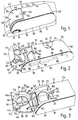
- FIG. 1 An assembly for supporting containers of a passenger in a vehicle is generally illustrated at 10 in Figures 1-3.
- the assembly 10 generally comprises housing means 12 forming an armrest or console which is secured to a vehicle for use by the passengers thereof.
- the illustrative embodiment of the subject invention shown in the Figures is of an armrest, though it is to be understood that the invention may be utilized in a console, instrument panel, etc.
- the housing means 12 includes a rigid plastic interior retainer 14 of a high strength plastic such as ABS.
- the retainer 14 has a foam-in-place covering layer 16 molded thereto.
- a suitable material is a polyurethane foam composition though other foam materials or soft padding is equally suitable for use with the present invention.
- a cover material 18 covers the foam 16 for aesthetics and wear properties.
- the plastic retainer 14 is configured in a generally rectangular form having a hollow cavity 20 and interior space 22.
- the housing means 12 may be formed by commonly known molding principles and while it is shown as a composite plastic construction other housing means, including injection molded thermoplastic materials or metal fabricated housing can be used.
- the housing means 12 includes an upper, flat surface 24 for supporting the arm of the passenger, side surfaces 25, 27 and a lower, flat surface 26 for placement adjacent the vehicle, i.e., resting on the seats 13 of the vehicle.
- a front surface 28 interconnects the upper surface 24 with the lower surface 26.
- the assembly 10 may be fixedly secured to vehicle seats 13 as an armrest assembly, or it may be part of a console or it can be part of an instrument panel housing all as commonly known in the art.
- the housing means 12 includes storage means 30 having a container holder 32 therein.
- the storage means 30 pivots between a closed position ( Figure 1) preventing access to the container holder 32, through a partially open position ( Figure 2), and to an open position ( Figure 3) allowing access to the container holder 32.
- the storage means 30 includes a support shell 34 for supporting the container and container holder 32 in the closed position, and for forming the front surface 28 and a portion of the upper surface 24 in the closed position.
- the storage means 30 pivots to the open position with the support shell 34 extending from the lower surface 26 allowing access to the container holder 32.
- the longitudinal side walls 25, 27 and a rear 40 form the remainder of the housing means 12 between the upper and lower surfaces 24, 26.
- the support shell 34 includes a base 35 comprising the front surface 28.
- the surface 28 has a bend 42 angling to a flange 44 forming a portion of and aligned with the upper surface 24.
- the upper surface 24 of the assembly 10 continues along the flange 44, and angles around the bend 42 to the base 35 of the front face side 36.
- the base 35 is pivotally connected to the lower surface 26 of the housing means 12.
- the flange 44 is spaced above and forward of an opening 45 into the cavity 20 through the upper surface 24.
- the container holder 32 includes a rigid plastic molded retainer 46 which is molded with the base 35, bend 42, and flange 44.
- the plastic retainer 46 includes a retainer cavity 48 formed by a cylindrical support walls 50 extending from the base 35 toward the housing cavity 20 in the closed position.
- the retainer cavity 48 has a bottom surface at the base 35.
- the retainer 46 on the inner surface of the upper flange 44 is shaped at 46a to form a portion of the cylindrical support walls 50.
- the cylindrical support walls 50 include a pair of notches 54 longitudinally therethrough on opposite sides across the cavity 48 to allow clearance for handles of a container to extend through.
- the support shell 34 is connected to the remainder of the housing means 12 between the base 35 and the lower surface 26 by a hinge 60.
- the hinge 60 allows the storage means 30 to pivot to the closed position and to the open position while maintaining and supporting same in a horizontal position with the lower surface 26.
- the hinge 60 may be of the type commonly known in the art, i.e., used for glove compartments.
- Latch means 64 is operatively connected between the storage means 30 and the remainder of the housing means 12.
- the latch means 64 may be of the releasible latch type that releases upon depression.
- the latch means 64 can be a manual lifting type of door tab, i.e., a magnetic latch.
- the latch means 64 includes an actuating member 65 secured to the upper surface 24 adjacent the opening 45.
- the actuating member 65 engages a notch 66 in the inner surface of the flange 44 to maintain same in the closed position. Depression of the actuating member 65 disengages it from the notch 66 allowing the storage means 30 to open.
- the storage means 30 also includes pivot control means 70 for biasing the storage means 30 in the open position whereby upon release of the latch means 64, the storage means 30 pivots from the closed position to the open position.
- the control means 70 includes a spring loaded and dampened tracking mechanism for controlling movement of the pivoting motion.
- the mechanism 70 is of the type parallel link tracking mechanism.
- the assembly 10 also contains a second container holder 80 slideably retained within the interior 22 of the housing 12 inboard of the cavity 20.
- the container holder 80 is pulled into alignment with cavity 22 for providing access to the second container holder 80 upon opening of the storage means 30.
- the second container holder 80 comprises a rigid plastic molded member 82 of a generally rectangular, plate shape, with a cylindrical opening 84 formed therein to receive a beverage container.
- a pair of tabs 88 extend outwardly from opposing sides of the member 82 for engaging an inner surface groove or track 86 in the inner surface 38 of side walls 25, 27 of the housing 12.
- the pair of opposing longitudinal grooves or tracks 86 receive the tabs 88 for slideably guiding the member 82 therein.
- the assembly 10 includes drive means 90 operatively connecting between the first container holder 32 and the second container holder 80 for sliding the second container holder 80 outwardly and providing access thereto upon pivotal movement of the storage means 30 to the open position.
- the drive means 90 comprises a pair of parallel linkage arms 90 pivotally connected between the sides of the container holders 32, 80, e.g., the arms 92 each extend between the holders 32, 80. Therefore, the linkage arms 90 will retain the holders 32, 80 at a predetermined spacing.
- the second container holder 80 is located fully within the hollow housing means 12 and the first container holder 32 is pivoted on a side or vertical position.
- the base portion 34 Upon opening of the storage means 30, the base portion 34 will pivot outwardly thereby pivoting the first container holder 32 to the horizontal position allowing access thereto.
- the linkage means 90 slide the second container holder 80 outwardly exposing the container cavity 84 in the opening 45 provided by the opened storage means 30.
- pivotal movement of the storage means 30 will cause the arms 90 to push the second holder 80 into the cavity 22.
- the assembly 10 may include illumination means 96 ( Figure 2), generally a soft glow light, connected within the cavity 20 and interior space 22 for illuminating the holders 32, 80 when in the open position.
- illumination means 96 Figure 2
- a contact switch 98 connected between the second holder 80 and the housing 12 senses opening of the storage means 30 to cause power and illumination of the light 96, and to discontinue power and illumination thereof in the closed position.
- the switch 98 interconnects a power line from the vehicle battery to the light 96.
Abstract
Description
- The invention relates to container holders for vehicles, and more particularly toward an armrest or console containing such container holders.
- There are a variety of cupholders or container holders utilized for supporting cups, cans or other beverage containers in vehicles which are selectively accessible to the vehicle passengers or occupants. Many of these container holders have been stored in armrest assemblies in the vehicles. Examples of such holders include United States Patent Number 4,943,111, issued July 24, 1990 in the name of VanderLaan and United States Patent Number 4,818,017, issued April 4, 1989 in the name of Dykstra et al. Both patents relate to cupholders which are stored in armrests in the vehicle. A full lid or cover on the armrest is raised and a cupholder mechanism is removed from internal the armrest and secured outwardly of the armrest. The lid of the armrest may be closed with the cupholder extending from the armrest. The problem with these types of holders is the difficulty of accessing the holder, i.e., the user must maneuver several components to properly position the cupholder to receive a cup or container.
- United States Patent Number 4,040,659, issued August 9, 1977 in the name of Arnold discloses a food tray and a cupholder combination for automobiles which slides out from within the armrest and from the front face thereof. The problem with this holder is that it requires substantial lateral space in front of armrest for extension and full deployment of a pair of cupholders and trays.
- The invention is an assembly for supporting containers of the passenger in a vehicle. The assembly can be either an armrest assembly or a console assembly. The assembly can be either center or side mounted with respect to passengers, or it can be an installation within an instrument panel. The assembly comprises housing means for mounting to a vehicle and having an upper surface for supporting an arm of the passenger, a lower surface for placement adjacent a vehicle seat, side surfaces and a front surface interconnected to the upper, lower and side surfaces. The housing means includes storage means having a container holder therein pivotal between a closed position preventing access to the container holder and an open position allowing access to the container holder. The storage means includes a support shell for supporting the container and container holder in the open position with the support shell extending from the lower surface allowing access to the container holder, and pivotal to a closed position in which it forms the front surface of the assembly. The assembly can be either an armrest or a console unit.
- The invention also includes a first container holder operatively connected to the housing means for pivotal movement outwardly from the housing means from a cavity therein into an open position and pivotally retractable within the cavity when in its closed position, and a second container holder operatively connected to the first container holder for automatic axial movement into the cavity to a position aligned with an opening through the upper surface when the first container is in its open position and wherein the second container is axially moveable from the cavity to an internal space within the housing means as the first container is pivoted into the cavity thereby to prevent access to both container holders when in the closed position.
- Advantages of the present invention will be readily appreciated as the same becomes better understood by reference to the following detailed description when considered in connection with the accompanying drawings wherein:
- Figure 1 is a partially cut away perspective view of the subject invention in the closed position and disposed downwardly on the seat of a motor vehicle;
- Figure 2 is a partially cut away perspective view of the subject invention in a partially open position; and
- Figure 3 is a partially cut away perspective view of the subject invention in a fully open position.
- An assembly for supporting containers of a passenger in a vehicle is generally illustrated at 10 in Figures 1-3. The
assembly 10 generally comprises housing means 12 forming an armrest or console which is secured to a vehicle for use by the passengers thereof. The illustrative embodiment of the subject invention shown in the Figures is of an armrest, though it is to be understood that the invention may be utilized in a console, instrument panel, etc. - The housing means 12 includes a rigid
plastic interior retainer 14 of a high strength plastic such as ABS. Theretainer 14 has a foam-in-place covering layer 16 molded thereto. A suitable material is a polyurethane foam composition though other foam materials or soft padding is equally suitable for use with the present invention. Acover material 18 covers thefoam 16 for aesthetics and wear properties. Theplastic retainer 14 is configured in a generally rectangular form having ahollow cavity 20 andinterior space 22. The housing means 12 may be formed by commonly known molding principles and while it is shown as a composite plastic construction other housing means, including injection molded thermoplastic materials or metal fabricated housing can be used. - The housing means 12 includes an upper,
flat surface 24 for supporting the arm of the passenger,side surfaces flat surface 26 for placement adjacent the vehicle, i.e., resting on the seats 13 of the vehicle. Afront surface 28 interconnects theupper surface 24 with thelower surface 26. Theassembly 10 may be fixedly secured to vehicle seats 13 as an armrest assembly, or it may be part of a console or it can be part of an instrument panel housing all as commonly known in the art. - The housing means 12 includes storage means 30 having a
container holder 32 therein. The storage means 30 pivots between a closed position (Figure 1) preventing access to thecontainer holder 32, through a partially open position (Figure 2), and to an open position (Figure 3) allowing access to thecontainer holder 32. The storage means 30 includes asupport shell 34 for supporting the container andcontainer holder 32 in the closed position, and for forming thefront surface 28 and a portion of theupper surface 24 in the closed position. The storage means 30 pivots to the open position with thesupport shell 34 extending from thelower surface 26 allowing access to thecontainer holder 32. - The
longitudinal side walls lower surfaces - The
support shell 34 includes abase 35 comprising thefront surface 28. Thesurface 28 has abend 42 angling to aflange 44 forming a portion of and aligned with theupper surface 24. In the closed position, theupper surface 24 of theassembly 10 continues along theflange 44, and angles around thebend 42 to thebase 35 of thefront face side 36. Thebase 35 is pivotally connected to thelower surface 26 of the housing means 12. In the open position, theflange 44 is spaced above and forward of anopening 45 into thecavity 20 through theupper surface 24. - The
container holder 32 includes a rigid plastic moldedretainer 46 which is molded with thebase 35,bend 42, andflange 44. Theplastic retainer 46 includes aretainer cavity 48 formed by a cylindrical support walls 50 extending from thebase 35 toward thehousing cavity 20 in the closed position. Theretainer cavity 48 has a bottom surface at thebase 35. Theretainer 46 on the inner surface of theupper flange 44 is shaped at 46a to form a portion of the cylindrical support walls 50. The cylindrical support walls 50 include a pair ofnotches 54 longitudinally therethrough on opposite sides across thecavity 48 to allow clearance for handles of a container to extend through. - The
support shell 34 is connected to the remainder of the housing means 12 between thebase 35 and thelower surface 26 by ahinge 60. Thehinge 60 allows the storage means 30 to pivot to the closed position and to the open position while maintaining and supporting same in a horizontal position with thelower surface 26. Thehinge 60 may be of the type commonly known in the art, i.e., used for glove compartments. - Latch means 64 is operatively connected between the storage means 30 and the remainder of the housing means 12. The latch means 64 may be of the releasible latch type that releases upon depression. Alternatively, the latch means 64 can be a manual lifting type of door tab, i.e., a magnetic latch. The latch means 64 includes an actuating
member 65 secured to theupper surface 24 adjacent theopening 45. The actuatingmember 65 engages anotch 66 in the inner surface of theflange 44 to maintain same in the closed position. Depression of the actuatingmember 65 disengages it from thenotch 66 allowing the storage means 30 to open. - The storage means 30 also includes pivot control means 70 for biasing the storage means 30 in the open position whereby upon release of the latch means 64, the storage means 30 pivots from the closed position to the open position. The control means 70 includes a spring loaded and dampened tracking mechanism for controlling movement of the pivoting motion. The
mechanism 70 is of the type parallel link tracking mechanism. - The
assembly 10 also contains asecond container holder 80 slideably retained within theinterior 22 of thehousing 12 inboard of thecavity 20. Thecontainer holder 80 is pulled into alignment withcavity 22 for providing access to thesecond container holder 80 upon opening of the storage means 30. Thesecond container holder 80 comprises a rigid plastic moldedmember 82 of a generally rectangular, plate shape, with acylindrical opening 84 formed therein to receive a beverage container. A pair oftabs 88 extend outwardly from opposing sides of themember 82 for engaging an inner surface groove ortrack 86 in theinner surface 38 ofside walls housing 12. The pair of opposing longitudinal grooves or tracks 86 receive thetabs 88 for slideably guiding themember 82 therein. - The
assembly 10 includes drive means 90 operatively connecting between thefirst container holder 32 and thesecond container holder 80 for sliding thesecond container holder 80 outwardly and providing access thereto upon pivotal movement of the storage means 30 to the open position. The drive means 90 comprises a pair ofparallel linkage arms 90 pivotally connected between the sides of thecontainer holders holders linkage arms 90 will retain theholders second container holder 80 is located fully within the hollow housing means 12 and thefirst container holder 32 is pivoted on a side or vertical position. Upon opening of the storage means 30, thebase portion 34 will pivot outwardly thereby pivoting thefirst container holder 32 to the horizontal position allowing access thereto. Upon this movement, the linkage means 90 slide thesecond container holder 80 outwardly exposing thecontainer cavity 84 in theopening 45 provided by the opened storage means 30. During closing, pivotal movement of the storage means 30 will cause thearms 90 to push thesecond holder 80 into thecavity 22. - Optionally, the
assembly 10 may include illumination means 96 (Figure 2), generally a soft glow light, connected within thecavity 20 andinterior space 22 for illuminating theholders contact switch 98 connected between thesecond holder 80 and thehousing 12 senses opening of the storage means 30 to cause power and illumination of the light 96, and to discontinue power and illumination thereof in the closed position. Theswitch 98 interconnects a power line from the vehicle battery to the light 96. - The invention has been described in an illustrative manner, and it is to be understood that the terminology which has been used is intended to be in the nature of words of description rather than of limitation.
- Obviously, many modifications and variations of the present invention are possible in light of the above teachings. It is, therefore, to be understood that within the scope of the appended claims the invention may be practiced otherwise than as specifically described.
Claims (7)
- An assembly for supporting containers of the passenger in a vehicle, said assembly comprising:
housing means including a front side and a lower surface for mounting to a vehicle;
said housing means including storage means having a first container holder therein for pivoting between a closed position within said housing means preventing access to said container holder and an open position outwardly of said housing means allowing access to said container holder;
said storage means including a support shell for supporting the container and said container holder in its open position and for forming a portion of said front side when said first container holder is in said closed position; and means for pivotally connecting said support shell to said lower surface for providing swinging movement of said support shell for allowing access to said container holder. - An assembly as set forth in claim 1 wherein said housing means includes an interior space therein, and the assembly further includes a second container holder disposed in said interior space of said housing means and automatically slideably extendable in response to said first container holder moving to said open position for supporting an additional container.
- An assembly as set forth in claim 2,
said housing means including an upper surface for defining an armrest;
said support shell including an exterior surface having a bend therein forming a connection between said upper surface and said front side. - An assembly as set forth in claim 2 further including linkage arms interconnecting said first and second container holders for sliding said second container holder in response to said first container holder moving between said open and closed positions.
- An assembly for supporting containers of the passenger in a vehicle, said assembly comprising:
housing means for mounting to a vehicle and having an upper surface for supporting an arm of the passenger, a lower surface for placement adjacent the vehicle, a front side interconnecting said surfaces, and a cavity therein;
said housing means including storage means connected to said front face of said housing means and forming a portion of said upper surface for moving between an open position providing an opening to said cavity through said upper surface and for moving to a closed position preventing access to said cavity;
said storage means including a first container holder operatively connected to said housing means for extending outwardly from said housing means and out of said cavity in said open position and extending within said cavity in said closed position, and a second container holder operatively connected to said first container holder for automatically moving within said cavity to a position aligned with said opening supported by and within said housing means when in said open position and for moving into said cavity preventing access thereto when in said closed position. - An assembly as set forth in claim 5 further including linkage arms interconnecting said first and second container holders for sliding said second container holder in response to said first container holder moving between said open and closed positions.
- An assembly as set forth in claim 6 further including said storage means including a base for supporting the container and said container holder in the open position and for forming a portion of said front side in said closed position, and for pivoting to said open position with said base portion extending from said lower surface allowing access to said container holder.
Applications Claiming Priority (2)
| Application Number | Priority Date | Filing Date | Title |
|---|---|---|---|
| US07/960,540 US5248183A (en) | 1992-10-13 | 1992-10-13 | Swing out armrest cupholder |
| US960540 | 1992-10-13 |
Publications (2)
| Publication Number | Publication Date |
|---|---|
| EP0593169A1 true EP0593169A1 (en) | 1994-04-20 |
| EP0593169B1 EP0593169B1 (en) | 1997-01-02 |
Family
ID=25503304
Family Applications (1)
| Application Number | Title | Priority Date | Filing Date |
|---|---|---|---|
| EP19930307519 Expired - Lifetime EP0593169B1 (en) | 1992-10-13 | 1993-09-22 | Swing out armrest cupholder |
Country Status (11)
| Country | Link |
|---|---|
| US (1) | US5248183A (en) |
| EP (1) | EP0593169B1 (en) |
| JP (1) | JPH06191340A (en) |
| KR (1) | KR100322919B1 (en) |
| AU (1) | AU4866093A (en) |
| CA (1) | CA2106711A1 (en) |
| CZ (1) | CZ214293A3 (en) |
| DE (1) | DE69307087T2 (en) |
| ES (1) | ES2097990T3 (en) |
| MX (1) | MX9306319A (en) |
| PL (1) | PL300683A1 (en) |
Cited By (5)
| Publication number | Priority date | Publication date | Assignee | Title |
|---|---|---|---|---|
| DE4429515C1 (en) * | 1994-08-19 | 1995-11-16 | Fischer Artur Werke Gmbh | Device for holding two beverage containers in the center console of a motor vehicle |
| DE19724597C1 (en) * | 1997-06-11 | 1998-11-26 | Daimler Benz Ag | Central console for motor vehicle |
| EP1312501A3 (en) * | 2001-11-14 | 2004-05-26 | fischer automotive systems GmbH | Arrangement of container and cupholder for means of locomotion |
| DE102009012902A1 (en) | 2009-03-12 | 2010-09-16 | GM Global Technology Operations, Inc., Detroit | Console for a vehicle |
| DE102015210975A1 (en) * | 2015-06-15 | 2016-12-15 | Bos Gmbh & Co. Kg | Device for holding at least one container in a vehicle interior and pivotable armrest unit with such a device |
Families Citing this family (49)
| Publication number | Priority date | Publication date | Assignee | Title |
|---|---|---|---|---|
| US5330146A (en) * | 1993-12-07 | 1994-07-19 | Prince Corporation | Container holder |
| US5505516A (en) * | 1994-03-15 | 1996-04-09 | Prince Corporation | Compact container holder |
| DE4415732C2 (en) * | 1994-05-04 | 2000-10-26 | Johnson Contr Interiors Gmbh | Armrest between two seats of a motor vehicle arranged side by side |
| US5562331A (en) * | 1994-12-09 | 1996-10-08 | Prince Corporation | Storage compartment with cover |
| US5628486A (en) * | 1995-05-30 | 1997-05-13 | Summit Polymers | Concealable beverage container holder |
| DE19534840A1 (en) * | 1995-09-20 | 1997-03-27 | Happich Gmbh Gebr | Installation device |
| US5860630A (en) * | 1996-05-14 | 1999-01-19 | Freightliner Corporation | Beverage container holder for a vehicle |
| US5857633A (en) * | 1996-08-19 | 1999-01-12 | Toyota Technical Center U.S.A., Inc. | Cupholder with engaging rings |
| KR100212422B1 (en) * | 1996-12-30 | 1999-08-02 | 허봉 | Cupholder for a vehicle |
| GB2326395A (en) * | 1997-06-21 | 1998-12-23 | Rover Group | A container holder for a motor vehicle |
| FR2774638B1 (en) | 1998-02-09 | 2000-03-31 | Renault | RETRACTABLE OBJECT HOLDER FOR THE INTERIOR DESIGN OF A MOTOR VEHICLE |
| US6799705B1 (en) * | 1999-11-01 | 2004-10-05 | Jarek Lutoslawski | Cup holder closure and release apparatus |
| DE19953502A1 (en) * | 1999-11-06 | 2001-05-17 | Daimler Chrysler Ag | Container unit for vehicle has drawer with at least one container holder movable between retracted and extracted positions with actuating element fitted with illumination device |
| US6874667B2 (en) * | 1999-11-30 | 2005-04-05 | Johnson Controls Technology Company | Vehicle cargo management system |
| DE10007594A1 (en) * | 2000-02-18 | 2001-08-23 | Fischer Artur Werke Gmbh | Holder for a beverage container |
| US6550862B2 (en) | 2001-06-14 | 2003-04-22 | Cosco Management, Inc. | Juvenile vehicle seat cup holder |
| US6688571B1 (en) | 2001-10-12 | 2004-02-10 | Sunrise Medical Hhc Inc. | Adjustable joystick support and wheelchair therewith |
| US6997509B2 (en) * | 2001-10-19 | 2006-02-14 | Cosco Management, Inc. | Juvenile seat cup holder |
| US6547326B1 (en) * | 2001-11-01 | 2003-04-15 | Ford Global Technologies, Inc. | Automotive seat flip-out cupholder |
| US7066536B2 (en) * | 2002-02-11 | 2006-06-27 | Graco Children's Products Inc. | Child seat |
| DE20216675U1 (en) * | 2002-10-29 | 2003-03-13 | Trw Automotive Electron & Comp | Cup holder |
| US7264291B2 (en) * | 2004-09-28 | 2007-09-04 | Lear Corporation | Assembly for supporting an article in a vehicle |
| US7147259B2 (en) * | 2004-10-01 | 2006-12-12 | Lear Corporation | Console and object holder assembly for a vehicle |
| US7192070B2 (en) * | 2004-11-22 | 2007-03-20 | Lear Corporation | Vehicle console with armrest extension |
| CN2762964Y (en) * | 2005-01-10 | 2006-03-08 | 南京德朔实业有限公司 | Electric tool power supplied by battery |
| KR100680531B1 (en) * | 2005-10-11 | 2007-02-08 | 기아자동차주식회사 | Cup holder of seats in the vehicle |
| US20080142663A1 (en) * | 2006-12-15 | 2008-06-19 | Sabrena Wright | Devices and methods for supporting and protecting portable electronics |
| JP4986133B2 (en) * | 2007-02-13 | 2012-07-25 | 日本発條株式会社 | Cup holder |
| US20090015044A1 (en) * | 2007-07-09 | 2009-01-15 | Britax Child Safety, Inc. | Retractable cup holder assembly for child seat |
| DE102007059230A1 (en) * | 2007-12-07 | 2009-07-02 | F.S. Fehrer Automotive Gmbh | Central arm rest for motor vehicle, has cover adjusted between closing position and opening position, and storage compartment arranged in storage spaces by arrangement of cover in opening position and closing position, respectively |
| GB2458283A (en) * | 2008-03-12 | 2009-09-16 | Valtra Oy Ab | Vehicle armrest with stowable drivers interface |
| DE102008023214B4 (en) * | 2008-05-10 | 2018-01-18 | Ford Global Technologies, Llc | Interior trim part for a motor vehicle interior |
| US8322671B2 (en) * | 2009-10-28 | 2012-12-04 | Honda Motor Co., Ltd. | Tray mechanism with automatic beverage holding device |
| US8911011B2 (en) * | 2010-03-03 | 2014-12-16 | Lear Corporation | Armrest assembly having beverage holder |
| US9145075B2 (en) | 2010-09-28 | 2015-09-29 | Lear Corporation | Vehicle modular armrest |
| US8668258B2 (en) | 2011-01-26 | 2014-03-11 | Honda Motor Co., Ltd. | Arm rest |
| KR101251258B1 (en) * | 2011-11-03 | 2013-04-10 | 기아자동차주식회사 | Cup holder of console box for vehicle |
| DE102012224358A1 (en) * | 2012-12-24 | 2014-06-26 | Lufthansa Technik Ag | vehicle seat |
| US9327650B2 (en) * | 2014-07-30 | 2016-05-03 | Toyota Motor Engineering & Manufacturing North America, Inc. | Cup holder assembly with cantilevered support |
| DE102014013770A1 (en) * | 2014-09-17 | 2016-03-17 | Audi Ag | Equipment element for an interior of a motor vehicle |
| US9862296B2 (en) * | 2015-02-13 | 2018-01-09 | Ford Global Technologies, Llc | Cup holder system for a motor vehicle |
| CN106476663A (en) * | 2015-08-28 | 2017-03-08 | 福特环球技术公司 | Vehicle storing assembly |
| US10183603B2 (en) | 2016-01-26 | 2019-01-22 | Ford Global Technologies, Llc | Armrest with deployable cup holder |
| GB2548240A (en) | 2016-03-08 | 2017-09-13 | Graco Children's Products Inc | Apparatus and method for an adjustable cup holder |
| US10150396B2 (en) * | 2017-03-08 | 2018-12-11 | Ford Global Technologies, Llc | Vehicle cup holder assembly with photoluminescent accessory for increasing the number of available cup holders |
| JP6851949B2 (en) * | 2017-10-12 | 2021-03-31 | 本田技研工業株式会社 | Vehicle seat |
| WO2019178249A1 (en) * | 2018-03-14 | 2019-09-19 | Shanghai Yanfeng Jinqiao Automotive Trim Sytems Co. Ltd. | Vehicle interior component |
| US10625650B1 (en) * | 2018-10-19 | 2020-04-21 | B/E Aerospace, Inc. | Armrest assembly with in-arm cup holder |
| US11186373B1 (en) * | 2020-07-09 | 2021-11-30 | B/E Aerospace, Inc. | System including resettable cupholder apparatus |
Citations (9)
| Publication number | Priority date | Publication date | Assignee | Title |
|---|---|---|---|---|
| US4040659A (en) * | 1976-06-01 | 1977-08-09 | Arnold Addie M | Food tray for automobiles |
| EP0177176A2 (en) * | 1984-09-27 | 1986-04-09 | General Motors Corporation | Storage device for a vehicle |
| US4583707A (en) * | 1984-09-18 | 1986-04-22 | Assembled Components Company, Inc. | Storage holder for a container |
| US4818017A (en) * | 1986-12-22 | 1989-04-04 | Prince Corporation | Container holder for a vehicle |
| US4928865A (en) * | 1989-03-03 | 1990-05-29 | Chivas Products Limited | Bilateral beverage container holder |
| US4943111A (en) * | 1988-07-26 | 1990-07-24 | Prince Corporation | Container holder for a vehicle |
| US5072989A (en) * | 1990-09-17 | 1991-12-17 | Prince Corporation | Pivoted arm cupholder |
| US5087008A (en) * | 1989-07-14 | 1992-02-11 | Prince Corporation | Multiple container holder |
| JPH04221235A (en) * | 1990-12-21 | 1992-08-11 | Nissan Motor Co Ltd | Cup holder device for automobile |
Family Cites Families (4)
| Publication number | Priority date | Publication date | Assignee | Title |
|---|---|---|---|---|
| GB467338A (en) * | 1935-11-15 | 1937-06-15 | Mabel Gant | Improvements in and relating to armrests for seats |
| US3215467A (en) * | 1964-09-15 | 1965-11-02 | Mcfarland Wendall | Retractible attachment for chair arms |
| US4733908A (en) * | 1985-04-18 | 1988-03-29 | Prince Corporation | Beverage container holder and vehicles |
| US4907775A (en) * | 1989-02-17 | 1990-03-13 | Chivas Products Limited | Container holder |
-
1992
- 1992-10-13 US US07/960,540 patent/US5248183A/en not_active Expired - Fee Related
-
1993
- 1993-09-22 DE DE1993607087 patent/DE69307087T2/en not_active Expired - Fee Related
- 1993-09-22 EP EP19930307519 patent/EP0593169B1/en not_active Expired - Lifetime
- 1993-09-22 CA CA 2106711 patent/CA2106711A1/en not_active Abandoned
- 1993-09-22 ES ES93307519T patent/ES2097990T3/en not_active Expired - Lifetime
- 1993-09-28 AU AU48660/93A patent/AU4866093A/en not_active Abandoned
- 1993-10-11 MX MX9306319A patent/MX9306319A/en unknown
- 1993-10-12 KR KR1019930021080A patent/KR100322919B1/en not_active IP Right Cessation
- 1993-10-12 CZ CZ932142A patent/CZ214293A3/en unknown
- 1993-10-13 JP JP27892193A patent/JPH06191340A/en not_active Withdrawn
- 1993-10-13 PL PL30068393A patent/PL300683A1/en unknown
Patent Citations (9)
| Publication number | Priority date | Publication date | Assignee | Title |
|---|---|---|---|---|
| US4040659A (en) * | 1976-06-01 | 1977-08-09 | Arnold Addie M | Food tray for automobiles |
| US4583707A (en) * | 1984-09-18 | 1986-04-22 | Assembled Components Company, Inc. | Storage holder for a container |
| EP0177176A2 (en) * | 1984-09-27 | 1986-04-09 | General Motors Corporation | Storage device for a vehicle |
| US4818017A (en) * | 1986-12-22 | 1989-04-04 | Prince Corporation | Container holder for a vehicle |
| US4943111A (en) * | 1988-07-26 | 1990-07-24 | Prince Corporation | Container holder for a vehicle |
| US4928865A (en) * | 1989-03-03 | 1990-05-29 | Chivas Products Limited | Bilateral beverage container holder |
| US5087008A (en) * | 1989-07-14 | 1992-02-11 | Prince Corporation | Multiple container holder |
| US5072989A (en) * | 1990-09-17 | 1991-12-17 | Prince Corporation | Pivoted arm cupholder |
| JPH04221235A (en) * | 1990-12-21 | 1992-08-11 | Nissan Motor Co Ltd | Cup holder device for automobile |
Non-Patent Citations (1)
| Title |
|---|
| PATENT ABSTRACTS OF JAPAN * |
Cited By (7)
| Publication number | Priority date | Publication date | Assignee | Title |
|---|---|---|---|---|
| DE4429515C1 (en) * | 1994-08-19 | 1995-11-16 | Fischer Artur Werke Gmbh | Device for holding two beverage containers in the center console of a motor vehicle |
| EP0697308A1 (en) * | 1994-08-19 | 1996-02-21 | Fischerwerke Arthur Fischer GmbH & Co. KG | Device for holding two drink containers in the centre console of a motor vehicle |
| DE19724597C1 (en) * | 1997-06-11 | 1998-11-26 | Daimler Benz Ag | Central console for motor vehicle |
| EP1312501A3 (en) * | 2001-11-14 | 2004-05-26 | fischer automotive systems GmbH | Arrangement of container and cupholder for means of locomotion |
| DE102009012902A1 (en) | 2009-03-12 | 2010-09-16 | GM Global Technology Operations, Inc., Detroit | Console for a vehicle |
| DE102015210975A1 (en) * | 2015-06-15 | 2016-12-15 | Bos Gmbh & Co. Kg | Device for holding at least one container in a vehicle interior and pivotable armrest unit with such a device |
| DE102015210975B4 (en) | 2015-06-15 | 2022-01-27 | Bos Gmbh & Co. Kg | Device for holding at least one container in a vehicle interior |
Also Published As
| Publication number | Publication date |
|---|---|
| ES2097990T3 (en) | 1997-04-16 |
| DE69307087T2 (en) | 1997-04-17 |
| AU4866093A (en) | 1994-04-28 |
| PL300683A1 (en) | 1994-04-05 |
| EP0593169B1 (en) | 1997-01-02 |
| CZ214293A3 (en) | 1994-05-18 |
| DE69307087D1 (en) | 1997-02-13 |
| MX9306319A (en) | 1994-04-29 |
| KR940008953A (en) | 1994-05-16 |
| CA2106711A1 (en) | 1994-04-14 |
| KR100322919B1 (en) | 2002-06-20 |
| US5248183A (en) | 1993-09-28 |
| JPH06191340A (en) | 1994-07-12 |
Similar Documents
| Publication | Publication Date | Title |
|---|---|---|
| US5248183A (en) | Swing out armrest cupholder | |
| US5284314A (en) | Modular dual mug and cup holder | |
| US6478204B2 (en) | Receptacle cover | |
| US6427960B1 (en) | Container holding assembly | |
| US7445261B2 (en) | Console assembly for a vehicle | |
| US5524958A (en) | Automotive cup holder | |
| US5297767A (en) | Multiple container holder | |
| US6045173A (en) | Console with multi-position cover | |
| EP0626291B1 (en) | Auxiliary seat for an automotive vehicle | |
| US5087008A (en) | Multiple container holder | |
| US6065729A (en) | Slide-out container holder | |
| US5505516A (en) | Compact container holder | |
| US7434859B2 (en) | Nesting console system | |
| US7237816B1 (en) | Automotive center console with open front face | |
| US4902061A (en) | Glove box with convenience tray | |
| US20030184133A1 (en) | Sliding arm-rest console assembly | |
| US6085953A (en) | Container holder for vehicles | |
| US20030080593A1 (en) | Automotive seat flip-out cupholder | |
| US5533772A (en) | Ashtray and container holder for motor vehicles | |
| JP4020755B2 (en) | Cup holder device for car accessories | |
| WO1997044212A1 (en) | Automotive cupholder adapted to retract into compact storage in vehicle armrest | |
| US6439525B1 (en) | Removable container holding assembly | |
| US6010047A (en) | Compact dual arm container holder | |
| US5730491A (en) | Non-rotational ashtray for an automotive console | |
| GB2445741A (en) | Lid assembly for a motor vehicle storage cavity |
Legal Events
| Date | Code | Title | Description |
|---|---|---|---|
| PUAI | Public reference made under article 153(3) epc to a published international application that has entered the european phase |
Free format text: ORIGINAL CODE: 0009012 |
|
| AK | Designated contracting states |
Kind code of ref document: A1 Designated state(s): DE ES FR GB IT NL |
|
| 17P | Request for examination filed |
Effective date: 19940825 |
|
| 17Q | First examination report despatched |
Effective date: 19950703 |
|
| GRAG | Despatch of communication of intention to grant |
Free format text: ORIGINAL CODE: EPIDOS AGRA |
|
| GRAH | Despatch of communication of intention to grant a patent |
Free format text: ORIGINAL CODE: EPIDOS IGRA |
|
| GRAH | Despatch of communication of intention to grant a patent |
Free format text: ORIGINAL CODE: EPIDOS IGRA |
|
| GRAA | (expected) grant |
Free format text: ORIGINAL CODE: 0009210 |
|
| AK | Designated contracting states |
Kind code of ref document: B1 Designated state(s): DE ES FR GB IT NL |
|
| REF | Corresponds to: |
Ref document number: 69307087 Country of ref document: DE Date of ref document: 19970213 |
|
| ITF | It: translation for a ep patent filed |
Owner name: 0403;12MIFING. A. GIAMBROCONO & C. S.R.L |
|
| REG | Reference to a national code |
Ref country code: ES Ref legal event code: FG2A Ref document number: 2097990 Country of ref document: ES Kind code of ref document: T3 |
|
| ET | Fr: translation filed | ||
| NLT1 | Nl: modifications of names registered in virtue of documents presented to the patent office pursuant to art. 16 a, paragraph 1 |
Owner name: TEXTRON AUTOMOTIVE INTERIORS INC. |
|
| PGFP | Annual fee paid to national office [announced via postgrant information from national office to epo] |
Ref country code: FR Payment date: 19970820 Year of fee payment: 5 |
|
| PGFP | Annual fee paid to national office [announced via postgrant information from national office to epo] |
Ref country code: NL Payment date: 19970821 Year of fee payment: 5 |
|
| REG | Reference to a national code |
Ref country code: FR Ref legal event code: CD Ref country code: FR Ref legal event code: CA |
|
| PGFP | Annual fee paid to national office [announced via postgrant information from national office to epo] |
Ref country code: ES Payment date: 19970917 Year of fee payment: 5 |
|
| PLBE | No opposition filed within time limit |
Free format text: ORIGINAL CODE: 0009261 |
|
| STAA | Information on the status of an ep patent application or granted ep patent |
Free format text: STATUS: NO OPPOSITION FILED WITHIN TIME LIMIT |
|
| 26N | No opposition filed | ||
| PG25 | Lapsed in a contracting state [announced via postgrant information from national office to epo] |
Ref country code: ES Free format text: THE PATENT HAS BEEN ANNULLED BY A DECISION OF A NATIONAL AUTHORITY Effective date: 19980923 |
|
| PG25 | Lapsed in a contracting state [announced via postgrant information from national office to epo] |
Ref country code: NL Free format text: LAPSE BECAUSE OF NON-PAYMENT OF DUE FEES Effective date: 19990401 |
|
| PG25 | Lapsed in a contracting state [announced via postgrant information from national office to epo] |
Ref country code: FR Free format text: LAPSE BECAUSE OF NON-PAYMENT OF DUE FEES Effective date: 19990531 |
|
| NLV4 | Nl: lapsed or anulled due to non-payment of the annual fee |
Effective date: 19990401 |
|
| REG | Reference to a national code |
Ref country code: FR Ref legal event code: ST |
|
| REG | Reference to a national code |
Ref country code: ES Ref legal event code: FD2A Effective date: 20001204 |
|
| REG | Reference to a national code |
Ref country code: GB Ref legal event code: IF02 |
|
| PG25 | Lapsed in a contracting state [announced via postgrant information from national office to epo] |
Ref country code: IT Free format text: LAPSE BECAUSE OF NON-PAYMENT OF DUE FEES;WARNING: LAPSES OF ITALIAN PATENTS WITH EFFECTIVE DATE BEFORE 2007 MAY HAVE OCCURRED AT ANY TIME BEFORE 2007. THE CORRECT EFFECTIVE DATE MAY BE DIFFERENT FROM THE ONE RECORDED. Effective date: 20050922 |
|
| PGFP | Annual fee paid to national office [announced via postgrant information from national office to epo] |
Ref country code: GB Payment date: 20060925 Year of fee payment: 14 |
|
| PGFP | Annual fee paid to national office [announced via postgrant information from national office to epo] |
Ref country code: DE Payment date: 20061031 Year of fee payment: 14 |
|
| GBPC | Gb: european patent ceased through non-payment of renewal fee |
Effective date: 20070922 |
|
| PG25 | Lapsed in a contracting state [announced via postgrant information from national office to epo] |
Ref country code: DE Free format text: LAPSE BECAUSE OF NON-PAYMENT OF DUE FEES Effective date: 20080401 |
|
| PG25 | Lapsed in a contracting state [announced via postgrant information from national office to epo] |
Ref country code: GB Free format text: LAPSE BECAUSE OF NON-PAYMENT OF DUE FEES Effective date: 20070922 |