EP0593104B1 - Improved dye spring - Google Patents
Improved dye spring Download PDFInfo
- Publication number
- EP0593104B1 EP0593104B1 EP93201734A EP93201734A EP0593104B1 EP 0593104 B1 EP0593104 B1 EP 0593104B1 EP 93201734 A EP93201734 A EP 93201734A EP 93201734 A EP93201734 A EP 93201734A EP 0593104 B1 EP0593104 B1 EP 0593104B1
- Authority
- EP
- European Patent Office
- Prior art keywords
- dye
- dye spring
- spring
- members
- pair
- Prior art date
- Legal status (The legal status is an assumption and is not a legal conclusion. Google has not performed a legal analysis and makes no representation as to the accuracy of the status listed.)
- Expired - Lifetime
Links
Images


Classifications
-
- D—TEXTILES; PAPER
- D06—TREATMENT OF TEXTILES OR THE LIKE; LAUNDERING; FLEXIBLE MATERIALS NOT OTHERWISE PROVIDED FOR
- D06B—TREATING TEXTILE MATERIALS USING LIQUIDS, GASES OR VAPOURS
- D06B23/00—Component parts, details, or accessories of apparatus or machines, specially adapted for the treating of textile materials, not restricted to a particular kind of apparatus, provided for in groups D06B1/00 - D06B21/00
- D06B23/04—Carriers or supports for textile materials to be treated
- D06B23/042—Perforated supports
Definitions
- the dye springs of the present invention are resiliently compressible and are further able to withstand elongation.
- the dye spring has a surface area of cylindrical shape with elements disposed between rings at the end of the tube. The elements insure that the dye spring surface area remains open when the dye spring is in a compressed state so that dye will be able to flow radially outwardly through the dye spring and thereby dye the yarn wound around the dye spring. The elements further insure that the degree of elongation and/or compression experienced by the dye spring during winding operations is substantially diminished or even eliminated.
- dye springs are made of a molded thermoplastic material that is collapsible and are disposable after a single use.
- the dye spring is wound with yarn and the yarn dyed.
- the yarn thereafter is wound off the dye spring and the dye spring is discarded.
- the dye spring of prior art U.S. Patent No. 4,181,274 comprises a pair of annular flanges and an intermediate structure between the flanges comprising at least one member extending generally axially to the length of the dye spring and a plurality of rigid members, such as rings or helices, that extend generally transversely to the length of the dye spring.
- the members are integrally formed by molding to initially define a rigid structure having an open network with at least some of these rigidly extending members being deformable by an axial force to cause axial compression of the dye spring.
- These members are referred to as ribs which form an open network to permit passage of dye therethrough.
- Prior art U.S. Patent No. 3,465,984 discloses a carrier resiliently compressible in the axial direction which comprises end rings and at least one intermediate ring with a plurality of ribs disposed between the end rings. These ribs are elastically bendable and equally distributed along the periphery of the carrier and inclined for at least a part of their length to the longitudinal axis of the carrier. The outer edges of the ribs are oriented toward the surface of the carrier, the ribs being rigidly secured to the rings.
- EP 0 348 721 discloses a collapsible dye spring according to the preamble of claim 1.
- the end rings and intermediate rings are connected through spacing members which extend in a zig-zag shape from one end ring to the other. When the dye spring is axially compressed these spacing members will yield.
- This known dye spring further more comprises stiffening members which extend parallel to the longitudinal axis of the dye spring and interconnect the end rings and the intermediate rings.
- the stiffening members are provided to increase the dimensional stability of the spool, in particular to prevent elongation of the dye spring during winding of the yarn.
- the stiffening members are disposed in the area between adjacent spacing members.
- the stiffening member For connecting two adjacent rings the stiffening member comprises two parts which are joined by a breakable bridge.
- the bridge is designed to break when the dye spring is axially compressed.
- the bridge is sufficiently strong to withstand those tensile forces, such a strong bridge is however disadvantageous when the dye spring is compressed axially.
- EP 0 471 353 discloses a dye tube having an end ring at both ends, the end rings being connected by rigid axial stays.
- the axial stays are interconnected by transverse ribs, which extend around the dye tube as intermediate rings.
- Each transverse rib is at one end thereof integral with an axial stay.
- the other end of the transverse rib is connected to the adjacent axial stay through a deformable member.
- This known dye tube is intended for yarn which will shrink after it is wound on the dye tube.
- the present invention is directed towards a dye spring that is resiliently compressible in the axial direction and is able to prohibit or prevent elongation and/or compression in the axial direction.
- the dye spring generally has a surface area of cylindrical shape with elements disposed between rings at the end of the dye spring.
- the elements are generally comprised of at least one ring member, and a plurality of spaced, rigid stays that are integrally formed with the rings and define therewith an initially rigid network for winding yarn which is to be dyed.
- the elements are generally comprised of a structure of outer members and inner members appearing upon and integral with the outer members.
- the outer members are integral with the rings and define an area in the spaces between the rings.
- the inner members are integral with the outer members and lie in the circumferential plane formed by the rings of dye spring.
- the network of outer members and inner members cooperate to insure that a portion of the circumferential surface of the dye spring remains open upon compression of the dye spring so that dye can flow radially outwardly through the open spacing.
- the network of outer and inner members further cooperate to substantially diminish or prevent the dye spring from elongating and/or compressing during winding.
- axial spacing stops are provided that are integral with the rings and formed in pairs. Each member of the pair sits adjacent to the other member of the pair with the pairs being aligned so that each pair is substantially parallel along an axis formed along the length of the dye spring.
- Figure 1a is a partial side elevational view of a first embodiment of the present invention.
- Figure 1b is a partial side elevational view of the embodiment of figure 1a shown in a compressed state.
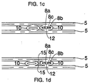
- Figure 1c is partial side elevational view of a second embodiment of the present invention in a compressed state.
- Figure 1d is a partial side elevational view of an alternative to the first embodiment shown in figure 1b.
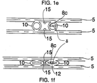
- Figure 1e is a partial side elevational view of a third embodiment of the invention.
- Figure 1f is a partial side elevational view of the third embodiment of the invention in a compressed state.
- Figure 2a is a partial side elevational view of a fourth embodiment of the present invention.
- Figure 2b is a partial side elevational view of the embodiment of figure 2a shown in a compressed state.
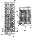
- Figure 3 is a partial side elevational view of a dye spring incorporating the first embodiment of the present invention.
- Figure 4 is a partial side elevational view of the dye spring of figure 3 in the compressed state.
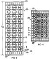
- Figure 5 is a partial side elevational view of a dye spring incorporating the fourth embodiment of the present invention.
- Figure 6 is a partial side elevational view of the dye spring of figure 5 in the compressed state.
- Figure 7 is a partial side elevational view of a section of the dye spring under a tensile load.
- Figure 8 is a top perspective view of the dye spring
- FIGS. 1a, 2a, 3 and 5 depict a dye spring constructed in accordance with the principles of the present invention.
- the dye spring structure and dye spring itself is shown in figures 1a, 2a, 3 and 5.
- End rings 25 define the outer edge of the dye spring, with the rings 5 being spaced intermediate the end rings 25.
- Rings 5 and end rings 25 define a cylindrical surface area along the longitudinal axis of the dye spring, with the length of that axis itself L30 defined by the spacing of the rings 5 and end rings 25, and the number of rings 5.
- Outer members 10 are integrally formed with rings 5 and 25 and in combination with rings 5 and 25 define a cylindrical open surface area along the dye spring.
- Outer members 10 may be circular in shape, as is shown in figure 1a and 3, or it may have the shape of a square, rectangle, or other parallelogram as shown in figures 2a and 5.
- Inner members 8a, 8b are integrally formed upon the outer members 10.
- Outer member 10, as well as inner members 8a, 8b lie in the circumferential plane P formed within the circumferential surface area of the dye spring. See figure 9.
- Inner members 8a, 8b have a length dimension L (see figure 2a) so that they nearly abut each other when the dye spring is in the uncollapsed and unelongated state.
- Inner members 8a and 8b are connected by bridge 8c which is integral with inner members 8a and 8b.
- Bridge 8c is relatively thinner than members 8a and 8b and will elongate upon compression of the dye spring. See figure 1b.
- bridge 8c can be designed to fracture upon compression. See figures 1c, 1d. Under either alternative, bridge 8c provides resistance which inhibits the occurrence of total dye spring collapse.
- the rings can be additionally provided with axial spacing stops 15 integral with the rings 5, which extend into the space between the rings, grouped together in pairs parallel to the longitudinal axis of the dye spring.
- Axial spacing stops 15 are dimensioned so that upon compression of the dye spring the pairs of stops will not abut each other so that yarn pinching, an adverse condition, will be avoided.
- the dye springs of the present invention are designed so as to collapse axially when a predetermined force is applied to the dye spring.
- the predetermined force will generally be an amount required to collapse the dye spring after the winding the yarn upon the dye spring.
- the network of outer members inner members function to insure that a portion of the cylindrical surface area of the dye spring remains open during and after collapse of the dye spring so that dye can flow through the spaces in the cylindrical area upon the dye spring and contact the yarn wound upon the spring.
- the dye spring is shown in a collapsed position in figures 1b, 1c, 1d, 1e, 2b, 4 and 6.
- bridge 8c resists the compressive forces that may develop during winding.
- the combination of adjacent outer members or outer member and adjacent stops prevent the total collapse of the dye spring which would effectively prohibit or reduce the flow of dye radially outwardly through the dye spring.
- the inner and outer members also prevent or at least substantially diminish the degree of elongation experienced by the dye spring during the winding operation. Elongation is the result of torsional forces exerted on the dye spring during the winding operation and could result in buckling of the dye spring or cause the dye spring to jump out of the winding mandrel. As illustrated in figure 7 tensile forces are exerted upon the dye spring 30, urging the dye spring to elongate as designated by arrows T. As a result of this urging the opposite sides of the outer members 11, 12 will tend to move closer together as shown by the arrows A and A".
- FIG le An alternative embodiment is shown in figure le, wherein only one inner member 8 is provided with a bridge 8c.
- This embodiment would also function to prevent compression and elongation in the manner set forth for the embodiment having inner members 8a and 8b.
- Figure lf shows this embodiment in a compressed state, where bridge 8c has been fractured.
- the dye springs of the present invention are preferably integral and injection molded from polypropylene and similar thermoplastic resins and modifications thereof.
- the material used should be able to withstand the elevated temperatures of dye baths and should provide sufficient structural integrity to endure the various forces described above and other forces apparent to the skilled artisan.
Landscapes
- Engineering & Computer Science (AREA)
- Textile Engineering (AREA)
- Springs (AREA)
- Dental Preparations (AREA)
- Materials For Medical Uses (AREA)
- Mechanical Pencils And Projecting And Retracting Systems Therefor, And Multi-System Writing Instruments (AREA)
- Luminescent Compositions (AREA)
- Storage Of Web-Like Or Filamentary Materials (AREA)
Abstract
Description
- This invention is directed towards improvements in collapsible dye tubes, commonly referred to as dye springs. The dye springs of the present invention are resiliently compressible and are further able to withstand elongation. The dye spring has a surface area of cylindrical shape with elements disposed between rings at the end of the tube. The elements insure that the dye spring surface area remains open when the dye spring is in a compressed state so that dye will be able to flow radially outwardly through the dye spring and thereby dye the yarn wound around the dye spring.The elements further insure that the degree of elongation and/or compression experienced by the dye spring during winding operations is substantially diminished or even eliminated.
- Generally, dye springs are made of a molded thermoplastic material that is collapsible and are disposable after a single use. The dye spring is wound with yarn and the yarn dyed. The yarn thereafter is wound off the dye spring and the dye spring is discarded. The dye spring of prior art U.S. Patent No. 4,181,274 comprises a pair of annular flanges and an intermediate structure between the flanges comprising at least one member extending generally axially to the length of the dye spring and a plurality of rigid members, such as rings or helices, that extend generally transversely to the length of the dye spring. The members are integrally formed by molding to initially define a rigid structure having an open network with at least some of these rigidly extending members being deformable by an axial force to cause axial compression of the dye spring. These members are referred to as ribs which form an open network to permit passage of dye therethrough.
- Prior art U.S. Patent No. 3,465,984 discloses a carrier resiliently compressible in the axial direction which comprises end rings and at least one intermediate ring with a plurality of ribs disposed between the end rings. These ribs are elastically bendable and equally distributed along the periphery of the carrier and inclined for at least a part of their length to the longitudinal axis of the carrier. The outer edges of the ribs are oriented toward the surface of the carrier, the ribs being rigidly secured to the rings.
- These prior art attempts to insure that the cylindrical surface of the dye spring remains sufficiently open after compression have not been entirely successful. Frequently the members deform so that the surface of the dye springs become closed, effectively limiting, if not prohibiting, dye flow. The phenomenon of spring elongation and/or compression, which is caused by the torsional forces applied to the spring during winding operations is addressed in
EP 0 348 721. Elongation is highly adverse because it causes the dye springs to buckle and possibly jump out of the winding machines or prevent machines from automatically doffing. Compression usually causes the dye spring to jump out of the machine. -
EP 0 348 721 discloses a collapsible dye spring according to the preamble of claim 1. The end rings and intermediate rings are connected through spacing members which extend in a zig-zag shape from one end ring to the other. When the dye spring is axially compressed these spacing members will yield. - This known dye spring further more comprises stiffening members which extend parallel to the longitudinal axis of the dye spring and interconnect the end rings and the intermediate rings. The stiffening members are provided to increase the dimensional stability of the spool, in particular to prevent elongation of the dye spring during winding of the yarn. The stiffening members are disposed in the area between adjacent spacing members.
- For connecting two adjacent rings the stiffening member comprises two parts which are joined by a breakable bridge. The bridge is designed to break when the dye spring is axially compressed.
- During the winding of the yarn the bridge is subjected to tensile forces. The bridge is sufficiently strong to withstand those tensile forces, such a strong bridge is however disadvantageous when the dye spring is compressed axially.
- During axial compression of the dye spring the parts of the stiffening members which were joined by a bridge move essentially transverse to the yarn wound on the dye spring. This could lead to pinching of the yarn and is avoided by a special design and recessed arrangement of the stiffening members.
-
EP 0 471 353 discloses a dye tube having an end ring at both ends, the end rings being connected by rigid axial stays. The axial stays are interconnected by transverse ribs, which extend around the dye tube as intermediate rings. Each transverse rib is at one end thereof integral with an axial stay. The other end of the transverse rib is connected to the adjacent axial stay through a deformable member. This known dye tube is intended for yarn which will shrink after it is wound on the dye tube. - Shrinking of the yarn leads to a deformation of the deformable members of the dye tube and a reduction of the diameter of the dye tube.
- It is an object of the invention to provide an improved dye spring which is open on at least part of its surface when it is compressed, and resists and withstands elongation and/or compression during the winding operation.
- Other objects shall become apparent from the following disclosure.
- The present invention is directed towards a dye spring that is resiliently compressible in the axial direction and is able to prohibit or prevent elongation and/or compression in the axial direction. The dye spring generally has a surface area of cylindrical shape with elements disposed between rings at the end of the dye spring. The elements are generally comprised of at least one ring member, and a plurality of spaced, rigid stays that are integrally formed with the rings and define therewith an initially rigid network for winding yarn which is to be dyed. The elements are generally comprised of a structure of outer members and inner members appearing upon and integral with the outer members. The outer members are integral with the rings and define an area in the spaces between the rings. The inner members are integral with the outer members and lie in the circumferential plane formed by the rings of dye spring. The network of outer members and inner members cooperate to insure that a portion of the circumferential surface of the dye spring remains open upon compression of the dye spring so that dye can flow radially outwardly through the open spacing. The network of outer and inner members further cooperate to substantially diminish or prevent the dye spring from elongating and/or compressing during winding. According to a preferred embodiment axial spacing stops are provided that are integral with the rings and formed in pairs. Each member of the pair sits adjacent to the other member of the pair with the pairs being aligned so that each pair is substantially parallel along an axis formed along the length of the dye spring.
- Figure 1a is a partial side elevational view of a first embodiment of the present invention.
- Figure 1b is a partial side elevational view of the embodiment of figure 1a shown in a compressed state.
- Figure 1c is partial side elevational view of a second embodiment of the present invention in a compressed state.
- . Figure 1d is a partial side elevational view of an alternative to the first embodiment shown in figure 1b.
- Figure 1e is a partial side elevational view of a third embodiment of the invention.
- Figure 1f is a partial side elevational view of the third embodiment of the invention in a compressed state.
- Figure 2a is a partial side elevational view of a fourth embodiment of the present invention.
- Figure 2b is a partial side elevational view of the embodiment of figure 2a shown in a compressed state.
- Figure 3 is a partial side elevational view of a dye spring incorporating the first embodiment of the present invention.
- Figure 4 is a partial side elevational view of the dye spring of figure 3 in the compressed state.
- Figure 5 is a partial side elevational view of a dye spring incorporating the fourth embodiment of the present invention.
- Figure 6 is a partial side elevational view of the dye spring of figure 5 in the compressed state.
- Figure 7 is a partial side elevational view of a section of the dye spring under a tensile load.
- Figure 8 is a top perspective view of the dye spring
- The figures depict a dye spring constructed in accordance with the principles of the present invention. The dye spring structure and dye spring itself is shown in figures 1a, 2a, 3 and 5. End rings 25 define the outer edge of the dye spring, with the
rings 5 being spaced intermediate the end rings 25.Rings 5 and end rings 25 define a cylindrical surface area along the longitudinal axis of the dye spring, with the length of that axis itself L30 defined by the spacing of therings 5 and end rings 25, and the number ofrings 5. -
Outer members 10 are integrally formed withrings rings Outer members 10 may be circular in shape, as is shown in figure 1a and 3, or it may have the shape of a square, rectangle, or other parallelogram as shown in figures 2a and 5.Inner members outer members 10.Outer member 10, as well asinner members Inner members Inner members bridge 8c which is integral withinner members Bridge 8c is relatively thinner thanmembers bridge 8c provides resistance which inhibits the occurrence of total dye spring collapse. - The rings can be additionally provided with axial spacing stops 15 integral with the
rings 5, which extend into the space between the rings, grouped together in pairs parallel to the longitudinal axis of the dye spring. Axial spacing stops 15 are dimensioned so that upon compression of the dye spring the pairs of stops will not abut each other so that yarn pinching, an adverse condition, will be avoided. The dye springs of the present invention are designed so as to collapse axially when a predetermined force is applied to the dye spring. The predetermined force will generally be an amount required to collapse the dye spring after the winding the yarn upon the dye spring. - When the dye spring is collapsed, the network of outer members inner members function to insure that a portion of the cylindrical surface area of the dye spring remains open during and after collapse of the dye spring so that dye can flow through the spaces in the cylindrical area upon the dye spring and contact the yarn wound upon the spring. The dye spring is shown in a collapsed position in figures 1b, 1c, 1d, 1e, 2b, 4 and 6.
- During collapse, the dye spring becomes compressed, forcing the rings closer together, compressing the
outer members 10 so that they become elongated in shape. As shown in figures 1b, 4, and 8, the circular outer members become elongated and take on an oval shape. A similar effect can be observed for the parallelogram shaped outer members in figures 2b and 6. Theinner members outer members 10, move outwardly and away from each other thus stretching or fracturing thebridge 8c as shown in figures 1b and 8 when a compression force C is applied to the dye spring. Referring to figures 1b and 2b, the movement of theinner members outer members 10 stretchesbridge 8c.Bridge 8c may also fracture due to the elongating effect. In any event, the stretching ofbridge 8c resists the compressive forces that may develop during winding. The combination of adjacent outer members or outer member and adjacent stops prevent the total collapse of the dye spring which would effectively prohibit or reduce the flow of dye radially outwardly through the dye spring. - An additional manner of preventing total collapse is to space adjacent outer members so that upon collapse, the elongated outer members will abut each other and thereby provide an additional source of resistance to total collapse. See figure 1c. This embodiment can be provided for by omitting axial spacing stops in 15.
- The inner and outer members also prevent or at least substantially diminish the degree of elongation experienced by the dye spring during the winding operation. Elongation is the result of torsional forces exerted on the dye spring during the winding operation and could result in buckling of the dye spring or cause the dye spring to jump out of the winding mandrel. As illustrated in figure 7 tensile forces are exerted upon the
dye spring 30, urging the dye spring to elongate as designated by arrows T. As a result of this urging the opposite sides of theouter members 11, 12 will tend to move closer together as shown by the arrows A and A". Because theinner members bridge 8c and are dimensioned to abut each other upon elongation of the spring, the abutting action of theinner members bridge 8c will further prohibit the outer members from moving closer together, stabilizing the dye spring against further elongation. It should be apparent to a person skilled in the art that while it is not necessary for the inner members to abut each other, they should be of a sufficient length so that they will be caused to abut during the application of a torsional force and prohibit an undesired degree of elongation. - An alternative embodiment is shown in figure le, wherein only one
inner member 8 is provided with abridge 8c. This embodiment would also function to prevent compression and elongation in the manner set forth for the embodiment havinginner members bridge 8c has been fractured. - The dye springs of the present invention are preferably integral and injection molded from polypropylene and similar thermoplastic resins and modifications thereof. The material used should be able to withstand the elevated temperatures of dye baths and should provide sufficient structural integrity to endure the various forces described above and other forces apparent to the skilled artisan.
Claims (5)
- A dye spring (30) comprised of:a pair of end rings (25);at least one intermediate ring (5), said intermediate ring being arranged between said end rings and concentrically relative to said end rings;a plurality of elements (8,8a,8b;10;11;12) disposed between the end rings and defining with said end rings and said at least one intermediate ring an open cylindrical surface area about the longitudinal axis of the dye spring, said elements being grouped in a circumferential plane (P) within the cylindrical surface area;said elements being comprised of outer members (10;11;12) being integral with said end rings and said at least one intermediate ring, each outer member defining an area within said outer member between the end rings and the at least one intermediate ring;said elements further being comprised of inner members (8,8a,8b),an inner member (8) or a pair of inner members (8a,8b) being disposed within the area defined by an outer member (10;11;12),said inner member or said pair of inner members (8,8a,8b) being integral with the outer member at opposite sides thereof, and a bridge (8c) being provided which joins said inner member to said outer member or joins said inner members of said pair of inner members to each other, said bridge stretching or fracturing when the dye spring is subjected to axial compression, characterized in thatsaid inner member (8) or said pair of inner members (8a,8b) are (is) integral with the outer member at opposite sides thereof and are located substantially in a plane transverse to the longitudinal axis of the dye spring, so that they move away from each other during axial compression of the dye spring and tend to move closer together upon axial elongation of the dye spring, and in that the members which are joined by the bridge (8c) are dimensioned to abut each other upon axial elongation of the dye spring, stabilizing the dye spring against further axial elongation.
- A dye spring according to claim 1, wherein the dye spring, for preventing total collapse of the dye spring under axial compression, is further comprised of axial spacing stops (15) integral with said end rings (25) and said at least one intermediate ring (5).
- A dye spring according to claim 2, wherein the axial spacing stops (15) are grouped in pairs, a pair of axial spacing stops being disposed in the space between adjacent outer members, said pair of axial spacing stops (15) being aligned substantially parallel to the longitudinal axis of said dye spring, the axial spacing stops being dimensioned so that upon axial compression of the dye spring the adjacent outer members will abut the axial spacing stops and the axial spacing stops will not abut each other.
- A dye spring according to claim 1, wherein a pair of inner members (8a,8b) is disposed within the area defined by an outer member, each inner member of said pair having a length dimension that is substantially transverse to the longitudinal axis of the dye spring, the length dimension of each inner member being sufficient to ensure that a compressional force will be applied to the inner members of said pair when the dye spring is subjected to torsional forces.
- A dye spring according to claim 4, wherein the inner members of said pair of inner members nearly abut when the dye spring is in an uncompressed or unelongated state.
Applications Claiming Priority (2)
| Application Number | Priority Date | Filing Date | Title |
|---|---|---|---|
| US07/962,132 US5427322A (en) | 1992-10-16 | 1992-10-16 | Dye spring |
| US962132 | 1992-10-16 |
Publications (2)
| Publication Number | Publication Date |
|---|---|
| EP0593104A1 EP0593104A1 (en) | 1994-04-20 |
| EP0593104B1 true EP0593104B1 (en) | 1997-09-17 |
Family
ID=25505463
Family Applications (1)
| Application Number | Title | Priority Date | Filing Date |
|---|---|---|---|
| EP93201734A Expired - Lifetime EP0593104B1 (en) | 1992-10-16 | 1993-06-16 | Improved dye spring |
Country Status (6)
| Country | Link |
|---|---|
| US (1) | US5427322A (en) |
| EP (1) | EP0593104B1 (en) |
| AT (1) | ATE158353T1 (en) |
| DE (1) | DE69313968T2 (en) |
| ES (1) | ES2106953T3 (en) |
| GR (1) | GR3024770T3 (en) |
Families Citing this family (3)
| Publication number | Priority date | Publication date | Assignee | Title |
|---|---|---|---|---|
| US6719230B2 (en) | 2002-01-29 | 2004-04-13 | Sonoco Development, Inc. | Collapsible yarn carrier tube |
| CN110546264A (en) | 2017-05-10 | 2019-12-06 | 丝芭博株式会社 | Method for producing polypeptide solution and polypeptide fiber, and artificial polypeptide |
| CN113718442B (en) * | 2021-08-25 | 2022-06-03 | 绍兴创彩针纺科技有限公司 | Rayon fabric pretreatment process |
Citations (1)
| Publication number | Priority date | Publication date | Assignee | Title |
|---|---|---|---|---|
| EP0348721A1 (en) * | 1988-06-30 | 1990-01-03 | Tubettificio Europa S.P.A. | Axially compressible spool |
Family Cites Families (11)
| Publication number | Priority date | Publication date | Assignee | Title |
|---|---|---|---|---|
| DE1635084C3 (en) * | 1966-11-10 | 1974-01-17 | Gerhard 5600 Wuppertalcronenberg Tigges | Winding carriers for treating threads or yarns |
| US3929301A (en) * | 1975-02-18 | 1975-12-30 | Frank Fyans | Dye tube for compressive packaged dyeing |
| US4181274A (en) * | 1976-10-22 | 1980-01-01 | Burchette Robert L Jr | Dye tube |
| US4454734A (en) * | 1980-09-25 | 1984-06-19 | Plastech, Inc. | Rigid and compressible dye tubes |
| DE8411284U1 (en) * | 1984-04-11 | 1984-08-16 | Hahm, Manfred, 5100 Aachen | CHANGER |
| US4789111A (en) * | 1987-11-05 | 1988-12-06 | Crellin, Inc. | Dye tube |
| US4872621A (en) * | 1987-11-05 | 1989-10-10 | Crellin, Inc. | Spring dye tube |
| AT404720B (en) * | 1988-01-23 | 1999-02-25 | Becker Josef | METHOD AND DYEING CASE FOR COMPENSATING YARN EVENLY |
| DE3844006A1 (en) * | 1988-12-27 | 1990-07-05 | Adolff Emil Plastic Gmbh | PRESS RELEASE |
| DE9011919U1 (en) * | 1990-08-17 | 1990-12-06 | Jos. Zimmermann GmbH & Co KG, 5100 Aachen | Shrink sleeve |
| US5094404A (en) * | 1991-05-15 | 1992-03-10 | Crellin, Inc. | Dye spring elongated membrane design |
-
1992
- 1992-10-16 US US07/962,132 patent/US5427322A/en not_active Expired - Lifetime
-
1993
- 1993-06-16 EP EP93201734A patent/EP0593104B1/en not_active Expired - Lifetime
- 1993-06-16 DE DE69313968T patent/DE69313968T2/en not_active Expired - Fee Related
- 1993-06-16 AT AT93201734T patent/ATE158353T1/en not_active IP Right Cessation
- 1993-06-16 ES ES93201734T patent/ES2106953T3/en not_active Expired - Lifetime
-
1997
- 1997-09-18 GR GR970402154T patent/GR3024770T3/en unknown
Patent Citations (1)
| Publication number | Priority date | Publication date | Assignee | Title |
|---|---|---|---|---|
| EP0348721A1 (en) * | 1988-06-30 | 1990-01-03 | Tubettificio Europa S.P.A. | Axially compressible spool |
Also Published As
| Publication number | Publication date |
|---|---|
| EP0593104A1 (en) | 1994-04-20 |
| GR3024770T3 (en) | 1997-12-31 |
| US5427322A (en) | 1995-06-27 |
| DE69313968D1 (en) | 1997-10-23 |
| DE69313968T2 (en) | 1998-01-22 |
| ES2106953T3 (en) | 1997-11-16 |
| ATE158353T1 (en) | 1997-10-15 |
Similar Documents
| Publication | Publication Date | Title |
|---|---|---|
| CA1079702A (en) | Dye tube | |
| DE69907605T2 (en) | Rubber glove or the like | |
| US5427322A (en) | Dye spring | |
| US3759460A (en) | Collapsible yarn dye tube | |
| US4941621A (en) | Axially compressible spool | |
| US5445335A (en) | Coil carrier compressible in axial direction | |
| US4789111A (en) | Dye tube | |
| US4872621A (en) | Spring dye tube | |
| DE2506512C3 (en) | Textile sleeve | |
| US5820049A (en) | Rigid plastic dye tube | |
| US5131595A (en) | Axially deformable bobbin for dyeing spools | |
| US6719230B2 (en) | Collapsible yarn carrier tube | |
| EP0471353B1 (en) | Shrink bobbin | |
| EP0469394B1 (en) | Axially compressible yarn windings waps tube | |
| EP0943465A1 (en) | Vehicle wheel with in particular a one-piece-rim and a tubeless tyre ,specially adapted for runflat operation | |
| DE3824176C2 (en) | ||
| US3936009A (en) | Collapsible dye tube | |
| EP0209799A1 (en) | Device for radially movably fixing the casing of a spindle bearing of a spinning or twisting spindle on a spindle rail | |
| DE3629401A1 (en) | AXIAL DEFORMABLE TEXTILE SLEEVE | |
| US4441665A (en) | Axially telescopic coil carrier | |
| EP0795430B1 (en) | Collapsible tube for car door handles | |
| DE10206002C1 (en) | Welding wire coil reel has coil reel frame wih spaced frame rings joined via hoop elements fitted to carrier secured to coil reel core | |
| ITMI940145A1 (en) | RADIALLY COMPRESSABLE TUBE FOR WINDING YARNS | |
| US5411217A (en) | Compressible bobbin for yarn treatment | |
| JP3490004B2 (en) | Bobbin |
Legal Events
| Date | Code | Title | Description |
|---|---|---|---|
| PUAI | Public reference made under article 153(3) epc to a published international application that has entered the european phase |
Free format text: ORIGINAL CODE: 0009012 |
|
| AK | Designated contracting states |
Kind code of ref document: A1 Designated state(s): AT BE CH DE DK ES FR GB GR IE IT LI LU MC NL PT SE |
|
| 17P | Request for examination filed |
Effective date: 19940519 |
|
| 17Q | First examination report despatched |
Effective date: 19950807 |
|
| GRAG | Despatch of communication of intention to grant |
Free format text: ORIGINAL CODE: EPIDOS AGRA |
|
| GRAH | Despatch of communication of intention to grant a patent |
Free format text: ORIGINAL CODE: EPIDOS IGRA |
|
| GRAH | Despatch of communication of intention to grant a patent |
Free format text: ORIGINAL CODE: EPIDOS IGRA |
|
| GRAA | (expected) grant |
Free format text: ORIGINAL CODE: 0009210 |
|
| AK | Designated contracting states |
Kind code of ref document: B1 Designated state(s): AT BE CH DE DK ES FR GB GR IE IT LI LU MC NL PT SE |
|
| REF | Corresponds to: |
Ref document number: 158353 Country of ref document: AT Date of ref document: 19971015 Kind code of ref document: T |
|
| REG | Reference to a national code |
Ref country code: CH Ref legal event code: NV Representative=s name: PATENTANWALTSBUERO FELDMANN AG Ref country code: CH Ref legal event code: EP |
|
| REF | Corresponds to: |
Ref document number: 69313968 Country of ref document: DE Date of ref document: 19971023 |
|
| ET | Fr: translation filed | ||
| REG | Reference to a national code |
Ref country code: ES Ref legal event code: FG2A Ref document number: 2106953 Country of ref document: ES Kind code of ref document: T3 |
|
| REG | Reference to a national code |
Ref country code: GR Ref legal event code: FG4A Free format text: 3024770 |
|
| ITF | It: translation for a ep patent filed | ||
| REG | Reference to a national code |
Ref country code: IE Ref legal event code: FG4D Free format text: 76495 |
|
| REG | Reference to a national code |
Ref country code: PT Ref legal event code: SC4A Free format text: AVAILABILITY OF NATIONAL TRANSLATION Effective date: 19971118 |
|
| PLBE | No opposition filed within time limit |
Free format text: ORIGINAL CODE: 0009261 |
|
| STAA | Information on the status of an ep patent application or granted ep patent |
Free format text: STATUS: NO OPPOSITION FILED WITHIN TIME LIMIT |
|
| 26N | No opposition filed | ||
| REG | Reference to a national code |
Ref country code: GB Ref legal event code: IF02 |
|
| PGFP | Annual fee paid to national office [announced via postgrant information from national office to epo] |
Ref country code: PT Payment date: 20040616 Year of fee payment: 12 Ref country code: GB Payment date: 20040616 Year of fee payment: 12 |
|
| PGFP | Annual fee paid to national office [announced via postgrant information from national office to epo] |
Ref country code: NL Payment date: 20040623 Year of fee payment: 12 |
|
| PGFP | Annual fee paid to national office [announced via postgrant information from national office to epo] |
Ref country code: DE Payment date: 20040624 Year of fee payment: 12 |
|
| PGFP | Annual fee paid to national office [announced via postgrant information from national office to epo] |
Ref country code: LU Payment date: 20040625 Year of fee payment: 12 Ref country code: FR Payment date: 20040625 Year of fee payment: 12 |
|
| PGFP | Annual fee paid to national office [announced via postgrant information from national office to epo] |
Ref country code: IE Payment date: 20040628 Year of fee payment: 12 Ref country code: SE Payment date: 20040628 Year of fee payment: 12 Ref country code: MC Payment date: 20040628 Year of fee payment: 12 Ref country code: GR Payment date: 20040628 Year of fee payment: 12 Ref country code: AT Payment date: 20040628 Year of fee payment: 12 |
|
| PGFP | Annual fee paid to national office [announced via postgrant information from national office to epo] |
Ref country code: DK Payment date: 20040629 Year of fee payment: 12 Ref country code: CH Payment date: 20040629 Year of fee payment: 12 |
|
| PGFP | Annual fee paid to national office [announced via postgrant information from national office to epo] |
Ref country code: ES Payment date: 20040719 Year of fee payment: 12 |
|
| PGFP | Annual fee paid to national office [announced via postgrant information from national office to epo] |
Ref country code: BE Payment date: 20040813 Year of fee payment: 12 |
|
| PG25 | Lapsed in a contracting state [announced via postgrant information from national office to epo] |
Ref country code: LU Free format text: LAPSE BECAUSE OF NON-PAYMENT OF DUE FEES Effective date: 20050616 Ref country code: IT Free format text: LAPSE BECAUSE OF NON-PAYMENT OF DUE FEES Effective date: 20050616 Ref country code: IE Free format text: LAPSE BECAUSE OF NON-PAYMENT OF DUE FEES Effective date: 20050616 Ref country code: AT Free format text: LAPSE BECAUSE OF NON-PAYMENT OF DUE FEES Effective date: 20050616 |
|
| PG25 | Lapsed in a contracting state [announced via postgrant information from national office to epo] |
Ref country code: SE Free format text: LAPSE BECAUSE OF NON-PAYMENT OF DUE FEES Effective date: 20050617 Ref country code: ES Free format text: LAPSE BECAUSE OF NON-PAYMENT OF DUE FEES Effective date: 20050617 |
|
| PG25 | Lapsed in a contracting state [announced via postgrant information from national office to epo] |
Ref country code: MC Free format text: LAPSE BECAUSE OF NON-PAYMENT OF DUE FEES Effective date: 20050630 Ref country code: LI Free format text: LAPSE BECAUSE OF NON-PAYMENT OF DUE FEES Effective date: 20050630 Ref country code: DK Free format text: LAPSE BECAUSE OF NON-PAYMENT OF DUE FEES Effective date: 20050630 Ref country code: CH Free format text: LAPSE BECAUSE OF NON-PAYMENT OF DUE FEES Effective date: 20050630 Ref country code: BE Free format text: LAPSE BECAUSE OF NON-PAYMENT OF DUE FEES Effective date: 20050630 |
|
| PG25 | Lapsed in a contracting state [announced via postgrant information from national office to epo] |
Ref country code: PT Free format text: LAPSE BECAUSE OF NON-PAYMENT OF DUE FEES Effective date: 20051216 |
|
| PG25 | Lapsed in a contracting state [announced via postgrant information from national office to epo] |
Ref country code: NL Free format text: LAPSE BECAUSE OF NON-PAYMENT OF DUE FEES Effective date: 20060101 |
|
| PG25 | Lapsed in a contracting state [announced via postgrant information from national office to epo] |
Ref country code: GR Free format text: LAPSE BECAUSE OF NON-PAYMENT OF DUE FEES Effective date: 20060103 Ref country code: DE Free format text: LAPSE BECAUSE OF NON-PAYMENT OF DUE FEES Effective date: 20060103 |
|
| REG | Reference to a national code |
Ref country code: CH Ref legal event code: PL |
|
| EUG | Se: european patent has lapsed | ||
| PG25 | Lapsed in a contracting state [announced via postgrant information from national office to epo] |
Ref country code: FR Free format text: LAPSE BECAUSE OF NON-PAYMENT OF DUE FEES Effective date: 20060228 |
|
| GBPC | Gb: european patent ceased through non-payment of renewal fee |
Effective date: 20050616 |
|
| NLV4 | Nl: lapsed or anulled due to non-payment of the annual fee |
Effective date: 20060101 |
|
| REG | Reference to a national code |
Ref country code: DK Ref legal event code: EBP |
|
| REG | Reference to a national code |
Ref country code: IE Ref legal event code: MM4A |
|
| REG | Reference to a national code |
Ref country code: FR Ref legal event code: ST Effective date: 20060228 |
|
| REG | Reference to a national code |
Ref country code: ES Ref legal event code: FD2A Effective date: 20050617 |
|
| BERE | Be: lapsed |
Owner name: *CRELLIN INC. Effective date: 20050630 |