EP0592817A1 - Gasturbogruppe mit einer Druckwellenmaschine als Brennkammer - Google Patents
Gasturbogruppe mit einer Druckwellenmaschine als Brennkammer Download PDFInfo
- Publication number
- EP0592817A1 EP0592817A1 EP93114657A EP93114657A EP0592817A1 EP 0592817 A1 EP0592817 A1 EP 0592817A1 EP 93114657 A EP93114657 A EP 93114657A EP 93114657 A EP93114657 A EP 93114657A EP 0592817 A1 EP0592817 A1 EP 0592817A1
- Authority
- EP
- European Patent Office
- Prior art keywords
- pressure
- turbine
- compressor
- wheel
- medium
- Prior art date
- Legal status (The legal status is an assumption and is not a legal conclusion. Google has not performed a legal analysis and makes no representation as to the accuracy of the status listed.)
- Granted
Links
Images
Classifications
-
- F—MECHANICAL ENGINEERING; LIGHTING; HEATING; WEAPONS; BLASTING
- F02—COMBUSTION ENGINES; HOT-GAS OR COMBUSTION-PRODUCT ENGINE PLANTS
- F02C—GAS-TURBINE PLANTS; AIR INTAKES FOR JET-PROPULSION PLANTS; CONTROLLING FUEL SUPPLY IN AIR-BREATHING JET-PROPULSION PLANTS
- F02C3/00—Gas-turbine plants characterised by the use of combustion products as the working fluid
- F02C3/02—Gas-turbine plants characterised by the use of combustion products as the working fluid using exhaust-gas pressure in a pressure exchanger to compress combustion-air
Definitions
- the invention relates to a gas turbine group according to the preamble of patent claim 1.
- a first outlet opening of the pressure wave machine is connected to the high pressure turbine and a second outlet opening of the pressure wave machine is connected to the low pressure turbine together with the outlet of the high pressure turbine.
- the object which is to be achieved with the present invention is to create a gas turbine group which is able to optimally process the pressure drop of two hot gas streams of different pressure emerging from the pressure wave machine and to improve the efficiency of the turbine by improving the expansion process increase.
- the use of a double spiral has the advantage that more pressure drops and more volume flow can be processed at the same time.
- the double-spiral radial turbine can replace two turbines, namely a high-pressure turbine and a medium-pressure turbine, the efficiency being additionally improved. It is particularly advantageous that the parallel expansion of two hot gas mass flows from the high-pressure propellant line and from the low-pressure propellant line results in thorough mixing at the outlet of the radial turbine with a double spiral.
- the parallel expansion of the high pressure and medium pressure partial flow in just one turbine makes it possible to change the performance of the high pressure medium pressure turbine within certain limits. This enables the performance balances or the individual components to be optimized better.
- the low pressure turbine can in this case be an independent, i.e. free-running power turbine are operated.
- a pressure wave machine 10 is connected to a high pressure turbine 12 via a high pressure propellant gas line 11 and to a low pressure turbine 14 via a low pressure propellant gas line 13.
- An outlet line 15 of the high-pressure turbine 12 opens at the branch 16 into the low-pressure propellant gas line 13.
- a pressure wave machine 19 is arranged between a high-pressure compressor 17 and a high-pressure medium-pressure turbine 18.
- This pressure wave machine 19 has isocore combustion chambers 42.
- a low-pressure compressor 20 is connected to the high-pressure compressor 17 and a low-pressure turbine 21 is connected to the high-pressure medium-pressure turbine 18.
- a combustion chamber 43 with a burner 44 is located between the high-pressure medium-pressure turbine 18 and the low-pressure turbine 21.
- a turbine wheel 22 of the high-pressure medium-pressure turbine 18 drives a compressor wheel 24 of the high-pressure compressor 17 via a first shaft 23.
- a turbine wheel 25 of the low-pressure turbine 21 drives a compressor wheel 27 of the low-pressure compressor 20 via a second shaft 26.
- a generator 28 is driven by the turbine wheel 25 of the low-pressure turbine 21 via the same second shaft 26. If the total compressor output of the high-pressure compressor 17 and the low-pressure compressor 20 with the high-pressure medium-pressure turbine 18 is to be generated, the compressor wheel 27 is connected to the first shaft 23. In this case, only the generator 28 is driven by the turbine wheel 25 of the low-pressure turbine 21 via the second shaft 26.
- the generator 28 is also to be driven by the turbine wheel 22 of the high-pressure medium-pressure turbine 18, the turbine wheel 25 and also the generator 28 are connected to the first shaft 23 and the second shaft 26 can be omitted entirely.
- Both the high-pressure compressor 17 and the high-pressure medium-pressure turbine 18 are designed as radial compressors or as a radial turbine.
- the low-pressure compressor 20 and the low-pressure turbine 21 are designed as an axial compressor or as an axial turbine.
- the high-pressure medium-pressure turbine 18 has a double spiral 30, 31.
- the pressure wave machine 19 has a cellular wheel 32 which is rotatably mounted on the first shaft 23 and contains the isocore combustion chambers 42.
- This cellular wheel 32 is located in a housing of the pressure wave machine 19. Of this housing, only two side walls 33 and 34 are indicated in FIG. 2. These side walls 33 and 34 have inlet channels 35 and outlet channels 36.
- the inlet channels 35 are - as indicated by arrows 39, 40 - connected to the high-pressure compressor 17 by lines, not shown, and the outlet channels 36 are - as indicated by arrows 37 and 38 - by a high-pressure propellant gas line 37, not shown, and a medium-pressure propellant gas line 38, not shown, connected to the double spiral 30 and 31 of the high-pressure medium-pressure turbine 18.
- the operation of the described gas turbo groups is as follows: As soon as the gas turbine group is in operation, air is drawn in by the low-pressure compressor 20 in the direction of arrow 41, compressed and fed to the high-pressure compressor 17. This compressed air is further compressed in the high-pressure compressor 17 and fed to the pressure wave machine 19. In the high-pressure compressor 17, the air flows through the compressor wheel 24 into the single spiral 29 and from this the compressed air flows - as indicated by arrows 39 and 40 - into the inlet channels 35 of the pressure wave machine 19. In the pressure wave machine 19, the compressed air is mixed with fuel and set on fire.
- the hot gas flows emerging from the pressure wave machine 19 pass through the outlet channels 36 - as indicated by arrows 37 and 38 - into the two parts 30 and 31 of the double spiral 30, 31 of the high-pressure medium-pressure turbine 18.
- the two hot gas streams from the double spiral 30, 31 are mixed with one another and reach the low-pressure turbine 21 via the combustion chamber 43.
- the hot gas stream that comes from the high-pressure medium-pressure turbine 18 is passed on using the burner 44 is heated before it reaches the low-pressure turbine 21.
- the high-pressure compressor and the low-pressure compressor are driven by this hot gas stream flowing through the high-pressure medium-pressure turbine and the hot gas flow then flowing through the low-pressure turbine drives the generator 28.
- This turbine replaces two small radial turbines, namely a high pressure and a medium pressure turbine. Due to the parallel expansion of the two hot gas streams, thorough mixing is achieved at the turbine outlet.
- the parallel expansion of a high-pressure and a medium-pressure partial flow in a single turbine gives the possibility to change the performance of the high-pressure medium-pressure turbine within certain limits. This enables the performance balances or the individual components to be optimized better.
- the low pressure turbine can in this case be an independent, i.e. be operated as a free-running power turbine.
- the pressure wave machine 19 can be designed as a countercurrent machine.
- the cellular wheel 32 is located between the two side walls 33 and 34.
- the air-side side wall 33 has an inlet opening 35, which is connected to the compressor 17 and contains fuel nozzles 46, and an outlet opening 36, which connects to the first part 30 of the double spiral 30, 31 is connected.
- the gas side wall 34 only has an outlet opening 36 ', which is connected to the second part 31 of the double spiral 30, 31.
- the pressure wave machine 19 can be designed as a DC machine.
- the cellular wheel 32 is located between the two side walls 33 and 34.
- the air-side side wall 33 has only one inlet opening 35, which is connected to the compressor 17 and contains fuel nozzles 46.
- the gas-side wall 34 has two outlet openings 36 and 36 ', of which one outlet opening 36 is connected to the first part 30 of the double spiral 30, 31, and of which the other outlet opening 36' is connected to the second part 31 of the double spiral 30, 31 connected.
- the gas turbine group described can be used to drive a generator 28.
- the gas turbine group described can be used as a jet turbine for an aircraft.
Landscapes
- Engineering & Computer Science (AREA)
- Chemical & Material Sciences (AREA)
- Combustion & Propulsion (AREA)
- Mechanical Engineering (AREA)
- General Engineering & Computer Science (AREA)
- Structures Of Non-Positive Displacement Pumps (AREA)
Abstract
Description
- Die Erfindung betrifft eine Gasturbogruppe gemäss dem Oberbegriff des Patentanspruches 1.
- Es ist üblich, eine Turbine aus einer Hochdruckturbine und einer Niederdruckturbine aufzubauen oder, falls notwendig, die Turbine in eine Hochdruckturbine, eine Mitteldruckturbine und eine Niederdruckturbine zu unterteilen. Eine erste Austrittsöffnung der Druckwellenmaschine wird an die Hochdruckturbine angeschlossen und eine zweite Austrittsöffnung der Druckwellenmaschine wird zusammen mit dem Austritt der Hochdruckturbine an die Niederdruckturbine angeschlossen.
- Sofern jedoch zwischen Hochdruckturbine und Niederdruckturbine eine Mitteldruckturbine notwendig ist, ergeben sich Probleme.
- Die Aufgabe, welche mit der vorliegenden Erfindung gelöst werden soll, besteht in der Schaffung einer Gasturbogruppe, welche in der Lage ist, das Druckgefälle von zwei aus der Durckwellenmaschine austretenden Heissgasströmen von unterschiedlichem Druck optimal zu verarbeiten und durch Verbesserung des Entspannungsvorganges den Wirkungsgrad der Turbine zu steigern.
- Diese Aufgabe wird erfindungsgemäss dadurch gelöst, dass die Gasturbogruppe die Merkmale im Kennzeichen des Patentanspruches 1 aufweist.
- Die Verwendung einer Doppelspirale hat den Vorteil, dass gleichzeitig mehr Druckgefälle und mehr Volumenstrom verarbeitet werden kann. Die Radialturbine mit Doppelspirale kann zwei Turbinen, nämlich eine Hochdruckturbine und eine Mitteldruckturbine, ersetzen, wobei der Wirkungsgrad zusätzlich verbessert wird. Von besonderem Vorteil ist, dass durch die parallele Entspannung zweier Heissgasmassenströme aus der Hochdruck-Treibgasleitung und aus der Niederdruck-Treibgasleitung eine gute Durchmischung am Ausgang der Radialturbine mit Doppelspirale erreicht wird.
- Die Parallelentspannung des Hochdruck- und des Mitteldruck-Teilstromes in nur einer Turbine ermöglicht es, die Leistung der Hochdruck-Mitteldruck-Turbine in gewissen Grenzen zu verändern. Dadurch können die Leistungsgleichgewichte, bzw. die einzelnen Komponenten besser optimiert werden. Je nach Prozessführung ist es möglich, die gesamte Verdichterleistung des Niederdruck-Hochdruck-Verdichters mit der Hochdruck-Mitteldruck-Turbine zu erzeugen. Die Niederdruck-Turbine kann in diesem Fall als unabhängige, d.h. freilaufende Arbeitsturbine betrieben werden.
- Ein Ausführungsbeispiel der erfindungsgemässen Gasturbogruppe ist im folgenden anhand der beigefügten Zeichnung ausführlich beschrieben. Es zeigt
- Fig.1
- den Stand der Technik in schematischer Darstellung,
- Fig.2
- eine schematische Darstellung der ganzen Gasturbogruppe,
- Fig.3
- eine schematische Darstellung einer Gegenstrom-Druckwellenmaschine und
- Fig.4
- eine schematische Darstellung einer GleichstromDruckwellenmaschine.
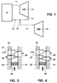
- Gemäss Fig.1 ist eine Druckwellenmaschine 10 über eine Hochdruck-Treibgasleitung 11 an eine Hockdruck-Turbine 12 und über eine Niederdruck-Treibgasleitung 13 an eine Niederdruck-Turbine 14 angeschlossen. Eine Austrittsleitung 15 der Hochdruck-Turbine 12 mündet an der Verzweigung 16 in die Niederdruck-Treibgasleitung 13.
- Diese an sich bekannte Gasturbogruppe soll nun, wie in Fig. 2 dargestellt ist, verbessert werden.
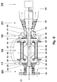
- Gemäss Fig. 2 ist zwischen einem Hochdruck-Verdichter 17 und einer Hochdruck-Mitteldruck-Turbine 18 eine Druckwellenmaschine 19 angeordnet. Diese Druckwellenmaschine 19 besitzt isocore Brennkammern 42. An dem Hochdruck-Verdichter 17 ist ein Niederdruck-Verdichter 20 angeschlossen und an die Hochdruck-Mitteldruck-Turbine 18 ist eine Niederdruck-Turbine 21 angeschlossen. Zwischen der Hochdruck-Mitteldruck-Turbine 18 und der Niederdruck-Turbine 21 befindet sich eine Brennkammer 43 mit einem Brenner 44. Ein Turbinenrad 22 der Hochdruck-Mitteldruck-Turbine 18 treibt über eine erste Welle 23 ein Verdichterrad 24 des Hochdruck-Verdichters 17 an.
- Ein Turbinenrad 25 der Niederdruck-Turbine 21 treibt über eine zweite Welle 26 ein Verdichterrad 27 des Niederdruck-Verdichters 20 an. Ausserdem wird vom Turbinenrad 25 der Niederdruck-Turbine 21 über dieselbe zweite Welle 26 ein Generator 28 angetrieben. Falls die gesamte Verdichterleistung des Hochdruck-Verdichters 17 und des Niederdruck-Verdichters 20 mit der Hochdruck-Mitteldruck-Turbine 18 erzeugt werden soll, so wird das Verdichterrad 27 an die erste Welle 23 angeschlossen. In diesem Falle wird vom Turbinenrad 25 der Niederdruck-Turbine 21 über die zweite Welle 26 ausschliesslich der Generator 28 angetrieben.
- Falls der Generator 28 auch vom Turbinenrad 22 der Hochdruck-Mitteldruck-Turbine 18 angetrieben werden soll, so wird das Turbinenrad 25 und auch der Generator 28 an die erste Welle 23 angeschlossen und die zweite Welle 26 kann gänzlich weggelassen werden.
- Sowohl der Hochdruck-Verdichter 17, als auch die Hochdruck-Mitteldruck-Turbine 18 sind als Radial-Verdichter, bzw. als Radial-Turbine ausgebildet. Hingegen sind der Niederdruck-Verdichter 20 und die Niederdruck-Turbine 21 als Achsial-Verdichter, bzw. als Achsial-Turbine, ausgebildet. Im Gegensatz zum Hochdruck-Verdichter 17, der nur eine Einfach-Spirale 29 besitzt, weist die Hochdruck-Mitteldruck-Turbine 18 eine Doppelspirale 30, 31 auf.
- Gemäss Fig. 2 weist die Druckwellenmaschine 19 ein Zellenrad 32 auf, das drehbar auf der ersten Welle 23 gelagert ist und die isocoren Brennkammern 42 enthält. Dieses Zellenrad 32 befindet sich in einem Gehäuse der Druckwellenmaschine 19. Von diesem Gehäuse sind in Fig. 2 nur zwei Seitenwände 33 und 34 angedeutet. Diese Seitenwände 33 und 34 weisen Eintrittskanäle 35 und Austrittskanäle 36 auf.
- Die Eintrittskanäle 35 sind - wie durch Pfeile 39, 40 angedeutet - durch nicht dargestellte Leitungen mit dem Hochdruck-Verdichter 17 verbunden und die Austrittskanäle 36 sind - wie durch Pfeile 37 und 38 angedeutet - durch eine nicht dargestellte Hochdruck-Treibgasleitung 37 und eine nicht dargestelle Mitteldruck-Treibgasleitung 38 mit der Doppelspirale 30 und 31 der Hochdruck-Mitteldruck-Turbine 18 verbunden.
- Die Wirkungsweise der beschriebenen Gasturbogruppen ist wie folgt:
Sobald die Gasturbogruppe einmal in Betrieb ist, wird durch den Niederdruck-Verdichter 20 Luft in Richtung des Pfeils 41 angesaugt, verdichtet und dem Hochdruck-Verdichter 17 zugeführt. Diese verdichtete Luft wird im Hochdruck-Verdichter 17 weiter verdichtet und der Druckwellenmaschine 19 zugeführt. Im Hochdruckverdichter 17 strömt durch das Verdichterrad 24 die Luft in die Einfachspirale 29 und aus dieser strömt die verdichtete Luft - wie durch Pfeile 39 und 40 angedeutet - in die Eintrittskanäle 35 der Druckwellenmaschine 19. In der Druckwellenmaschine 19 wird die komprimierte Luft mit Brennstoff vermischt und angezündet. Die aus der Druckwellenmaschine 19 austretenden Heissgasströme gelangen durch die Austrittskanäle 36 - wie durch Pfeile 37 und 38 angedeutet - in die beiden Teile 30 und 31 der Doppelspirale 30, 31 der Hochdruck-Mitteldruck-Turbine 18. Im Turbinenrad 22 der Hochdruck-Mitteldruck-Turbine 18 werden die beiden Heissgasströme aus der Doppelspirale 30, 31 miteinander vermischt und gelangen über die Brennkammer 43 in die Niederdruck-Turbine 21. In dieser Brennkammer wird mit Hilfe des Brenners 44 der Heissgasstrom, der aus der Hochdruck-Mitteldruck-Turbine 18 kommt, weiter erwärmt, bevor er in die Niederdruck-Turbine 21 gelangt. Durch diesen durch die Hochdruck-Mitteldruck-Turbine strömenden Heissgasstrom werden der Hochdruck-Verdichter und der Niederdruck-Verdichter angetrieben und durch den anschliessend durch die Niederdruck-Turbine strömenden Heissgasstrom wird der Generator 28 angetrieben. - Durch die Anwendung einer Doppelspirale 30, 31 in der Hochdruck-Mitteldruck-Turbine 18 kann gleichzeitig mehr Druckgefälle und mehr Volumenstrom verarbeitet werden.
- Diese Turbine tritt anstelle von zwei kleinen Radialturbinen, nämlich einer Hochdruck- und einer Mitteldruck-Turbine. Durch die parallele Entspannung der beiden Heissgasströme wird eine gute Durchmischung am Turbinenausgang erreicht.
- Durch die Parallelentspannung eines Hochdruck- und eines Mitteldruck-Teilstromes in einer einzigen Turbine ergibt sich die Möglichkeit, die Leistung der Hochdruck-Mitteldruck-Turbine in gewissen Grenzen zu ändern. Dadurch können die Leistungsgleichgewichte, bzw. die einzelnen Komponenten besser optimiert werden. Je nach Prozessführung ist es möglich, die gesamte Verdichterleistung des Niederdruck-Hochdruck-Verdichters mit der Hochdruck-Mitteldruck-Turbine zu erzeugen. Die Niederdruck-Turbine kann in diesem Fall als unabhängige, d.h. als freilaufende Arbeitsturbine betrieben werden.
- Gemäss Fig. 3 kann die Druckwellenmaschine 19 als Gegenstrommaschine ausgebildet sein. Das Zellenrad 32 befindet sich zwischen den beiden Seitenwänden 33 und 34. Die luftseitige Seitenwand 33 weist eine Eintrittsöffnung 35 auf, welche an den Verdichter 17 angeschlossen ist und Brennstoffdüsen 46 enthält, sowie eine Austrittsöffnung 36, welche an den ersten Teil 30 der Doppelspirale 30, 31 angeschlossen ist. Die gasseitige Seitenwand 34 weist nur eine Austrittsöffnung 36' auf, welche an den zweiten Teil 31 der Doppelspirale 30, 31 angeschlossen ist.
- Gemäss Fig. 4 kann die Druckwellenmaschine 19 als Gleichstrommaschine ausgebildet sein. Das Zellenrad 32 befindet sich zwischen den beiden Seitenwänden 33 und 34. Die luftseitige Seitenwand 33 weist nur eine Eintrittsöffnung 35 auf, welche an den Verdichter 17 angeschlossen ist und Brennstoffdüsen 46 enthält. Die gasseitige Seitenwand 34 weist zwei Austrittsöffnungen 36 und 36' auf, von denen die eine Austrittsöffnung 36 an den ersten Teil 30 der Doppelspirale 30, 31 angeschlossen ist, und von denen die andere Austrittsöffnung 36' an den zweiten Teil 31 der Doppelspirale 30, 31 angeschlossen ist.
- Die beschriebene Gasturbogruppe kann wie in Fig. 2 dargestellt, zum Antrieb eines Generators 28 verwendet werden.
- Mit Hilfe eines sogenannten Frontfans 45 kann die beschriebene Gasturbogruppe als Jet-Turbine für ein Flugzeug verwendet werden.
-
- 10
- Druckwellenmaschine (bekannt)
- 11
- Hochdruck-Treibgasleitung
- 12
- Hochdruck-Turbine
- 13
- Niederdruck-Treibgasleitung
- 14
- Niederdruck-Turbine
- 15
- Austrittsleitung
- 16
- Verzweigung
- 17
- Hochdruck-Verdichter
- 18
- Hochdruck-Mitteldruck-Turbine
- 19
- Druckwellenmaschine (neu)
- 20
- Niederdruck-Verdichter
- 21
- Niederdruck-Turbine
- 22
- Turbinenrad der Hochdruck-Mitteldruck-Turbine 18
- 23
- erste Welle
- 24
- Verdichterrad des Hochdruck-Verdichters
- 25
- Turbinenrad der Niederdruck-Turbine 21
- 26
- zweite Welle
- 27
- Verdichterrad des Niederdruck-Verdichters
- 28
- Generator
- 29
- Einfach-Spirale
- 30
- Doppel-Spirale
- 31
- Doppel-Spirale
- 32
- Zellenrad
- 33
- Seitenwand
- 34
- Seitenwand
- 35
- Eintritts-Kanäle
- 36
- Austritts-Kanäle
- 37
- Hochdruck-Treibgasleitung zur Turbine
- 38
- Mitteldruck-Treibgasleitung zur Turbine
- 39
- Leitung vom Verdichter
- 40
- Leitung vom Verdichter
- 41
- Pfeil
- 42
- Brennkammer
- 43
- Brennkammer
- 44
- Brenner
- 45
- Frontfan
- 46
- Brennstoffdüsen
Claims (8)
- Gasturbogruppe, enthaltend- eine Turbine (18) mit mindestens einer Hochdruckstufe (30) und einer Mitteldruckstufe (31);- eine Brennkammer, insbesondere eine Druckwellenmaschine (19), mit einem Zellenrad (32), welches sich zwischen je einem mit Eintritts- und Austritts-Oeffnungen (35, 36, 36') versehenen luftseitigen und gasseitigen Seitenteil (33, 34) dreht;dadurch gekennzeichnet, dass- die Hochdruck-Mitteldruck-Turbine (18) eine Doppelspirale (30, 31) aufweist, von welcher die eine Spirale (30) an eine erste Austrittsöffnung (36) der Druckwellenmaschine (19) und die andere Spirale (31) an eine zweite Austrittsöffnung (36') der Druckwellenmaschine (19) angeschlossen ist;- die Hochdruck-Mitteldruck-Turbine (18) als Radialturbine ausgebildet ist, mit einem einzigen Radialturbinenrad (22) in welchem sich die Heissgasströme der beiden Teile der Doppelspirale (30, 31) mischen.
- Druckwellenmaschine mit Turbine nach Anspruch 1, dadurch gekennzeichnet, dass die Druckwellenmaschine (19) als Gegenstrommaschine ausgebildet ist, mit einer luftseitigen Seitenwand (33), welche eine Eintrittsöffnung (35) aufweist, die an einen Verdichter (17) angeschlossen ist, sowie eine Austrittsöffnung (36) die an den ersten Teil (30) der Doppelspirale (30, 31) angeschlossen ist und mit einer gasseitigen Seitenwand (34), welche eine Austrittsöffnung (36') aufweist, die an den zweiten Teil (31) der Doppelspirale (30, 31) der Hochdruck-Mitteldruck-Turbine (18) angeschlossen ist.
- Druckwellenmaschine mit Turbine nach Anspruch 1, dadurch gekennzeichnet, dass die Druckwellenmaschine (19) als Gleichstrommaschine ausgebildet ist, mit einer luftseitigen Seitenwand (33), welche eine Eintrittsöffnung (35) aufweist, die an einen Verdichter (17) angeschlossen ist, und mit einer gasseitigen Seitenwand (34), welche zwei Austrittsöffnungen (36 und 36') aufweist, von denen die eine Austrittsöffnung (36) an den einen Teil (30) der Doppelspirale (30, 31) angeschlossen ist, und von denen die andere Austrittsöffnung (36') an den anderen Teil (31) der Doppelspirale (30, 31) der Hochdruck-Mitteldruck-Turbine (18) angeschlossen ist.
- Gasturbogruppe, enthaltend mindestens:- einen Verdichter (17, 20), der aus einem Hochdruck-Verdichter (17) und einem Niederdruck-Verdichter (20) zusammengesetzt ist;- eine Turbine (18, 21), die aus einer Hochdruck- (18), einer Mitteldruck- (18) und einer Niederdruckturbine (21) besteht;- eine Brennkammer, insbesondere eine Druckwellenmaschine (19);- eine Welle (23, 26), welche ein Turbinenrad (22, 25) der Turbine (18, 21) mit einem Verdichterrad (24, 27) des Verdichters (17, 20) verbindet;dadurch gekennzeichnet, dass- sich die Welle aus zwei konzentrisch zueinander angeordneten Wellen (26, 23) zusammensetzt, von denen die eine Welle (23) das Turbinenrad (22) der Hochdruck-Mitteldruck-Turbine (18) mit dem Verdichterrad (24) des Hochdruck-Verdichters (17) verbindet und die andere Welle (26) das Turbinenrad (25) der Niederdruck-Turbine (21) mit dem Verdichterrad (27) des Niederdruck-Verdichters (20) sowie mit einem Generator (28) verbindet.
- Gasturbogruppe nach Anspruch 1, ferner enthaltend:- einen Verdichter (17, 20), der aus einem Hochdruck-Verdichter (17) und einem Niederdruck-Verdichter (20) zusammengesetzt ist;- einen von der Turbine (18, 21) angetriebenen Generator (28);- eine Welle (23, 26), welche ein Turbinenrad (22, 25) der Turbine (18, 21) mit einem Verdichterrad (24, 27) des Verdichters (17, 20) und mit dem Generator (28) verbindet;dadurch gekennzeichnet, dass- die Welle (23, 26) zwei konzentrische Wellen (23, 26) aufweist;- das Turbinenrad (22, 25) zwei separate Turbinenräder (22, 25) aufweist;- das Verdichterrad (24, 27) zwei separate Verdichterräder (24, 27) aufweist;- das Turbinenrad (22) der Hochdruck-Mitteldruck-Turbine (18) über die erste Welle (23) mit den Verdichterräder (24, 27) des Hochdruck- und des Niederdruck-Verdichters (17, 20) verbunden ist und- das Turbinenrad (25) der Niederdruck-Turbine (21) über die zweite Welle (26) mit dem Generator (28) verbunden ist.
- Gasturbogruppe nach Anspruch 4, dadurch gekennzeichnet, dass zwischen Hochdruck-Mitteldruck-Turbine (18) und Niederdruck-Turbine (21) eine Brennkammer (43) mit einem Brenner (44) angeordnet ist.
- Gasturbogruppe nach Anspruch 1, dadurch gekennzeichnet, dass sie als stationäre Einheit zum Antrieb eines Generators (28) dient.
- Gasturbogruppe nach Anspruch 1, dadurch gekennzeichnet, dass sie als Jet-Turbine für ein Flugzeug dient und vorne ein Frontfan (45) aufweist.
Applications Claiming Priority (2)
| Application Number | Priority Date | Filing Date | Title |
|---|---|---|---|
| DE4234248 | 1992-10-10 | ||
| DE4234248A DE4234248A1 (de) | 1992-10-10 | 1992-10-10 | Gasturbogruppe |
Publications (2)
| Publication Number | Publication Date |
|---|---|
| EP0592817A1 true EP0592817A1 (de) | 1994-04-20 |
| EP0592817B1 EP0592817B1 (de) | 1996-12-11 |
Family
ID=6470193
Family Applications (1)
| Application Number | Title | Priority Date | Filing Date |
|---|---|---|---|
| EP93114657A Expired - Lifetime EP0592817B1 (de) | 1992-10-10 | 1993-09-13 | Gasturbogruppe mit einer Druckwellenmaschine als Brennkammer |
Country Status (3)
| Country | Link |
|---|---|
| EP (1) | EP0592817B1 (de) |
| JP (1) | JPH06221182A (de) |
| DE (2) | DE4234248A1 (de) |
Cited By (3)
| Publication number | Priority date | Publication date | Assignee | Title |
|---|---|---|---|---|
| EP0643207A1 (de) * | 1993-09-13 | 1995-03-15 | ABB Management AG | Gasturbine mit Druckwellenbrenner, Zwischen-Überhitzung und Gasrückführung |
| USRE45396E1 (en) | 2004-11-12 | 2015-03-03 | Board Of Trustees Of Michigan State University | Wave rotor apparatus |
| US9856791B2 (en) | 2011-02-25 | 2018-01-02 | Board Of Trustees Of Michigan State University | Wave disc engine apparatus |
Families Citing this family (1)
| Publication number | Priority date | Publication date | Assignee | Title |
|---|---|---|---|---|
| PL439009A1 (pl) * | 2021-09-22 | 2023-03-27 | Sieć Badawcza Łukasiewicz-Instytut Lotnictwa | Komora spalania wstępnego do zasilania turbiny w silnikach rakietowych na ciekłe materiały pędne |
Citations (6)
| Publication number | Priority date | Publication date | Assignee | Title |
|---|---|---|---|---|
| US2705867A (en) * | 1949-06-30 | 1955-04-12 | Curtiss Wright Corp | Engine having a rotor with a plurality of circumferentially-spaced combustion chambers |
| GB1110302A (en) * | 1966-06-17 | 1968-04-18 | Rolls Royce | Pressure exchanger |
| US4111598A (en) * | 1974-04-30 | 1978-09-05 | Kabushiki Kaisha Komatsu Seisakusho | Turbine casing for superchargers |
| EP0212181A1 (de) * | 1985-07-31 | 1987-03-04 | BBC Brown Boveri AG | Gasturbine mit einer Druckwellenmaschine als Hochdruckverdichterteil |
| GB2189844A (en) * | 1986-04-30 | 1987-11-04 | Rolls Royce | Gas turbine engines |
| EP0503277A1 (de) * | 1991-03-12 | 1992-09-16 | Asea Brown Boveri Ag | Gasturbogruppe |
Family Cites Families (2)
| Publication number | Priority date | Publication date | Assignee | Title |
|---|---|---|---|---|
| DE955558C (de) * | 1952-04-20 | 1957-01-03 | Max Adolf Mueller Dipl Ing | Strahltriebwerk |
| JPH0192531A (ja) * | 1987-10-05 | 1989-04-11 | Hitachi Ltd | 可変容量排気タービン過給機 |
-
1992
- 1992-10-10 DE DE4234248A patent/DE4234248A1/de not_active Withdrawn
-
1993
- 1993-09-13 EP EP93114657A patent/EP0592817B1/de not_active Expired - Lifetime
- 1993-09-13 DE DE59304743T patent/DE59304743D1/de not_active Expired - Fee Related
- 1993-10-08 JP JP5252939A patent/JPH06221182A/ja active Pending
Patent Citations (6)
| Publication number | Priority date | Publication date | Assignee | Title |
|---|---|---|---|---|
| US2705867A (en) * | 1949-06-30 | 1955-04-12 | Curtiss Wright Corp | Engine having a rotor with a plurality of circumferentially-spaced combustion chambers |
| GB1110302A (en) * | 1966-06-17 | 1968-04-18 | Rolls Royce | Pressure exchanger |
| US4111598A (en) * | 1974-04-30 | 1978-09-05 | Kabushiki Kaisha Komatsu Seisakusho | Turbine casing for superchargers |
| EP0212181A1 (de) * | 1985-07-31 | 1987-03-04 | BBC Brown Boveri AG | Gasturbine mit einer Druckwellenmaschine als Hochdruckverdichterteil |
| GB2189844A (en) * | 1986-04-30 | 1987-11-04 | Rolls Royce | Gas turbine engines |
| EP0503277A1 (de) * | 1991-03-12 | 1992-09-16 | Asea Brown Boveri Ag | Gasturbogruppe |
Cited By (3)
| Publication number | Priority date | Publication date | Assignee | Title |
|---|---|---|---|---|
| EP0643207A1 (de) * | 1993-09-13 | 1995-03-15 | ABB Management AG | Gasturbine mit Druckwellenbrenner, Zwischen-Überhitzung und Gasrückführung |
| USRE45396E1 (en) | 2004-11-12 | 2015-03-03 | Board Of Trustees Of Michigan State University | Wave rotor apparatus |
| US9856791B2 (en) | 2011-02-25 | 2018-01-02 | Board Of Trustees Of Michigan State University | Wave disc engine apparatus |
Also Published As
| Publication number | Publication date |
|---|---|
| EP0592817B1 (de) | 1996-12-11 |
| JPH06221182A (ja) | 1994-08-09 |
| DE4234248A1 (de) | 1994-04-14 |
| DE59304743D1 (de) | 1997-01-23 |
Similar Documents
| Publication | Publication Date | Title |
|---|---|---|
| EP1752616B1 (de) | Gasturbinenanlage | |
| DE60133629T2 (de) | Verfahren zum betrieb einer gasturbine mit verstellbaren leitschaufeln | |
| DE2913548C2 (de) | Wellenkühlung für ein Gasturbinentriebwerk | |
| EP1084327B1 (de) | Gasturbine sowie verfahren zur kühlung einer turbinenstufe | |
| DE2422105C2 (de) | Mehrstrom-Gasturbinen-Strahltriebwerk | |
| DE10236324A1 (de) | Verfahren zum Kühlen von Turbinenschaufeln | |
| DE2046810A1 (de) | Gasturbine | |
| EP0516995A1 (de) | Kombinierte Gas/Dampf-Kraftwerkanlage | |
| DE1751851B2 (de) | Gasturbinenanlage | |
| EP0563520B1 (de) | Gasturbinenanlage | |
| EP0924406A1 (de) | Gasturbine mit in der Abgasströmung parallel angeordneten Rekuperator und Dampferzeuger | |
| DE3132134A1 (de) | Verfahren und vorrichtung zur verminderung des stroemungsquerschnitts des auspuffgases im leitkranz eines turbokompressors fuer einen verbrennungsmotor | |
| EP0592817B1 (de) | Gasturbogruppe mit einer Druckwellenmaschine als Brennkammer | |
| CH623895A5 (de) | ||
| DE671913C (de) | Ein- oder mehrgehaeusiger, vielstufiger Axialverdichter mit mindestens einem aussenliegenden Zwischenkuehler | |
| DE3209035A1 (de) | Verfahren und vorrichtung zur zwischenkuehlung in einem oeleingespritzten mehrstufen-schraubenkompressor | |
| EP1262637A1 (de) | Verfahren zum Betrieben eines Gasturbinenkraftwerks sowie Gasturbinenkraftwerk | |
| EP1375867B1 (de) | Verfahren zur Zwischenkühlung sowie Gasturbinenanlage mit Zwischenkühlung | |
| DE640350C (de) | Gasturbinenanlage mit Gleichdruckverbrennung des Treibmittels | |
| DE219901C (de) | ||
| BE1030268B1 (de) | Salpetersäureanlage zur Herstellung von Salpetersäure | |
| DE1948363A1 (de) | Gasturbinen-Strahltriebwerksanlage | |
| CH210659A (de) | Verfahren und Einrichtung zur Regelung von Maschinengruppen, die in Reihe geschaltete und voneinander mechanisch unabhängige Turbinen enthalten. | |
| DE102019200706A1 (de) | Antriebssystem mit einem haupt- und einem nebentriebwerk | |
| DE102022201476A1 (de) | Salpetersäureanlage zur Herstellung von Salpetersäure |
Legal Events
| Date | Code | Title | Description |
|---|---|---|---|
| PUAI | Public reference made under article 153(3) epc to a published international application that has entered the european phase |
Free format text: ORIGINAL CODE: 0009012 |
|
| AK | Designated contracting states |
Kind code of ref document: A1 Designated state(s): CH DE GB LI |
|
| 17P | Request for examination filed |
Effective date: 19940907 |
|
| 17Q | First examination report despatched |
Effective date: 19950706 |
|
| GRAG | Despatch of communication of intention to grant |
Free format text: ORIGINAL CODE: EPIDOS AGRA |
|
| GRAH | Despatch of communication of intention to grant a patent |
Free format text: ORIGINAL CODE: EPIDOS IGRA |
|
| GRAH | Despatch of communication of intention to grant a patent |
Free format text: ORIGINAL CODE: EPIDOS IGRA |
|
| GRAA | (expected) grant |
Free format text: ORIGINAL CODE: 0009210 |
|
| AK | Designated contracting states |
Kind code of ref document: B1 Designated state(s): CH DE GB LI |
|
| REF | Corresponds to: |
Ref document number: 59304743 Country of ref document: DE Date of ref document: 19970123 |
|
| GBT | Gb: translation of ep patent filed (gb section 77(6)(a)/1977) |
Effective date: 19970227 |
|
| PLBE | No opposition filed within time limit |
Free format text: ORIGINAL CODE: 0009261 |
|
| STAA | Information on the status of an ep patent application or granted ep patent |
Free format text: STATUS: NO OPPOSITION FILED WITHIN TIME LIMIT |
|
| 26N | No opposition filed | ||
| PGFP | Annual fee paid to national office [announced via postgrant information from national office to epo] |
Ref country code: GB Payment date: 19990813 Year of fee payment: 7 |
|
| PGFP | Annual fee paid to national office [announced via postgrant information from national office to epo] |
Ref country code: CH Payment date: 19990816 Year of fee payment: 7 |
|
| PGFP | Annual fee paid to national office [announced via postgrant information from national office to epo] |
Ref country code: DE Payment date: 19990820 Year of fee payment: 7 |
|
| PG25 | Lapsed in a contracting state [announced via postgrant information from national office to epo] |
Ref country code: GB Free format text: LAPSE BECAUSE OF NON-PAYMENT OF DUE FEES Effective date: 20000913 |
|
| PG25 | Lapsed in a contracting state [announced via postgrant information from national office to epo] |
Ref country code: LI Free format text: LAPSE BECAUSE OF NON-PAYMENT OF DUE FEES Effective date: 20000930 Ref country code: CH Free format text: LAPSE BECAUSE OF NON-PAYMENT OF DUE FEES Effective date: 20000930 |
|
| GBPC | Gb: european patent ceased through non-payment of renewal fee |
Effective date: 20000913 |
|
| REG | Reference to a national code |
Ref country code: CH Ref legal event code: PL |
|
| PG25 | Lapsed in a contracting state [announced via postgrant information from national office to epo] |
Ref country code: DE Free format text: LAPSE BECAUSE OF NON-PAYMENT OF DUE FEES Effective date: 20010601 |