EP0592726A1 - Catheter with a vessel support - Google Patents
Catheter with a vessel support Download PDFInfo
- Publication number
- EP0592726A1 EP0592726A1 EP92203134A EP92203134A EP0592726A1 EP 0592726 A1 EP0592726 A1 EP 0592726A1 EP 92203134 A EP92203134 A EP 92203134A EP 92203134 A EP92203134 A EP 92203134A EP 0592726 A1 EP0592726 A1 EP 0592726A1
- Authority
- EP
- European Patent Office
- Prior art keywords
- catheter
- stent
- tip
- vessel
- outer catheter
- Prior art date
- Legal status (The legal status is an assumption and is not a legal conclusion. Google has not performed a legal analysis and makes no representation as to the accuracy of the status listed.)
- Granted
Links
Images


Classifications
-
- A—HUMAN NECESSITIES
- A61—MEDICAL OR VETERINARY SCIENCE; HYGIENE
- A61F—FILTERS IMPLANTABLE INTO BLOOD VESSELS; PROSTHESES; DEVICES PROVIDING PATENCY TO, OR PREVENTING COLLAPSING OF, TUBULAR STRUCTURES OF THE BODY, e.g. STENTS; ORTHOPAEDIC, NURSING OR CONTRACEPTIVE DEVICES; FOMENTATION; TREATMENT OR PROTECTION OF EYES OR EARS; BANDAGES, DRESSINGS OR ABSORBENT PADS; FIRST-AID KITS
- A61F2/00—Filters implantable into blood vessels; Prostheses, i.e. artificial substitutes or replacements for parts of the body; Appliances for connecting them with the body; Devices providing patency to, or preventing collapsing of, tubular structures of the body, e.g. stents
- A61F2/82—Devices providing patency to, or preventing collapsing of, tubular structures of the body, e.g. stents
- A61F2/86—Stents in a form characterised by the wire-like elements; Stents in the form characterised by a net-like or mesh-like structure
- A61F2/88—Stents in a form characterised by the wire-like elements; Stents in the form characterised by a net-like or mesh-like structure the wire-like elements formed as helical or spiral coils
-
- A—HUMAN NECESSITIES
- A61—MEDICAL OR VETERINARY SCIENCE; HYGIENE
- A61F—FILTERS IMPLANTABLE INTO BLOOD VESSELS; PROSTHESES; DEVICES PROVIDING PATENCY TO, OR PREVENTING COLLAPSING OF, TUBULAR STRUCTURES OF THE BODY, e.g. STENTS; ORTHOPAEDIC, NURSING OR CONTRACEPTIVE DEVICES; FOMENTATION; TREATMENT OR PROTECTION OF EYES OR EARS; BANDAGES, DRESSINGS OR ABSORBENT PADS; FIRST-AID KITS
- A61F2/00—Filters implantable into blood vessels; Prostheses, i.e. artificial substitutes or replacements for parts of the body; Appliances for connecting them with the body; Devices providing patency to, or preventing collapsing of, tubular structures of the body, e.g. stents
- A61F2/95—Instruments specially adapted for placement or removal of stents or stent-grafts
- A61F2/962—Instruments specially adapted for placement or removal of stents or stent-grafts having an outer sleeve
- A61F2/966—Instruments specially adapted for placement or removal of stents or stent-grafts having an outer sleeve with relative longitudinal movement between outer sleeve and prosthesis, e.g. using a push rod
-
- A—HUMAN NECESSITIES
- A61—MEDICAL OR VETERINARY SCIENCE; HYGIENE
- A61F—FILTERS IMPLANTABLE INTO BLOOD VESSELS; PROSTHESES; DEVICES PROVIDING PATENCY TO, OR PREVENTING COLLAPSING OF, TUBULAR STRUCTURES OF THE BODY, e.g. STENTS; ORTHOPAEDIC, NURSING OR CONTRACEPTIVE DEVICES; FOMENTATION; TREATMENT OR PROTECTION OF EYES OR EARS; BANDAGES, DRESSINGS OR ABSORBENT PADS; FIRST-AID KITS
- A61F2230/00—Geometry of prostheses classified in groups A61F2/00 - A61F2/26 or A61F2/82 or A61F9/00 or A61F11/00 or subgroups thereof
- A61F2230/0063—Three-dimensional shapes
- A61F2230/0073—Quadric-shaped
- A61F2230/0076—Quadric-shaped ellipsoidal or ovoid
-
- A—HUMAN NECESSITIES
- A61—MEDICAL OR VETERINARY SCIENCE; HYGIENE
- A61F—FILTERS IMPLANTABLE INTO BLOOD VESSELS; PROSTHESES; DEVICES PROVIDING PATENCY TO, OR PREVENTING COLLAPSING OF, TUBULAR STRUCTURES OF THE BODY, e.g. STENTS; ORTHOPAEDIC, NURSING OR CONTRACEPTIVE DEVICES; FOMENTATION; TREATMENT OR PROTECTION OF EYES OR EARS; BANDAGES, DRESSINGS OR ABSORBENT PADS; FIRST-AID KITS
- A61F2250/00—Special features of prostheses classified in groups A61F2/00 - A61F2/26 or A61F2/82 or A61F9/00 or A61F11/00 or subgroups thereof
- A61F2250/0058—Additional features; Implant or prostheses properties not otherwise provided for
- A61F2250/0096—Markers and sensors for detecting a position or changes of a position of an implant, e.g. RF sensors, ultrasound markers
- A61F2250/0098—Markers and sensors for detecting a position or changes of a position of an implant, e.g. RF sensors, ultrasound markers radio-opaque, e.g. radio-opaque markers
Definitions
- Such catheters have a stent at their distal end, which is only inserted temporarily into the body in order to support a vessel wall for a certain period of time. The stent should then be removed from the vessel.
- a catheter is inserted into the blood vessel through the same puncture that has already been used for the balloon catheter.
- the stent is located inside this catheter at its distal end, which is distant from the operator.
- the stent is cylindrical and consists of a network of intersecting stiff threads. It is of the self-expanding type, i.e. it is inserted into the catheter in a tensioned state and relaxes without help on its own. Other types of stent must e.g. brought into their expanded state by an internal balloon.
- the stent is released by withdrawing the outer catheter from the catheter and detached from the catheter.
- a displaceable inner catheter lying in the catheter serves as an abutment for as long as the outer catheter is withdrawn.
- the vascular support remains in the vessel after its release, it supports the vessel permanently. The catheter, however, is withdrawn as usual and the puncture site in the vessel is closed.
- ER 0 321 912 A1 An example of this is shown in ER 0 321 912 A1. It is a vascular support made of a stretched mesh tube made of interwoven wires, the stretched one Form is introduced into the vessel. At the treatment site, the two ends of the net tube are moved towards each other. The net between the ends bulges out into a hollow shape that lies against the inner wall of the vessel and supports it.
- the network from which the stent graft is made is not self-expanding in this case, but has its relaxed position when stretched. In this relaxed, stretched, small-sized state, the stent is inserted into the vessel and removed from the vessel after use. Depending on the force with which the ends of the net tube are moved towards each other, the pressure of the hollow mold on the vessel wall is correspondingly strong.
- the catheter with vascular support forming the generic term has become known after the filing date of the European application 92 200 294.4 and corresponds to the description there.
- a vessel support 5 is also shown in the vessel 1.
- the stent 5 is made of a permeable network of intersecting stiff threads 6.
- the stiffness of the threads 6 and the method for producing the mesh is selected so that the stent 5, when used, expands under its own power from a tensioned state with a small circumference due to its radial elasticity into a relaxed state that supports the vessel wall over its length constant large scale.
Abstract
Description
Die Erfindung betrifft einen Katheter mit einer zylindrischen Gefässstütze aus einem durchlässigen Netz sich überkreuzender steifer Fäden, wobei die Gefässstütze bei ihrem Einsatz sich aus einem gespannten Zustand mit kleinem Umfang durch ihre radiale Elastizität aus eigener Kraft aufweitet in einen die Gefässwand stützenden entspannten Zustand mit über die Länge gleichbleibendem grossem Umfang, mit einem schlauchförmigen äusseren Katheterschaft, der an seinem distalen Ende die gespannte Gefässstütze in sich aufnimmt und aus dem die Gefässstütze zu ihrem Einsatz freigegeben werden kann, mit einem Innenkatheter im Innern des schlauchförmigen äusseren Katheterschafts, der im Aussenkatheter verschieblich ist, der für eine direkte Übertragung der Verschiebewege entlang deiner Länge im Aussenkatheter gelagert ist und der in seinem Inneren eine Passage für einen Führungsdraht freilässt, die er eng umschliesst, wobei zur Freigabe der Gefässstütze der äussere Katheterschaft gegenüber dem Innenkatheter zurückgezogen wird und wobei die Gefässstütze an ihrem proximalen Ende im eingespannten Zustand so gesichert ist, dass sie einen mit der Gefässstütze sich selbst öffnenden durchlässigen Netzkegel bildet, dessen Radius stetig zum Radius der entspannten Gefässstütze ansteigt und wobei die Gefässstütze mit Hilfe des Netzkegels fest an dem lediglich Druck- und Zugkräfte übertragenden Innenkatheter verankert ist.The invention relates to a catheter with a cylindrical stent from a permeable network of intersecting stiff threads, the stent expanding under its own power through its radial elasticity under its own power into a relaxed state supporting the wall of the vessel when used Length of constant large circumference, with a tubular outer catheter shaft, which receives the tensioned stent at its distal end and from which the stent can be released for its use, with an inner catheter inside the tubular outer catheter shaft, which is displaceable in the outer catheter, which is mounted in the outer catheter for a direct transmission of the displacement paths along its length and which leaves a passage for a guide wire inside it, which it tightly encloses, with the outer catheter being released to release the stent withdrawn from the inner catheter and the stent is secured at its proximal end in the clamped state so that it forms a permeable mesh cone that opens itself with the stent, the radius of which increases steadily with the radius of the relaxed stent, and the stent using the Mesh cone is firmly anchored to the inner catheter, which only transmits pressure and tensile forces.
Solche Katheter weisen an ihrem distalen Ende eine Gefässstütze auf, die nur vorübergehend in den Körper eingesetzt wird, um eine Gefässwand während einer gewissen Zeitspanne abzustützen. Danach soll die Gefässstütze wieder aus dem Gefäss entfernt werden.Such catheters have a stent at their distal end, which is only inserted temporarily into the body in order to support a vessel wall for a certain period of time. The stent should then be removed from the vessel.
Unbefristet im Körper verbleibende Stützen für die Gefässwand werden beispielsweise nach einer Ballondilatation eines Herzkranzgefässes eingesetzt. Eine Hauptkomplikation bei dieser Technik besteht nämlich darin, dass durch die gewaltsame Aufweitung des Blutgefässes Teile der Intima, der innersten Schicht der Gefässwand, sich von der Gefässwand loslösen können und dann mehr oder weniger stark den Durchfluss im Gefäss behindern können. Im schlimmsten Fall kann ein losgelöstes Stück Gefässwand wie eine Ventilklappe wirken, die den Durchfluss ganz versperrt. An bestimmten Behandlungsorten, z. B. eben gerade in den Koronararterien, führt das zu einer kritischen Situation, die eine notfallmässige Bypass-Operation mit hohem Risiko für den Patienten notwendig macht. Aber auch an anderen Behandlungsorten und bei weniger ungünstigem Verlauf der Komplikation ist auf jeden Fall durch diesen Effekt der angestrebte Erfolg der Behandlung verhindert.Supports for the vascular wall that remain indefinitely in the body are used, for example, after balloon dilatation of a coronary artery. A main complication with this technique is that parts of the intima, the innermost ones, are caused by the violent expansion of the blood vessel Layer of the vessel wall, can detach from the vessel wall and can then more or less hinder the flow in the vessel. In the worst case, a detached piece of vessel wall can act like a valve flap that completely blocks the flow. At certain treatment sites, e.g. B. just in the coronary arteries, this leads to a critical situation that necessitates an emergency bypass operation with high risk for the patient. However, this effect also prevents the desired success of the treatment in other treatment locations and if the complication is less unfavorable.
Im Falle solcher Komplikationen werden deshalb seit einiger Zeit die beispielsweise aus der US 4 655 771 bekannten Gefässstützen an der behandelten Stelle in das Gefäss eingesetzt um das Gefäss von innen offen zu halten.In the event of such complications, the stents known from US Pat. No. 4,655,771, for example, have therefore been inserted into the vessel at the treated site in order to keep the vessel open from the inside.
Dazu wird durch denselben Einstich, der schon für den Ballonkatheter benutzt worden ist, ein Katheter in das Blutgefäss eingeführt. In diesem Katheter liegt innen an seinem vom Bediener entfernten, distalen Ende die Gefässstütze. Die Gefässstütze ist zylindrisch und besteht aus einem Netz sich überkreuzender steifer Fäden. Sie ist vom selbstexpandierenden Typ, d.h. sie ist in gespanntem Zustand in den Katheter eingelegt und entspannt sich ohne Hilfe aus eigener Kraft. Andere Gefässstützentypen müssen z.B. durch einen innenliegenden Ballon in ihren aufgeweiteten Zustand gebracht werden. Am Behandlungsort wird die Gefässstütze durch Zurückziehen des Aussenkatheters aus dem Katheter freigegeben und vom Katheter gelöst. Ein im Katheter liegender verschieblicher Innenkatheter dient der Gefässstütze als Widerlager solange der Aussenkatheter zurückgezogen wird. Die Gefässstütze verbleibt nach ihrer Freigabe im Gefäss, sie stützt das Gefäss permanent. Der Katheter dagegen wird wie üblich zurückgezogen und die Einstichstelle in das Gefäss wird verschlossen.For this purpose, a catheter is inserted into the blood vessel through the same puncture that has already been used for the balloon catheter. The stent is located inside this catheter at its distal end, which is distant from the operator. The stent is cylindrical and consists of a network of intersecting stiff threads. It is of the self-expanding type, i.e. it is inserted into the catheter in a tensioned state and relaxes without help on its own. Other types of stent must e.g. brought into their expanded state by an internal balloon. At the treatment site, the stent is released by withdrawing the outer catheter from the catheter and detached from the catheter. A displaceable inner catheter lying in the catheter serves as an abutment for as long as the outer catheter is withdrawn. The vascular support remains in the vessel after its release, it supports the vessel permanently. The catheter, however, is withdrawn as usual and the puncture site in the vessel is closed.
Solche Gefässstützen erfüllen soweit ihren Zweck, als sie die losgelöste innerste Gefässschicht, die Intima, wieder an die Gefässwand drücken und damit das Gefäss für den Durchfluss offen halten. Schwierigkeiten treten aber insofern auf, als diese Gefässstützen, da sie ja Fremdkörper in dem Gefäss darstellen, Blutgerinnsel verursachen können. Dieser Gefahr muss mit hohen, potentiell gefährlichen Dosen von gerinnungshemmenden Medikamenten begegnet werden. Nach einigen Wochen wird die Gefässstütze dann von der Gefäss-Innenhaut, dem Endothel überwachsen und die Gefahr von Blutgerinnseln ist dadurch weitgehend gebannt. Jetzt tritt eine neue Schwierigkeit auf. Es zeigt sich nämlich, dass die Gewebezellen, die durch das Einbringen der Gefässstütze in ihrem Wachstum angeregt wurden, in einigen Fällen nicht mehr aufhören zu wachsen. Es kann daher zu einem erneuten teilweisen oder vollständigen Verschluss des Gefässes kommen.Such vascular supports fulfill their purpose as far as they press the detached innermost vascular layer, the intima, against the vessel wall and thus the vessel for the flow keep open. Difficulties arise, however, in that these vascular supports, since they are foreign bodies in the vessel, can cause blood clots. This danger must be countered with high, potentially dangerous doses of anticoagulant drugs. After a few weeks, the vascular support is then overgrown by the inner lining of the vessel, the endothelium, and the risk of blood clots is largely eliminated. Now there is a new difficulty. It turns out that the tissue cells that were stimulated to grow by the insertion of the stent do not stop growing in some cases. The vessel can therefore be partially or completely closed again.
Es ist aber inzwischen bekannt, dass eine losgelöste Intima schon in relativ kurzer Zeit wieder mit der Gefässwand verbunden und ausgeheilt werden kann. Teilweise reicht dazu ein erneutes kurzzeitiges Auffüllen des Ballons am Ende des beschriebenen Ballonkatheters. Während der Ballon gespannt ist, ist aber in dem entsprechenden Gefäss der Blutfluss unterbrochen. Diese Methode ist deshalb nicht an allen Behandlungsorten einsetzbar. Ausserdem werden die Ausheilzeiten durch eventuell während der Behandlung notwendige gerinnungshemmende Medikamente verlängert. Entsprechend müsste man die Unterbrechung der Blutzufuhr verlängern wenn man in diesem Fall die Intima mit Hilfe eines Ballons an die Gefässwand pressen wollte.It is now known, however, that a detached intima can be connected to the vessel wall and healed in a relatively short time. Sometimes it is sufficient to refill the balloon briefly at the end of the balloon catheter described. While the balloon is stretched, the blood flow in the corresponding vessel is interrupted. This method can therefore not be used in all treatment locations. In addition, the healing times are extended by anticoagulant drugs that may be necessary during treatment. Accordingly, the interruption of the blood supply would have to be extended if, in this case, the intima were to be pressed against the wall of the vessel using a balloon.
Um den geschilderten Schwierigkeiten aus dem Wege zu gehen, sind deshalb schon Katheter vorgeschlagen worden, bei denen die Gefässstütze wieder aus dem Gefäss entfernt werden kann. Es verbleibt in diesem Fall kein Implantat im Körper und die damit verbundenen Komplikationen bleiben aus. Sobald die Gefässstütze ihre Aufgabe erfüllt hat und die Intima wieder mit der Gefässwand verbunden ist, kann dieses Hilfsmittel wieder aus dem Körper abgezogen werden.In order to avoid the difficulties described, catheters have already been proposed in which the stent can be removed from the vessel again. In this case, there is no implant in the body and the complications associated with it do not occur. As soon as the stent has fulfilled its task and the intima is connected to the wall of the vessel again, this aid can be removed from the body.
Ein Beispiel dafür ist in der ER 0 321 912 A1 dargestellt. Es handelt sich dabei um eine Gefässstütze aus einem in die Länge gestreckten Netzschlauch aus verwobenen Drähten, der in gestreckter Form in das Gefäss eingeführt wird. Am Behandlungsort werden die beiden Enden des Netzschlauches aufeinander zu bewegt. Das Netz zwischen den Enden beult sich dadurch aus zu einer Hohlform, die sich an die Gefässinnenwand legt und sie stützt. Das Netz, aus dem die Gefässstütze besteht, ist also in diesem Fall nicht selbstexpandierend, sondern es hat seine entspannte Lage im gestreckten Zustand. In diesem entspannten gestreckten Zustand mit kleinem Umfang wird die Gefässstütze in das Gefäss eingeführt und nach Gebrauch auch wieder aus dem Gefäss entfernt. Je nachdem mit welcher Kraft die Enden des Netzschlauches aufeinander zu bewegt werden, entsprechend stark ist der Druck der Hohlform auf die Gefässwand. Nachteilig an dieser Ausführung ist allerdings, dass die einzelnen Drähte knicken können, wenn die Enden des Netzschlauches zu stark gegeneinander gezogen werden, und die Drähte im Gefäss nicht ausweichen können. Mit geknickten Drähten ist der Katheter nur unter Komplikationen aus dem Gefäss zu entfernen, weil die Betätigungselemente des Netzes nur bedingt Druckkräfte übertragen können um das Netz wieder in die gestreckte Form mit kleinenm Umfang zurück zu bringen. Nachteilig ist ausserdem, dass die Betätigungskräfte zum Offenhalten des Netzschlauches während der Behandlungsdauer über eine relativ weite Distanz hinweg von aussen aufrecht erhalten werden müssen. Es können sich dabei Übertragungsfehler einstellen wenn zum Beispiel der Katheter zwischen dem Einstich in die Haut und dem Behandlungsort bewegt wird.An example of this is shown in ER 0 321 912 A1. It is a vascular support made of a stretched mesh tube made of interwoven wires, the stretched one Form is introduced into the vessel. At the treatment site, the two ends of the net tube are moved towards each other. The net between the ends bulges out into a hollow shape that lies against the inner wall of the vessel and supports it. The network from which the stent graft is made is not self-expanding in this case, but has its relaxed position when stretched. In this relaxed, stretched, small-sized state, the stent is inserted into the vessel and removed from the vessel after use. Depending on the force with which the ends of the net tube are moved towards each other, the pressure of the hollow mold on the vessel wall is correspondingly strong. A disadvantage of this design, however, is that the individual wires can kink if the ends of the net tube are pulled too much against one another and the wires in the vessel cannot dodge. With kinked wires, the catheter can only be removed from the vessel with complications because the actuating elements of the net can only transmit compressive forces to a limited extent in order to bring the net back into the elongated shape with a small circumference. Another disadvantage is that the actuating forces for keeping the net tube open must be maintained from the outside over a relatively long distance during the treatment period. Transmission errors can occur if, for example, the catheter is moved between the puncture into the skin and the treatment site.
Ein weiteres Beispiel für eine wieder aus dem Körper entfernbare Gefässstütze ist in der WO 91/07 928 gezeigt. In diesem Fall wird die Gefässstütze aus einem schraubenförmig gewundenen einzigen Draht gebildet. Der Draht ist gestreckt in einem dünnen Katheterrohr aufgenommen und wird daraus hervorgeschoben. Sobald der Draht vorne aus dem dünnen Katheterrohr austritt, nimmt er wegen der in ihm vorgesehenen Spannungen eine Spiral- oder Schraubenform an. Die einzelnen Windungen der Schraubenform drängen radial nach aussen und stützen die Gefässwand. Zum Entfernen der Gefässstütze wird der Draht wieder in den Katheter zurückgezogen. Der Draht nimmt dabei wieder seine gestreckte Form ein. Diese Gefässstütze ist damit vom selbstexpandierenden Typ. Beim selbstexpandierenden Typ droht nicht die Gefahr, dass übermässige Bedienungskräfte die Gefässstütze beeinträchtigen oder unbrauchbar machen. Die Verwendung nur eines Drahtes bringt allerdings den Nachteil mit sich, dass die einzelnen Windungen der Gefässstütze sehr eng nebeneinander angeordnet werden müssen um die Gefässwand flächenmässig und damit wirkungsvoll abzustützen. In einer Schraubenform mit nur einem Draht haben ausserdem die Windungen untereinander keinen Zusammenhalt, der einen gleichmässig engen Abstand der Windungen sicherstellen würde. Es können somit Lücken in der Abstützung der Gefässwand entstehen. Ein unangenehmer Nachteil liegt auch darin, dass die schraubenförmige Gefässstütze beim Einsetzen und beim Entfernen aus dem Gefäss nicht stationär bleibt. Beim Einsetzen und beim Entfernen der Gefässstütze muss der jeweils entspannte Teil der Schraubenfeder sich gegenüber dem Draht im Katheter drehen um den unterschiedlichen Zustand des Drahtes auszugleichen. Beim Setzen der Gefässstütze kann dabei das freie sich drehende Ende des Drahtes in der Gefässwand Verletzungen hervorrufen. Vor allem aber kann beim Setzen die schraubenförmige Gefässstütze durch ihre Drehung unter einen losgelösten Lappen der Gefässwand wandern und sich damit die Erfüllung ihrer Aufgabe vereiteln. Diese Gefässstütze ist daher nicht so sicher wirksam wie z.B. die bekannte permanent im Gefäss verbleibende Gefässstütze. Schwierigkeiten können auch daraus resultieren, dass am proximalen Ende des Katheters die gesamte Ausstosskraft für die Gefässstütze von nur einem Draht übertragen werden muss.Another example of a stent that can be removed from the body is shown in WO 91/07 928. In this case, the stent is formed from a single helical wire. The wire is stretched and received in a thin catheter tube and is pushed out of it. As soon as the wire emerges from the front of the thin catheter tube, it assumes a spiral or screw shape due to the tensions provided in it. The individual turns of the screw form push radially outwards and support the vessel wall. The wire is pulled back into the catheter to remove the stent. The wire returns to its elongated shape. This stent is from self-expanding type. With the self-expanding type, there is no danger that excessive operating personnel will impair the stent graft or render it unusable. However, the use of only one wire has the disadvantage that the individual turns of the stent have to be arranged very closely next to one another in order to support the vessel wall in terms of area and thus effectively. In addition, in a screw form with only one wire, the turns have no cohesion with one another, which would ensure an evenly narrow distance between the turns. This can result in gaps in the support of the vessel wall. Another unpleasant disadvantage is that the helical stent does not remain stationary when it is inserted and removed from the stent. When inserting and removing the stent, the relaxed part of the coil spring must rotate relative to the wire in the catheter to compensate for the different condition of the wire. When the stent is placed, the free rotating end of the wire in the wall of the vessel can cause injuries. Above all, however, when rotating, the helical stent can move under a detached flap of the vascular wall and thus prevent the fulfillment of its task. This stent is therefore not as effective as, for example, the known stent permanently remaining in the stent. Difficulties can also result from the fact that at the proximal end of the catheter the entire ejection force for the stent has to be transmitted by just one wire.
Ein weiteres Beispiel für eine wieder aus dem Gefäss entfernbare Gefässstütze ist in der EP 0 423 916 A1 veröffentlicht. Es handelt sich um ein in Form eines Schlauchmantelstücks zusammengesetztes Scherengitter aus einem nichtrostenden Stahldraht. Diese Gefässstütze ist ebenfalls vom selbstexpandierenden Typ und wird genau wie die Gefässstütze nach der US 4 655 771 durch Zurückziehen eines Aussenkatheters gegenüber einem Innenkatheter in das Gefäss eingesetzt. Am bedienungsnahen, proximalen Rand des zu einem Schlauchmantelstück zusammengesetzten Scherengitters ist am Rand des Schlauchmantels ein Faden angebracht. Mit diesem Faden kann der Schlauchmantel an seinem proximalen Ende zusammengeschnürt werden. Um dies zu erreichen, werden beide Enden dieses Fadens bis ausserhalb des Körpers geführt und dort lose gesichert solange die Gefässstütze im Gefäss ist. Soll die Gefässstütze entfernt werden, wird über diese beiden Fäden ein neuer Katheter bis zur Gefässstütze vorgeschoben und durch Zug an den Fäden wird das proximale Ende der Stütze zusammengeschnürt. Sodann wird ein zweiter entsprechend grösserer Katheter über den ersten geschoben. Die Gefässstütze wird jetzt mit den Fäden so weit zusammengezogen, bis sie in den grösseren Katheter passt und in ihn hineingezogen werden kann. Danach werden beide Katheter zusammen mit der Gefässstütze entfernt. Nachteilig an dieser Anordnung ist der grosse Aufwand der für diese Anordnung getrieben werden muss. Die Bedienung ist sehr umständlich durch die Handhabung der Fäden und das Setzen mindestens eines neuen Katheters, der z.B. auch über die Fäden geschoben werden muss. Der instrumentelle Aufwand ist ebenfalls sehr hoch, es muss mindestens ein zusätzlicher Katheter vorgesehen werden, der die Gefässstütze wieder aufnimmt. Der zum Setzen der Gefässstütze benutzte Katheter ist dazu zu klein. Beim Einsatz der Gefässstütze in den Koronararterien ist beim Einziehen der Gefässstütze in den grösseren Katheter ausserdem mit Schwierigkeiten zu rechnen, weil die Koronararterien ständig in Bewegung sind. Die Schwierigkeiten kommen dann daher, dass die am proximalen Ende zusammengezogene Gefässstütze nicht immer genau mittig zum grösseren Katheter liegt und die Gefässstütze sich auch nicht selbst gegenüber dem grösseren Katheter zentriert. Die Gefässstütze bleibt am Rand des grösseren Katheters hängen.Another example of a stent that can be removed from the vessel is published in EP 0 423 916 A1. It is a scissor grid made of a stainless steel wire and assembled in the form of a piece of tubular casing. This stent is also of the self-expanding type and, like the stent according to US Pat. No. 4,655,771, is inserted into the vessel by withdrawing an outer catheter relative to an inner catheter. A thread is attached to the proximal edge of the scissors grid, which is close to the operator and which is assembled to form a piece of tubular casing, at the edge of the tubular casing. The hose jacket can be used with this thread to be tied up at its proximal end. To achieve this, both ends of this thread are passed outside the body and loosely secured there as long as the stent is in the vessel. If the stent is to be removed, a new catheter is advanced to the stent over these two threads and the proximal end of the support is tied up by pulling on the threads. Then a second, correspondingly larger, catheter is pushed over the first. The stent is now pulled together with the threads until it fits into the larger catheter and can be pulled into it. Then both catheters are removed together with the stent. A disadvantage of this arrangement is the great effort that must be made for this arrangement. Operation is very cumbersome due to the handling of the threads and the placement of at least one new catheter, which, for example, must also be pushed over the threads. The instrumental effort is also very high, at least one additional catheter must be provided to take up the stent again. The catheter used to place the stent is too small. When using the stent in the coronary arteries, difficulties are also to be expected when pulling the stent into the larger catheter because the coronary arteries are constantly in motion. The difficulties then arise from the fact that the stent which is contracted at the proximal end is not always exactly in the center of the larger catheter and the stent is not itself centered with respect to the larger catheter. The stent remains attached to the edge of the larger catheter.
Der den Oberbegriff bildende Katheter mit Gefässstütze ist nach dem Anmeldetag der europäischen Anmeldung 92 200 294.4 bekannt geworden und entspricht der dortigen Beschreibung.The catheter with vascular support forming the generic term has become known after the filing date of the European application 92 200 294.4 and corresponds to the description there.
Bei diesem Katheter wird eine selbstexpandierende Gefässstütze nach der US 4 655 771 aus einem durchlässigen Netz sich überkreuzender Fäden an den proximalen Enden der Netzfäden im zusammengefalteten, eingespannten Zustand an einem Innenkatheter verankert. Während der Katheter im Gefäss vorgeschoben wird, ist die Gefässstütze in einem entsprechenden Aussenkatheter eingespannt gelagert. Sobald der Aussenkatheter gegenüber dem Innenkatheter zurückgezogen wird, tritt die Gefässstütze distal aus dem Aussenkatheter heraus und entspannt sich. Durch die Verankerung am Innenkatheter in eingefaltetem Zustand bildet sich im entspannten Zustand der Gefässstütze an ihrem proximalen Ende ein Netzkegel. Die Kegelform des Netzes und die Verankerung am Innenkatheter ermöglicht, dass die Gefässstütze nach Gebrauch durch Vorschieben des Aussenkatheters zuverlässig wieder in den Aussenkatheter zurückgefaltet werden kann und damit auch wieder aus dem Gefäss entfernt werden kann.In the case of this catheter, a self-expanding stent according to US Pat. No. 4,655,771 is anchored to an inner catheter from the permeable network of crossing threads at the proximal ends of the network threads in the folded, clamped state. As the catheter is advanced in the vessel the stent is mounted in a corresponding external catheter. As soon as the outer catheter is withdrawn from the inner catheter, the stent emerges distally from the outer catheter and relaxes. By anchoring to the inner catheter in the folded state, a mesh cone is formed at its proximal end in the relaxed state of the stent. The conical shape of the net and the anchoring to the inner catheter enable the stent to be folded back into the outer catheter after use by advancing the outer catheter and can thus also be removed from the vessel.
Dieser Katheter entspricht weitgehend den an ihn gestellten Anforderungen, unbefriedigend an diesem Katheter ist allerdings noch die Phase im Bedienungsablauf wenn die gespannte Gefässstütze innerhalb des Aussenkatheters liegt und der Katheter im Gefäss vorgeschoben wird. In dieser Phase muss der Aussenkatheter durch eine Schutzkappe verschlossen werden. Anderenfalls würde sich der Aussenkatheter beim Vorschieben im Gefäss mit der jeweiligen Körperflüssigkeit aufladen. Vor allem wäre dann die Gefässwand direkt dem sich vorschiebenden Rand der distalen Aussenkatheteröffnung ausgesetzt. Dadurch können Verletzungen verursacht werden. Zur Vermeidung generell von Verletzungen während des Vorschiebens eines Katheters in einem Gefäss wird normalerweise ein Führungsdraht eingesetzt, der den Katheter von innen führt und über den der Katheter vorgeschoben wird. Bei dem hier vorliegenden Katheter kann der Einsatz eines Führungsdrahtes die Verletzungsgefahr nicht nachhaltig beseitigen. Ein Führungsdraht muss einerseits so dünn und flexibel wie möglich sein, auf jeden Fall müssen mit Sicherheit Verletzungen durch den Führungsdraht selbst ausgeschlossen werden. Die distale Öffnung des Aussenkatheters durch die der Führungsdraht läuft, muss andererseits um ein vielfaches grösser sein als der Führungsdrahtdurchmesser, da sie ja die Gefässstütze aufnehmen muss. Wegen des grossen Durchmessersprunges zwischen dem Führungselement einerseits und dem zu Führenden Element andererseits kann ein Führungsdraht diesen Katheter nicht mit der notwendigen Sicherheit führen und dadurch etwa Verletzungen vermeiden. Die Schutzkappe die am distalen Ende des Katheters vorgesehen ist, bietet ebenfalls Probleme. Einerseits soll sie in geschlossenem Zustand die distale Aussenkatheteröffnung sicher verschliessen und die Gefässwand sicher vor Verletzungen schützen. Andererseits soll sie aber dem Austreten und dem Einfalten der Gefässstütze möglichst keinen Widerstand entgegensetzen. Es ist schwierig, beide Forderungen gleichzeitig zu erfüllen. Vor allem beim Zurückfalten der Gefässstütze in den Aussenkatheter ist bei Gefässstützen, die aus einem grossmaschigen Netz hergestellt sind, mit Schwierigkeiten zu rechnen. Neben diesen geschilderten Aufgaben kann die Schutzkappe nicht noch ausserdem den Katheter am Führungsdraht entlang führen. Das würde der Forderung widersprechen, dass sie auch ein leichtes Austreten der Gefässstütze zulassen soll. Ein Führungsdraht liegt bei diesem Katheter deshalb praktisch ohne spürbare Führung unkontrolliert in der um ein vielfaches grösseren distalen Öffnung des Aussenkatheters.This catheter largely corresponds to the requirements placed on it, however, the phase in the operating sequence is still unsatisfactory when the tensioned stent is inside the outer catheter and the catheter is advanced in the vessel. In this phase, the outer catheter must be closed with a protective cap. Otherwise, the outer catheter would become charged with the respective body fluid when advancing in the vessel. Above all, the vessel wall would then be directly exposed to the advancing edge of the distal outer catheter opening. This can cause injuries. In order to generally avoid injuries during the advancement of a catheter in a vessel, a guide wire is normally used, which guides the catheter from the inside and over which the catheter is advanced. With the catheter here, the use of a guide wire cannot permanently eliminate the risk of injury. On the one hand, a guide wire must be as thin and flexible as possible; in any case, injuries caused by the guide wire itself must definitely be excluded. The distal opening of the outer catheter through which the guidewire runs must, on the other hand, be many times larger than the guidewire diameter, since it must accommodate the stent. Because of the large jump in diameter between the guide element on the one hand and the element to be guided on the other hand, a guide wire cannot guide this catheter with the necessary security and thus avoid injuries. The protective cap that is provided at the distal end of the catheter also presents problems. On the one hand, it should securely close the distal outer catheter opening in the closed state and protect the vessel wall from injury. On the other hand, it should, as far as possible, not oppose the emergence and folding of the stent. It is difficult to meet both requirements at the same time. Difficulties are to be expected especially when folding the stent in the outer catheter with stents that are made from a large-mesh network. In addition to these tasks, the protective cap cannot also guide the catheter along the guide wire. This would contradict the requirement that it should also allow the stent to emerge easily. With this catheter, a guidewire therefore lies in an uncontrolled manner in the distal opening of the outer catheter, which is many times larger, without any noticeable guidance.
Die Erfindung hat sich daher die Aufgabe gestellt, einen Katheter mit einer nach einer vorrübergehenden Einsatzzeit zuverlässig wieder aus dem Gefäss entfernbaren Gefässstütze bereitzustellen, der sich sicher geführt entlang einem Führungsdraht vorschieben lässt, der beim Vorschieben im Gefäss keine Gefässflüssigkeit aufsammelt und der Verletzungen der Gefässwand durch den Rand der distalen Katheteröffnung verhindert.The object of the invention is therefore to provide a catheter with a stent which can be reliably removed from the vessel after a temporary period of use, which can be safely guided along a guidewire, which does not collect any vascular fluid when pushed forward and which causes injuries to the vessel wall prevents the edge of the distal catheter opening.
Diese Aufgabe wird dadurch gelöst, dass die das Netz bildenden steifen Fäden an ihren Enden wieder zusammengeführt werden und distal an einer Spitze verankert sind und dadurch am distalen Ende der Gefässstütze einen zweiten, zum ersten spiegelbildlich liegenden Netzkegel bilden, wobei die Spitze, an der die Fäden verankert sind, in ihrem Inneren den Führungsdraht durchlässt und nach aussen so geformt ist, dass sie die distale Öffnung des Aussenkatheters verschliesst wenn der Aussenkatheter die Gefässstütze gespannt vollständig in sich aufnimmt, wobei die Spitze, wenn sie den Aussenkatheter verschliesst, mit ihrem distalen Ende gegenüber der distalen Öffnung des Aussenkatheters sich verjüngend soweit nach distal erstreckt, dass der volle Aussendurchmesser des Katheters nicht stumpfwinklig auf die Gefässwand auftreffen kann.This object is achieved in that the stiff threads forming the network are brought together again at their ends and are anchored distally at a tip and thereby form a second network cone at the distal end of the stent, which is a mirror image of the first, the tip at which the Sutures are anchored, the inside of the guide wire passes through and is shaped to the outside so that it closes the distal opening of the outer catheter when the outer catheter is fully under tension in the stent, with the tip, when closing the outer catheter, with its distal end tapering as far as distal with respect to the distal opening of the outer catheter, that the full outside diameter of the catheter cannot strike the vessel wall at an obtuse angle.
Die Spitze, an der die distalen Enden der Fäden verankert sind, übernimmt damit die Funktionen der Schutzkappe des bekannten Katheters. Sie stellt einen Verschluss dar, der verhindert, dass der Aussenkatheter beim Vorschieben im Gefäss sich mit Körperflüssigkeit aufläd oder vielleicht Ablagerungen von den Gefässwänden abstreift und sie aufsammelt. Der Verschluss ist in diesem Fall aber nicht wie im Stand der Technik am Aussenkatheter befestigt, sondern an der Gefässstütze und zwar an deren distalem Ende. Sie bewegt sich dadurch zusammen mit der Gefässtütze und sie verschliesst damit selbttätig die distale Aussenkatheteröffnung sobald die Gefässstütze gegenüber dem Aussenkatheter zurückgezogen wird. Anders als die Schutzkappe steht die Spitze der freien Entfaltung und Zurückfaltung der Gefässstütze nicht im Wege, es entsteht bei dieser Anordnung kein Widerstreit mehr zwischen den Forderungen nach einerseits sicherem Verschluss mit gutem Verletzungsschutz und nach andererseits sicherer Freigabe und zuverlässiger Zusammenfaltung der Gefässstütze. Die Spitze nimmt gleichzeitig auch die Führungskräfte vom Führungsdraht auf, da sie den Führungsdraht in sich aufnimmt. Sie überträgt die Führungskräfte auf den Katheter und gewährleistet dadurch eine einwandfreie sichere Führung des Katheters entlang dem Führungsdraht. Der Katheter kann blindlings, schnell und sicher und ohne Verletzungsgefahr entlang dem Führungsdraht vorgeschoben werden. Dadurch dass die Spitze sich verjüngend soweit nach distal erstreckt gegenüber der Öffnung des Aussenkatheters dass der volle Aussendurchmesser des Katheters nicht stumpfwinklig auf die Gefässwand auftreffen kann, verhindert die Spitze mögliche Verletzungen der Gefässwand durch den Katheter beim Vorschieben. Die Gefässwand wird nicht mehr ungeschützt dem relativ dünnen und damit potentiell traumatischen, verletzenden Aussenkatheterrand ausgesetzt. Schliesslich wird durch die Spitze auch noch eine Verletzungsgefahr durch die distalen Enden der Gefässstützenfäden beseitigt. Beim Vorschieben der bekannten distal offenen Gefässtütze im Gefäss spreizen sich nämlich die distalen Enden der Gefässstützenfäden ausseinander und bohren sich auswärts gerichtet in die Gefässwand. Es ist zwar unwahrscheinlich, dass die Gefässstütze während der Bedienung versehentlich vorgeschoben wird, das wäre eine grobe Fehlbedienung des Katheters auch weil die Gefässstütze dadurch gestaucht wird und die Gefässstützenfäden knicken können. Während der Zeit, in der die Gefässstütze gebraucht wird, liegt aber auch die gesamte restliche Länge des Katheters noch im Körper des Patienten. Das Verletzungsrisiko resultiert dann weniger aus möglichen Fehlbedienungen des Katheters sondern aus möglichen, vielleicht unvermeidbaren Patientenbewegungen. Die Bewegungen des Patienten können sich auf den Innenkatheter übertragen und können dadurch auch einen Druck auf die Gefässtütze ausüben. Die in der Erfindung vorgesehene Spitze, die alle distalen Enden der Gefässstützenfäden auf sich vereinigt und sie sichert, schliesst jetzt auch für diesen Fall nachhaltig jede Verletzungsgefahr für den Patienten aus.The tip, to which the distal ends of the threads are anchored, thus takes over the functions of the protective cap of the known catheter. It represents a closure that prevents the outer catheter from loading itself with body fluid when it is being advanced in the vessel, or possibly removing deposits from the vessel walls and collecting them. In this case, however, the closure is not attached to the outer catheter as in the prior art, but rather to the stent, namely at its distal end. As a result, it moves together with the stent and thus automatically closes the distal outer catheter opening as soon as the stent is withdrawn from the outer catheter. Unlike the protective cap, the tip does not stand in the way of free unfolding and folding back of the stent.This arrangement means that there is no longer any conflict between the demands for secure closure with good protection against injury on the one hand and for safe release and reliable folding of the stent on the other. The top also picks up the managers from the guidewire because they absorb the guidewire. It transfers the executives to the catheter, thereby ensuring that the catheter is guided safely along the guidewire. The catheter can be advanced blindly, quickly and safely and without risk of injury along the guidewire. Because the tip tapers so far distally with respect to the opening of the outer catheter that the full outer diameter of the catheter cannot strike the vessel wall at an obtuse angle, the tip prevents possible injuries to the vessel wall when the catheter is advanced. The vessel wall is no longer exposed unprotected to the relatively thin and therefore potentially traumatic, injuring outer catheter rim. Finally, the tip also eliminates the risk of injury from the distal ends of the stent threads. When the known distally open stent is pushed forward in the vessel, the distal ends of the stent threads spread apart and drill outwards directed into the vessel wall. Although it is unlikely that the stent will be inadvertently advanced during operation, this would be a grossly incorrect operation of the catheter, also because the stent will be compressed and the stent threads can kink. However, while the stent is being used, the entire remaining length of the catheter is still in the patient's body. The risk of injury then results less from possible incorrect operation of the catheter but from possible, perhaps unavoidable patient movements. The patient's movements can be transferred to the inner catheter and can therefore also exert pressure on the stent. The tip provided in the invention, which unites and secures all distal ends of the vascular support threads, now also in this case permanently excludes any risk of injury to the patient.
Wenn die Spitze eine Schulter aufweist, die den Aussenkatheter übergreift wird eine besonders gute Abdichtung der distalen Katheteröffnung errreicht. Beim Vorschieben des Aussenkatheters ergibt sich ein deutlich spürbarer Anschlag wenn die Gefässstütze wieder vollständig eingefaltet ist. Die Spitze kann in diesem Fall auch gleichzeitig als Dilator dienen bei engen Gefässpassagen und beim Einführen des Instrumentes an der Punktionsstelle. Die Kosten eines speziellen Einführbesteckes und der Zeitaufwand für dessen Handhabung werden gespart. In Notfallsituationen ist das ein Gesichtspunkt von besonderem Interesse.If the tip has a shoulder that engages over the outer catheter, a particularly good seal of the distal catheter opening is achieved. When the outer catheter is advanced, there is a clearly noticeable stop when the stent is fully folded again. In this case, the tip can also serve as a dilator for narrow vascular passages and when inserting the instrument at the puncture site. The costs of a special introducer and the time required for its handling are saved. In emergency situations, this is a point of particular interest.
Wenn die Spitze röntgenologisch erkennbar ist, kann auch die Lage des distalen Endes der Gefässstütze durch Röntgenbilder kontrolliert werden, ohne dass für die Gefässstützenfäden speziell radiopakes Material benutzt werden müsste. Der Arzt hat dann selbst bei bereits plazierter Gefässstütze eine genaue Kontrolle über die Lage auch des distalen Endes der Stütze. Er kann dann eventuelle Fehlplazierungen oder Verschiebungen genau beurteilen und gegebenenfalls korrigieren.If the tip can be recognized by X-rays, the position of the distal end of the stent can also be checked by means of X-ray images, without the need to use radiopaque material for the stent threads. The doctor then has precise control over the position of the distal end of the support, even with the stent already placed. He can then accurately assess any misplacement or shifts and correct them if necessary.
Eine besonders vorteilhafte Anordnung ergibt sich, wenn an der Spitze ein radiopaker Ring angebracht ist, auf dem die distalen Enden der Gefässstützenfäden verankert sind. Diese Massnahmen ergeben durch die Zusammenfassung von zwei Funktionen an einem Ort eine einfache Spitzenform und ein leicht und einfach zu montierendes Instrument. Der radiopake Ring stört so angeordnet nicht die aussen liegende Oberfläche, die mit der Gefässwand in Berührung kommt, er behindert auch keine andere Funktion der Spitze.A particularly advantageous arrangement results if a radio-opaque ring is attached to the tip, on which the distal ends of the stent threads are anchored. By combining two functions in one place, these measures result in a simple tip shape and an easy and simple to assemble instrument. Arranged in this way, the radiopaque ring does not interfere with the outer surface that comes into contact with the vessel wall, nor does it interfere with any other function of the tip.
Ein besonders vorteilhaftes Verfahren zur Herstellung eines erfindungsgemässen Katheters ergibt sich, wenn die konvergierenden Enden der beiden Netzkegel der Gefässstütze jeweils durch einen Schrumpfschlauch auf dem Aussendurchmesser des entsprechenden Verankerungsbettes am Innenkatheter bzw. auf der Spitze zusammengehalten werden während die Netzkegel mit dem Innenkatheter bzw. mit der Spitze verbunden werden. Dadurch wird durch eine einfache Massnahme das Netz der Gefässstütze von allen Seiten gleichmässig eingespannt und die Verbindung durch Wärmebehandlung oder mit Hilfe von Bindemitteln kann ungestört hergestellt werden. Ein besonderer Vorteil in dieser Methode liegt auch darin, dass die Einspannung eine konstante Kraft ausübt, auch wenn der eingespannte Gegenstand nachgibt oder gar im Durchmesser kleiner wird. Diese Eigenart des vorgeschlagenen Verfahrens ist wichtig, wenn die Verbindung durch Wärmebehandlung hergestellt wird, aber auch wenn bei Verbindung mit Bindemitteln der kleinstmögliche Durchmesser der fertigen Verbindung erzielt werden soll. Durch dieses Verfahren kann daher ein Katheter mit besonders kleinem Aussendurchmesser hergestellt werden.A particularly advantageous method for producing a catheter according to the invention results if the converging ends of the two mesh cones of the stent are each held together by a shrink tube on the outer diameter of the corresponding anchoring bed on the inner catheter or on the tip, while the mesh cones are connected to the inner catheter or to the Tip to be connected. As a result, the network of the stent is clamped evenly from all sides by a simple measure and the connection can be made undisturbed by heat treatment or with the aid of binders. A particular advantage of this method is that the clamping exerts a constant force, even if the clamped object gives way or even becomes smaller in diameter. This peculiarity of the proposed method is important if the connection is produced by heat treatment, but also if the smallest possible diameter of the finished connection is to be achieved when connecting with binders. This method can therefore be used to produce a catheter with a particularly small outside diameter.
Nachfolgend wird die Erfindung anhand von Ausführungsbeispielen in den Zeichnungen näher erläutert. Es zeigen:
- Fig. 1
- eine Ansicht eines Katheters nach der Erfindung mit freigesetzter Gefässstütze in einem schematisch angegebenen Gefäss
- Fig. 2
- einen Längsschnitt durch einen Katheter nach der Erfindung mit eingespannter Gefässstütze
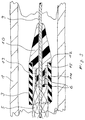
- Fig. 3
- ein Detail eines Längsschnitts durch ein anderes Ausführungsbeispiel eines Katheters nach der Erfindung mit eingespannter Gefässstütze.
- Fig. 1
- a view of a catheter according to the invention with released stent in a schematically indicated vessel
- Fig. 2
- a longitudinal section through a catheter according to the invention with clamped stent
- Fig. 3
- a detail of a longitudinal section through another embodiment of a catheter according to the invention with clamped stent.
In Fig. 1 ist mit 1 idealisiert ein Gefäss z.B. eines menschlichen Körpers dargestellt. Das Gefäss kann Flüssigkeiten, z.B. Blut aufnehmen, es kann aber auch Luft führen, sodass das Gefäss auch eine Luftröhre darstellen kann. In diesem Gefäss liegend ist das bedienungsferne, distale Ende eines Katheters 2 dargestellt. Der Katheter 2 ist an geeigneter Stelle, z.B. an einer Punktion, in das Gefäss eingeführt worden und ist von ausserhalb des Körpers bis zu der dargestellten Stelle im Gefäss vorgeschoben worden. Der Katheter 2 besteht aus einem schlauchförmigen äusseren Katheterschaft 3 und aus einem in diesem liegenden verschieblichen Innenkatheter 4. Der Innenkatheter 4 ist entlang seiner Länge gerade so stramm im Aussenkatheter 3 gelagert, dass eine Längsbewegung des Innenkatheters im Aussenkatheter keine Kräfte erfordert, die keine gefühlvolle Bedienung mehr erlauben. Die Verschiebewege an der proximalen Bedienerseite werden dadurch ohne Hysteresis-Erscheinungen auf das distale Arbeitsende des Innenkatheters 4 übertragen. In der in Fig. 1 dargestellten Lage ist der Innenkatheter 4 aus dem distalen Ende des äusseren Katheterschaftes 3 ein Stück herausgeschoben.In Fig. 1, 1 is idealized, e.g. of a human body. The vessel can contain liquids, e.g. Take up blood, but it can also carry air, so that the vessel can also represent a trachea. The distal end of a
Innen umschliesst der Innenkatheter 4 eng eine Passage für einen Führungsdraht 9.The inside of the
Ein Führungsdraht ist ein Draht, der so flexibel ausgebildet ist, dass Verletzungen des Gefässes durch den Draht beim Vorschieben des Drahtes ausgeschlossen sind. Ein Führungsdraht kommt auf jeden Fall an der Punktionsstelle zum Einsatz, wo das Gefäss punktiert wird. Dort wird nach der "Seldinger-Technik" nach der Punktion mit einer Hohlnadel zunächst durch die Hohlnadel ein Führungsdraht in das Gefäss eingeführt. Über den Führungsdraht wird dann beispielsweise ein Dilator eines Einführ-Besteckes vorgeschoben. Der Dilator weitet die Punktionsstelle auf, zum Beispiel für einen "Einführungsschleuse" genannten Hohlkatheter, der unmittelbar über den Dilator geschoben wird. Wenn der Dilator wieder entfernt ist, können durch die Einführungsschleuse dann die verschiedensten Katheter in das Gefäss eingebracht werden, vor allem auch solche ohne Dilator an ihrem distalen Ende und solche ohne zentrale Passage, ohne zentrales Lumen für einen Führungsdraht.A guidewire is a wire that is designed so flexibly that injuries to the vessel by the wire when the wire is advanced are excluded. A guide wire is definitely used at the puncture site where the vessel is punctured. According to the "Seldinger technique", after the puncture with a hollow needle, a guide wire is first inserted into the vessel through the hollow needle. A dilator of an introducer, for example, is then placed over the guide wire advanced. The dilator expands the puncture site, for example for a hollow catheter called an "introducer sheath", which is pushed directly over the dilator. When the dilator is removed again, a wide variety of catheters can then be introduced into the vessel through the introducer sheath, especially those without a dilator at their distal end and those without a central passage and without a central lumen for a guide wire.
Der Innenkatheter 4 umschliesst die Passage für den Führungsdraht 9 gerade so knapp, dass der Führungsdraht sich noch gut bewegen kann gegenüber dem Innenkatheter. Damit entstehen insgesamt kleine Abmessungen für den Katheter 2. Das ist erwünscht, damit während des Einsatzes der Gefässstütze 5 das im Gefäss 1 strömende Medium möglichst wenig durch den Katheter 2 behindert wird.The
Der Draht 9 kann auch ein Führungsdraht sein, der nicht nur an der Punktionsstelle benutzt wird, sondern der generell zum Einsatz des Katheters 2 im Körper vorgeschoben wird und dem der Katheter 2 dann folgen kann. Es kann aber auch ein Führungsdraht sein, der von einer vorhergehenden Behandlung schon bis zur Behandlungsstelle im Körper vorgeschoben ist und dort noch liegt, beispielsweise von der Behandlung mit einem Ballonkatheter.The
In dem Gefäss 1 ist auch eine Gefässstütze 5 dargestellt. Die Gefässstütze 5 ist aus einem durchlässigen Netz sich überkreuzender steifer Fäden 6 angefertigt. Die Steifigkeit der Fäden 6 und das Verfahren zur Herstellung des Netzes ist so ausgewählt, dass die Gefässstütze 5 bei ihrem Einsatz sich aus einem gespannten Zustand mit kleinem Umfang durch ihre radiale Elastizität aus eigener Kraft aufweitet in einen die Gefässwand stützenden entspannten Zustand mit über die Länge gleichbleibendem grossem Umfang.A
Die steifen Fäden 6, die das Netz bilden, sind schraubenförmig gelegt und überkreuzen sich. Sie haben damit einen bestimmten Winkel zur Längsachse des Gefässes und können z. B. durch ihre Spiralform sich an den jeweils gegenüber liegenden Gefasswänden abstützen. Dadurch wird eine relativ hohe aber vor allem auch eine über die Länge des Fadens und über die Länge der Gefässstütze gleichbleibende Anpresskraft erreicht. Fäden ohne Schraubenform können sich nur an ihren jeweiligen Wurzel- und Endpunkten abstützen, in der Mitte zwischen diesen Abstützungen lässt ihr gegen die Gefässwand gerichteter Stützdruck nach, sobald sie nicht mehr punktförmig sondern über eine bestimmte Gefässlänge an der Gefässwand anliegen.The
In Fig. 2 ist die Gefässstütze 5 in gespanntem Zustand zu sehen. Die Gefässstütze 5 liegt eingespannt auf einen kleinen Umfang zusammengezogen am distalen Ende des schlauchförmigen äusseren Katheterschafts 3 gefangen. Um die Gefässstütze 5 zu öffnen und zu ihrem Einsatz in ihren entspannten Zustand freizugeben in dem sie selbstexpandierend sich aufweitet, sich an die Gefässwand anlegt und diese stützt, wird der äussere Katheterschaft 3 gegenüber dem Innenkatheter 4 zurückgezogen.2, the
Wenn der Aussenkatheter 3 gegenüber dem Innenkatheter zurückgezogen wird, muss der Innenkatheter 4 die im äusseren Katheterschaft 3 an der Innenwand anliegende Gefässstütze 5 an ihrem proximalen Ende axial abstützen, damit eine Relativbewegung zwischen äusserem Katheterschaft 3 und Gefässstütze 5 zustande kommen kann.If the
Besonders in Fig. 1 ist zu sehen, dass die Gefässstütze an ihrem proximalen, bedienungsnahen Ende eingespannt so gesichert ist, dass sie einen durchlässigen Netzkegel 7 bildet. Der Netzkegel 7 ist aus denselben steifen Fäden 6 hergestellt, die auch die Gefässstütze 5 bilden, sodass sich der Kegel 7 zusammen mit der Gefässstütze selbst öffnet. Der Radius dieses Netzkegels 7 steigt stetig zum Radius der Gefässstütze 5 an. An seiner Spitze ist der Netzkegel 7 auf den Aussendurchmesser des Innenkatheters 4 zusammengezogen. Er ist dort durch eine Schicht Bindemittel mit dem Innenkatheter verbunden. Mit Hilfe des Netzkegels 7 ist daher die Gefässstütze 5 an der Verbindungsstelle 8 fest am Innenkatheter 4 verankert.It can be seen particularly in FIG. 1 that the stent is clamped at its proximal, user-friendly end so that it forms a
Der Innenkatheter 4 hat zum Öffnen und Schliessen der Gefässstütze 5 lediglich Druck- und Zugkräfte zu übertragen. Er kann daher in seiner Wandstärke sehr dünn gehalten werden. Das führt ebenfalls zu geringen Aussenabmessungen des Katheters 2, die den Medienstrom im Gefäss wenig behindern.The
Die anderen Enden der steifen Fäden 6 sind, nachdem sie die Gefässstütze 5 gebildet haben, wieder zusammengeführt und sind distal an einer Spitze 10 verankert. Die Fäden bilden dadurch an ihrem distalen Ende einen zweiten, zum ersten spiegelbildlichen Netzkegel 11.The other ends of the
Die Spitze 10, an der die Fäden 6 verankert sind, ist in Fig. 2 im Schnitt dargestellt. In ihrem Inneren lässt sie den Führungsdraht 9 durch. Der Führungsdraht 9 ist frei beweglich gegenüber der Spitze 10, sodass die Spitze 10 beim Öffnen und Schliessen der Gefässstütze ihre Lage zum distalen Ende des Innenkatheters 3 frei verändern kann und dass der Führungsdraht 9 unabhängig vom Katheter 2 bewegt werden kann. Die Passage für den Führungsdraht 9 durch die Spitze 10 zentriert gleichzeitig den Führungsdraht 9 gegenüber dem Katheter 2.The
In der in Fig. 2 dargestellten Lage der Gefässstütze 5, in der der Aussenkatheter 3 die Gefässstütze 5 gespannt vollständig in sich aufnimmt, verschliesst die Spitze 10 die distale Öffnung des Aussenkatheters 3. Sie ist durch einen an der Spitze 10 angeformten Zapfen 15 im Aussenkatheter 3 zentriert. Die Spitze 10 kann zum Verschliessen der distalen Öffnung des Aussenkatheters 3 diesen z.B. ganz ausfüllen. In den gezeigten Ausführungsbeispielen weist sie eine Schulter 12 auf, die zum Abdichten den Aussenkatheter 3 übergreift. Beim Vorschieben des Aussenkatheters 3 schlägt dieser mit seinem distalen Rand an die Schulter 12 an. Der Aussenkatheter 3 wird dadurch zuverlässig abgedichtet und der Arzt hat einen spürbaren Anschlag, als Kontrolle, wann die Gefässstütze vollständig zurückgefaltet ist. An der Stelle der Schulter 12 ist der Durchmesser der Spitze im wesentlichen gleich dem Durchmesser des Aussenkatheters 3. Der Rand der distalen Aussenkatheteröffnung kann dadurch beim Einführen des Katheters 2 in das Gefäss 1 oder beim Passieren von Engstellen im Gefäss 1 nicht hängenbleiben.In the position of the
Die Spitze 10 verjüngt sich zu ihrem distalen Ende und ist distal von der Schulter 12 wie eine Pfeilspitze kegelförmig ausgebildet mit der Passage für den Führungsdraht 9 in der Mitte angeordnet und an der Kegelspitze austretend. Wenn sie den Aussenkatheter 3 verschliesst, erstreckt die Spitze 10 sich soweit nach distal, dass beim Vorschieben des Katheters 2 Verletzungen der Gefässwand durch den Aussenkatheter 3 vermieden werden. Bei der in den Zeichnungen gezeigten Spitze 10 ist diese distale Ausdehnung der Spitze 10 so gross, dass der volle Aussendurchmesser des Katheters 2 nicht stumpfwinklig auf die Gefässwand 1 auftreffen kann. Auf diese Weise wird der Katheter 2 sicher entlang der Gefässlängsachse geleitet und er kann ohne Widerstände vorgeschoben werden. Dabei verhindert der Führungsdraht 9, auf dem die Spitze 10 reitet, eine Verletzung der Gefässwand durch die an der Spitze 10 vorgesehene Kegelspitze.The
Die Spitze 10 kann z.B aus einem röntgenologisch erkennbaren Material hergestellt sein. In Fig. 3 ist ein Ausführungsbeispiel gezeigt, bei dem an der Spitze 10 ein röntgenopaker Ring 13 angebracht ist. Die Spitze 10 selbst muss dann nicht röntgenopak sein. Der Ring 13 ist auf einen am Zapfen 15 ausgebildeten Absatz 14 aufgeschoben. Dieser Absatz 14 dient auch zur Verankerung der Netzfäden 6 an der Spitze 10. Die Fäden 6 sind durch Bindemittel, durch Löten oder durch Schweissen mit dem Ring 13 verbunden.The
Zum Gebrauch liegt die Gefässstütze 5 zunächst gespannt am distalen Ende innerhalb des äusseren Katheterschaftes 3 im Katheter 2. Der Innenkatheter 4 ist zurückgezogen gegenüber dem äusseren Katheterschaft 3 und die Gefässstütze 5 legt sich gegen die Innenwand des äusseren Katheterschaftes 3 wie in Fig. 2. Der Innenkatheter ist soweit zurückgezogen, dass auch das distale Ende der Gefässstütze 5 innerhalb des äusseren Katheterschaftes 3 liegt. Die Spitze 10 verschliesst jetzt die distale Öffnung des Aussenkatheters 3 und dient bei Bedarf als Dilator, als Aufweiter, um z.B. die Punktionsstelle oder eine Engstelle im Gefäss aufzuweiten.For use, the
In diesem Zustand wird der Katheter 2 in das Gefäss 1 eingeführt und in dem Gefäss 1 vorgeschoben. Wenn das distale Ende des Katheters 2 die Behandlungsstelle passiert hat, wird der äussere Katheterschaft 2 gegenüber dem stationär gehaltenen Innenkatheter 4 zurückgezogen. Durch die Verbindung der Gefässstütze 5 mit dem stationär gehaltenen Innenkatheter 4 kommt eine Relativbewegung zwischen Gefässstütze und äusserem Katheterschaft 3 zustande. Dadurch wird die Gefässstütze 5 langsam Stück für Stück, von ihrem distalen Ende her anfangend, freigegeben. Sie tritt aus dem distalen Ende des äusseren Katheterschaftes 3 aus und weitet sich langsam auf in ihren entspannten Zustand, in dem sie sich an die Gefässwand anlegt und sie stützt. Die Gefässstütze wird nun so weit wie erforderlich freigegeben, z.B. bis die Verbindungsstelle 8 aus dem distalen Ende des äusseren Katheterschaftes 3 ausgetreten ist wie in Fig. 1.In this state, the
Soll nun die Gefässstütze 5 wieder aus dem Gefäss 1 entfernt werden, so muss der äussere Katheterschaft 3 gegenüber dem Innenkatheter 4 lediglich wieder vorgeschoben werden. Durch die Verbindung der Gefässstütze 5 mit dem Innenkatheter 4 ergibt sich auch daraus wieder eine Relativbewegung zwischen Gefässstütze und äusserem Katheterschaft 3. Durch die Verbindung der Gefässstütze 5 mit dem Innenkatheter 4 mit Hilfe des Netzkegels 7, dessen Spitze am Innenkatheter 4 befestigt ist, gleitet der Katheterschaft 3 aussen auf dem Netz der Gefässstütze 5 entlang und zwingt dadurch den vom Innenkatheter 4 aus ansteigenden Netzkegel 7 und die daran anschliessende Gefässstütze 5 wieder in ihre gespannte Form zurück in der sie wieder vom Katheterschaft 3 aufgenommen werden kann. Sobald die Gefässstütze sich von der Gefässwand gelöst hat, kann auch der der Innenkatheter 4 gegenüber dem äusseren Katheterschaft 3 zurückgezogen werden. Die Gefässstütze 5 kann auf diese Weise wieder ganz in den äusseren Katheterschaft 5 zurückgezogen werden und der Katheter 2 kann aus dem Gefäss 1 entfernt werden oder der Katheter 2 kann verschoben werden und die GefässStütze 5 kann an einer korrigierten Stelle erneut ausgebracht werden.If the
Ein vorteilhaftes Verfahren, einen Katheter 2 nach der Erfindung herzustellen besteht darin, die konvergierenden Enden der beiden Netzkegel 7,11 der Gefässstütze 5 jeweils durch einen Schrumpfschlauch auf dem Aussendurchmesser des entsprechenden Verankerungsbettes am Innenkatheter 3 bzw. auf der Spitze 10 zusammenzuhalten, während die Netzkegel 7,11 mit dem Innenkatheter 3 bzw. mit der Spitze 10 verbunden werden. Der Schrumpfschlauch wird in seinem Rohzustand in dem er noch einen grossem Durchmesser hat, über die Gefässstütze 5 gezogen. Der Schrumpfschlauch wird dann erwärmt, er zieht sich dadurch zusammen und schnürt damit auch die Gefässstütze 5 ein, die er umgibt. Abmessungen und Material des Schrumpfschlauches sowie die Wärmezufuhr zum Schrumpfschlauch können so ausgewählt werden, dass der Schrumpfschlauch die Gefässstütze 5 auf den Aussendurchmesser des Innenkatheters 4 bzw. den Aussendurchmesser des Absatzes 14 zusammenzieht und dort zusammenhält. In diesem Zustand kann dann die Gefässstütze 5 mit dem Innenkatheter 4 verschweisst werden oder eine vorher angebrachte oder durch Kapillarwirkung unter den Schrumpfschlauch in die Verbindungsstelle 8 hinein wandernde Schicht Bindemittel kann aushärten. Nach diesem Vorgang kann der Schrumpfschlauch wieder entfernt werden, sodass, wie in den Fig. 1 und 2 dargestellt, eine glatte Verbindungsstelle 8 übrig bleibt, die, je nach gewähltem Verfahren, im wesentlichen den Durchmesser des Innenkatheters 4 aufweisen kann.An advantageous method for producing a
Claims (5)
Priority Applications (9)
| Application Number | Priority Date | Filing Date | Title |
|---|---|---|---|
| DE59208138T DE59208138D1 (en) | 1992-10-12 | 1992-10-12 | Catheter with a stent |
| ES92203134T ES2100272T3 (en) | 1992-10-12 | 1992-10-12 | CATHETER WITH A CYLINDRICAL VASCULAR SUPPORT. |
| EP92203134A EP0592726B1 (en) | 1992-10-12 | 1992-10-12 | Catheter with a vessel support |
| AT92203134T ATE149325T1 (en) | 1992-10-12 | 1992-10-12 | CATHETER WITH A VESSEL SUPPORT |
| US08/097,799 US5405380A (en) | 1992-10-12 | 1993-07-27 | Catheter with a vascular support |
| CA002108074A CA2108074C (en) | 1992-10-12 | 1993-10-08 | Catheter with a vascular support |
| AU48930/93A AU654633B2 (en) | 1992-10-12 | 1993-10-11 | Catheter with a vascular support |
| JP5254337A JP2837078B2 (en) | 1992-10-12 | 1993-10-12 | catheter |
| US08/375,591 US5626602A (en) | 1992-10-12 | 1995-01-17 | Catheter with a vascular support |
Applications Claiming Priority (1)
| Application Number | Priority Date | Filing Date | Title |
|---|---|---|---|
| EP92203134A EP0592726B1 (en) | 1992-10-12 | 1992-10-12 | Catheter with a vessel support |
Publications (2)
| Publication Number | Publication Date |
|---|---|
| EP0592726A1 true EP0592726A1 (en) | 1994-04-20 |
| EP0592726B1 EP0592726B1 (en) | 1997-03-05 |
Family
ID=8210962
Family Applications (1)
| Application Number | Title | Priority Date | Filing Date |
|---|---|---|---|
| EP92203134A Expired - Lifetime EP0592726B1 (en) | 1992-10-12 | 1992-10-12 | Catheter with a vessel support |
Country Status (8)
| Country | Link |
|---|---|
| US (2) | US5405380A (en) |
| EP (1) | EP0592726B1 (en) |
| JP (1) | JP2837078B2 (en) |
| AT (1) | ATE149325T1 (en) |
| AU (1) | AU654633B2 (en) |
| CA (1) | CA2108074C (en) |
| DE (1) | DE59208138D1 (en) |
| ES (1) | ES2100272T3 (en) |
Cited By (6)
| Publication number | Priority date | Publication date | Assignee | Title |
|---|---|---|---|---|
| EP0770366A1 (en) * | 1995-10-27 | 1997-05-02 | Hans-Reiner Prof. Dr. Figulla | Device for the application of a vessel support |
| EP1970027A1 (en) * | 2007-03-16 | 2008-09-17 | Medtronic Vascular, Inc. | Vascular fluoroscopic marker |
| WO2012160562A1 (en) * | 2011-05-23 | 2012-11-29 | Nitiloop Ltd. | Deployment mechanism for body vessel insertion devices |
| US10426510B2 (en) | 2012-10-22 | 2019-10-01 | Roxwood Medical, Inc. | Method and apparatus for centering a microcatheter within a vasculature |
| US10596354B2 (en) | 2015-09-25 | 2020-03-24 | Mark Taber | Guide wires, catheters, and guide wire catheter systems and methods |
| US11065028B2 (en) | 2007-06-26 | 2021-07-20 | Roxwood Medical Inc. | Method and apparatus for placing a catheter within a vasculature |
Families Citing this family (108)
| Publication number | Priority date | Publication date | Assignee | Title |
|---|---|---|---|---|
| WO1994023786A1 (en) * | 1993-04-13 | 1994-10-27 | Boston Scientific Corporation | Prosthesis delivery system |
| EP0702535B1 (en) * | 1993-04-13 | 2003-01-08 | Boston Scientific Corporation | Prosthesis delivery system with dilating tip |
| RU2089131C1 (en) * | 1993-12-28 | 1997-09-10 | Сергей Апполонович Пульнев | Stent-expander |
| US5645560A (en) * | 1995-12-15 | 1997-07-08 | Cardiovascular Dynamics, Inc. | Fixed focal balloon for interactive angioplasty and stent implantation |
| US5755708A (en) * | 1994-12-09 | 1998-05-26 | Segal; Jerome | Mechanical apparatus and method for deployment of expandable prosthesis |
| FR2735967B1 (en) * | 1995-06-27 | 1998-03-06 | Perouse Implant Lab | VASCULAR SURGERY TOOL AND ITS USE |
| US6261318B1 (en) | 1995-07-25 | 2001-07-17 | Medstent Inc. | Expandable stent |
| NZ313115A (en) * | 1995-07-25 | 2000-01-28 | Medstent Inc | Expandible stent |
| US6991614B2 (en) | 1995-11-07 | 2006-01-31 | Boston Scientific Scimed, Inc. | Ureteral stent for improved patient comfort |
| EP0775470B1 (en) * | 1995-11-14 | 1999-03-24 | Schneider (Europe) GmbH | Stent delivery device |
| US6077295A (en) | 1996-07-15 | 2000-06-20 | Advanced Cardiovascular Systems, Inc. | Self-expanding stent delivery system |
| US5944726A (en) * | 1996-08-23 | 1999-08-31 | Scimed Life Systems, Inc. | Stent delivery system having stent securement means |
| US6007543A (en) * | 1996-08-23 | 1999-12-28 | Scimed Life Systems, Inc. | Stent delivery system with stent securement means |
| AU739710B2 (en) * | 1996-08-23 | 2001-10-18 | Boston Scientific Limited | Stent delivery system having stent securement apparatus |
| US5980530A (en) * | 1996-08-23 | 1999-11-09 | Scimed Life Systems Inc | Stent delivery system |
| US6077273A (en) * | 1996-08-23 | 2000-06-20 | Scimed Life Systems, Inc. | Catheter support for stent delivery |
| US6123712A (en) | 1996-08-23 | 2000-09-26 | Scimed Life Systems, Inc. | Balloon catheter with stent securement means |
| US6391032B2 (en) | 1996-08-23 | 2002-05-21 | Scimed Life Systems, Inc. | Stent delivery system having stent securement means |
| US6395008B1 (en) | 1996-08-23 | 2002-05-28 | Scimed Life Systems, Inc. | Stent delivery device using stent cups and mounting collars |
| US5968068A (en) * | 1996-09-12 | 1999-10-19 | Baxter International Inc. | Endovascular delivery system |
| US5957974A (en) * | 1997-01-23 | 1999-09-28 | Schneider (Usa) Inc | Stent graft with braided polymeric sleeve |
| US6254633B1 (en) * | 1997-02-12 | 2001-07-03 | Corvita Corporation | Delivery device for a medical device having a constricted region |
| EP1017321B1 (en) | 1997-02-13 | 2004-01-14 | Boston Scientific Limited | Percutaneous and hiatal devices for use in minimally invasive pelvic surgery |
| US5855565A (en) * | 1997-02-21 | 1999-01-05 | Bar-Cohen; Yaniv | Cardiovascular mechanically expanding catheter |
| CA2235911C (en) * | 1997-05-27 | 2003-07-29 | Schneider (Usa) Inc. | Stent and stent-graft for treating branched vessels |
| US5906641A (en) * | 1997-05-27 | 1999-05-25 | Schneider (Usa) Inc | Bifurcated stent graft |
| JP3527619B2 (en) * | 1997-06-25 | 2004-05-17 | ペンタックス株式会社 | Endoscope stent |
| EP0891752B1 (en) * | 1997-07-17 | 2005-01-12 | Schneider (Europe) GmbH | Stent and method for manufacturing such a stent |
| US6517515B1 (en) | 1998-03-04 | 2003-02-11 | Scimed Life Systems, Inc. | Catheter having variable size guide wire lumen |
| US6113579A (en) | 1998-03-04 | 2000-09-05 | Scimed Life Systems, Inc. | Catheter tip designs and methods for improved stent crossing |
| US6511492B1 (en) * | 1998-05-01 | 2003-01-28 | Microvention, Inc. | Embolectomy catheters and methods for treating stroke and other small vessel thromboembolic disorders |
| US6171297B1 (en) | 1998-06-30 | 2001-01-09 | Schneider (Usa) Inc | Radiopaque catheter tip |
| US6332892B1 (en) * | 1999-03-02 | 2001-12-25 | Scimed Life Systems, Inc. | Medical device with one or more helical coils |
| US6445958B1 (en) | 1999-04-15 | 2002-09-03 | Intermedics, Inc. | Steerable coronary sinus defibrillation lead |
| US6458139B1 (en) | 1999-06-21 | 2002-10-01 | Endovascular Technologies, Inc. | Filter/emboli extractor for use in variable sized blood vessels |
| FR2796107B1 (en) * | 1999-07-08 | 2001-09-14 | Fabrication D Accastillage Nor | DEVICE FOR IMMOBILIZING A RAIL ALONG A PROFILE, SUCH AS A BOAT Mast |
| US6689120B1 (en) | 1999-08-06 | 2004-02-10 | Boston Scientific Scimed, Inc. | Reduced profile delivery system |
| US6533806B1 (en) | 1999-10-01 | 2003-03-18 | Scimed Life Systems, Inc. | Balloon yielded delivery system and endovascular graft design for easy deployment |
| US8414543B2 (en) | 1999-10-22 | 2013-04-09 | Rex Medical, L.P. | Rotational thrombectomy wire with blocking device |
| US6280465B1 (en) | 1999-12-30 | 2001-08-28 | Advanced Cardiovascular Systems, Inc. | Apparatus and method for delivering a self-expanding stent on a guide wire |
| US6322586B1 (en) | 2000-01-10 | 2001-11-27 | Scimed Life Systems, Inc. | Catheter tip designs and method of manufacture |
| US6514273B1 (en) | 2000-03-22 | 2003-02-04 | Endovascular Technologies, Inc. | Device for removal of thrombus through physiological adhesion |
| US6589273B1 (en) | 2000-10-02 | 2003-07-08 | Impra, Inc. | Apparatus and method for relining a blood vessel |
| US7226464B2 (en) * | 2001-03-01 | 2007-06-05 | Scimed Life Systems, Inc. | Intravascular filter retrieval device having an actuatable dilator tip |
| US6719804B2 (en) | 2001-04-02 | 2004-04-13 | Scimed Life Systems, Inc. | Medical stent and related methods |
| US7674245B2 (en) | 2001-06-07 | 2010-03-09 | Cardiac Pacemakers, Inc. | Method and apparatus for an adjustable shape guide catheter |
| US6726714B2 (en) * | 2001-08-09 | 2004-04-27 | Scimed Life Systems, Inc. | Stent delivery system |
| US6620202B2 (en) | 2001-10-16 | 2003-09-16 | Scimed Life Systems, Inc. | Medical stent with variable coil and related methods |
| US6755812B2 (en) * | 2001-12-11 | 2004-06-29 | Cardiac Pacemakers, Inc. | Deflectable telescoping guide catheter |
| US7717899B2 (en) * | 2002-01-28 | 2010-05-18 | Cardiac Pacemakers, Inc. | Inner and outer telescoping catheter delivery system |
| US20030145122A1 (en) * | 2002-01-30 | 2003-07-31 | International Business Machines Corporation | Apparatus and method of allowing multiple partitions of a partitioned computer system to use a single network adapter |
| US20040039371A1 (en) * | 2002-08-23 | 2004-02-26 | Bruce Tockman | Coronary vein navigator |
| US7331976B2 (en) * | 2003-04-29 | 2008-02-19 | Rex Medical, L.P. | Distal protection device |
| US7604649B2 (en) * | 2003-04-29 | 2009-10-20 | Rex Medical, L.P. | Distal protection device |
| ES2336324T3 (en) * | 2003-10-17 | 2010-04-12 | Tyco Healthcare Group Lp | DEVICE FOR SURGICAL ACCESS AND MANUFACTURE OF THE SAME. |
| US20060206200A1 (en) * | 2004-05-25 | 2006-09-14 | Chestnut Medical Technologies, Inc. | Flexible vascular occluding device |
| EP2626038B1 (en) | 2004-05-25 | 2016-09-14 | Covidien LP | Flexible vascular occluding device |
| US8617234B2 (en) | 2004-05-25 | 2013-12-31 | Covidien Lp | Flexible vascular occluding device |
| US8628564B2 (en) | 2004-05-25 | 2014-01-14 | Covidien Lp | Methods and apparatus for luminal stenting |
| US8267985B2 (en) | 2005-05-25 | 2012-09-18 | Tyco Healthcare Group Lp | System and method for delivering and deploying an occluding device within a vessel |
| EP2419048A4 (en) | 2004-05-25 | 2014-04-09 | Covidien Lp | Vascular stenting for aneurysms |
| US20050273076A1 (en) * | 2004-06-07 | 2005-12-08 | C.R. Bard, Inc. | Subcutaneous infusion devices |
| US20060074483A1 (en) * | 2004-10-01 | 2006-04-06 | Schrayer Howard L | Method of treatment and devices for the treatment of left ventricular failure |
| US20060253184A1 (en) * | 2005-05-04 | 2006-11-09 | Kurt Amplatz | System for the controlled delivery of stents and grafts |
| US20070118207A1 (en) * | 2005-05-04 | 2007-05-24 | Aga Medical Corporation | System for controlled delivery of stents and grafts |
| WO2007004076A2 (en) | 2005-05-09 | 2007-01-11 | Angiomed Gmbh & Co. Medizintechnik Kg | Implant delevery device |
| CN101180006B (en) | 2005-05-25 | 2010-09-22 | 切斯纳特医药技术公司 | System and method for delivering and deploying and occluding device within a vessel |
| US8273101B2 (en) | 2005-05-25 | 2012-09-25 | Tyco Healthcare Group Lp | System and method for delivering and deploying an occluding device within a vessel |
| US20080058856A1 (en) * | 2005-06-28 | 2008-03-06 | Venkatesh Ramaiah | Non-occluding dilation device |
| WO2007002863A2 (en) * | 2005-06-28 | 2007-01-04 | Venkatesh Ramaiah | Non-occlusive, retrievable dilation system |
| US20080114439A1 (en) * | 2005-06-28 | 2008-05-15 | Venkatesh Ramaiah | Non-occluding dilation device |
| US8685074B2 (en) * | 2005-11-18 | 2014-04-01 | Boston Scientific Scimed, Inc. | Balloon catheter |
| US8152833B2 (en) | 2006-02-22 | 2012-04-10 | Tyco Healthcare Group Lp | Embolic protection systems having radiopaque filter mesh |
| US8246574B2 (en) * | 2006-04-21 | 2012-08-21 | Abbott Laboratories | Support catheter |
| US7927305B2 (en) * | 2006-04-21 | 2011-04-19 | Abbott Laboratories | Systems, methods, and devices for injecting media contrast |
| US7993303B2 (en) * | 2006-04-21 | 2011-08-09 | Abbott Laboratories | Stiffening support catheter and methods for using the same |
| US20070250149A1 (en) * | 2006-04-21 | 2007-10-25 | Abbott Laboratories | Stiffening Support Catheters and Methods for Using the Same |
| US8206370B2 (en) * | 2006-04-21 | 2012-06-26 | Abbott Laboratories | Dual lumen guidewire support catheter |
| US9126020B2 (en) | 2007-06-26 | 2015-09-08 | Roxwood Medical, Inc. | Catheter apparatus with telescoping lumen catheters and its use in methods for treating vasculatures |
| US9358037B2 (en) | 2007-06-26 | 2016-06-07 | Roxwood Medical, Inc. | Method and apparatus for centering a microcatheter within a vasculature |
| US7988646B2 (en) | 2007-06-26 | 2011-08-02 | Mark Taber | Catheter apparatus and methods for treating vasculatures |
| US8313525B2 (en) | 2008-03-18 | 2012-11-20 | Medtronic Ventor Technologies, Ltd. | Valve suturing and implantation procedures |
| WO2009140437A1 (en) | 2008-05-13 | 2009-11-19 | Nfocus Neuromedical, Inc. | Braid implant delivery systems |
| US20100185179A1 (en) * | 2009-01-21 | 2010-07-22 | Abbott Cardiovascular Systems Inc. | Needled cannula with filter device |
| US8784467B2 (en) | 2009-05-15 | 2014-07-22 | Lemaitre Vascular, Inc. | Non-occlusive dilation devices |
| AU2011214063B2 (en) | 2010-02-09 | 2014-02-13 | Medinol Ltd. | Device for recanalization of vessel occlusions using guide wire and method of use |
| AU2011237339B2 (en) | 2010-04-08 | 2014-10-30 | BiO2 Medical, Inc. | Catheter hub |
| US20110319902A1 (en) | 2010-06-26 | 2011-12-29 | Scott Epstein | Catheter delivery system |
| US10751206B2 (en) | 2010-06-26 | 2020-08-25 | Scott M. Epstein | Catheter or stent delivery system |
| US9155647B2 (en) | 2012-07-18 | 2015-10-13 | Covidien Lp | Methods and apparatus for luminal stenting |
| US9114001B2 (en) | 2012-10-30 | 2015-08-25 | Covidien Lp | Systems for attaining a predetermined porosity of a vascular device |
| US9452070B2 (en) | 2012-10-31 | 2016-09-27 | Covidien Lp | Methods and systems for increasing a density of a region of a vascular device |
| US9943427B2 (en) | 2012-11-06 | 2018-04-17 | Covidien Lp | Shaped occluding devices and methods of using the same |
| US9157174B2 (en) | 2013-02-05 | 2015-10-13 | Covidien Lp | Vascular device for aneurysm treatment and providing blood flow into a perforator vessel |
| JP2016538909A (en) | 2013-11-04 | 2016-12-15 | ニティループ・リミテッドNitiloop Ltd. | Microcatheter and tube device |
| US9682216B2 (en) | 2014-12-05 | 2017-06-20 | Anchor Endovascular, Inc. | Anchor device for use with catheters |
| EP3466475B1 (en) * | 2016-06-07 | 2021-04-21 | Terumo Kabushiki Kaisha | Percutaneous catheter and percutaneous catheter assembly |
| EP3484421A1 (en) | 2016-07-13 | 2019-05-22 | Boston Scientific Scimed Inc. | Apparatus and method for maintaining patency in a vessel adjacent to nearby surgery |
| EP3481342B1 (en) | 2016-09-19 | 2020-04-29 | CTI Vascular AG | Catheter system for treating vascular and non-vascular diseases |
| JP6790717B2 (en) * | 2016-10-25 | 2020-11-25 | 株式会社ジェイ・エム・エス | Stent delivery system |
| CN107753163A (en) * | 2017-11-29 | 2018-03-06 | 成都创客之家科技有限公司 | A kind of anti-skidding intravascular stent |
| CN107802385A (en) * | 2017-11-29 | 2018-03-16 | 成都创客之家科技有限公司 | A kind of titanium alloy intravascular stent |
| CN107744415A (en) * | 2017-11-29 | 2018-03-02 | 成都创客之家科技有限公司 | A kind of titanium alloy carries medicine intravascular stent |
| CN107744414A (en) * | 2017-11-29 | 2018-03-02 | 成都创客之家科技有限公司 | A kind of film-coated vascular support |
| CN107669380A (en) * | 2017-11-29 | 2018-02-09 | 成都创客之家科技有限公司 | A kind of drug eluting vascular support |
| CN107802377A (en) * | 2017-11-29 | 2018-03-16 | 成都创客之家科技有限公司 | A kind of titanium alloy film-coated vascular support |
| CN107669381A (en) * | 2017-11-29 | 2018-02-09 | 成都创客之家科技有限公司 | A kind of medicament-release blood vessel stent |
| CN107753149A (en) * | 2017-11-29 | 2018-03-06 | 成都创客之家科技有限公司 | A kind of intravascular stent with developing function |
Citations (7)
| Publication number | Priority date | Publication date | Assignee | Title |
|---|---|---|---|---|
| DE1250058B (en) * | 1960-03-26 | 1967-09-14 | Dr Med Heinrich Hackmann | Indwelling probe for emptying the male urinary bladder |
| US4665918A (en) * | 1986-01-06 | 1987-05-19 | Garza Gilbert A | Prosthesis system and method |
| EP0321912A1 (en) * | 1987-12-18 | 1989-06-28 | Gerard L Delsanti | Removable endo-arterial devices intended to repair detachments in arterial walls |
| EP0408245A1 (en) * | 1989-07-13 | 1991-01-16 | American Medical Systems, Inc. | Stent placement instrument |
| EP0418677A1 (en) * | 1989-09-08 | 1991-03-27 | Advanced Cardiovascular Systems, Inc. | A steerable vascular catheter for maintaining the patency of a blood vessel |
| EP0433447A1 (en) * | 1987-08-13 | 1991-06-26 | Terumo Kabushiki Kaisha | Catheter |
| US5071407A (en) * | 1990-04-12 | 1991-12-10 | Schneider (U.S.A.) Inc. | Radially expandable fixation member |
Family Cites Families (21)
| Publication number | Priority date | Publication date | Assignee | Title |
|---|---|---|---|---|
| SE445884B (en) * | 1982-04-30 | 1986-07-28 | Medinvent Sa | DEVICE FOR IMPLANTATION OF A RODFORM PROTECTION |
| IT1186142B (en) * | 1984-12-05 | 1987-11-18 | Medinvent Sa | TRANSLUMINAL IMPLANTATION DEVICE |
| SE454482B (en) * | 1986-09-30 | 1988-05-09 | Medinvent Sa | DEVICE FOR IMPLANTATION |
| SE455834B (en) * | 1986-10-31 | 1988-08-15 | Medinvent Sa | DEVICE FOR TRANSLUMINAL IMPLANTATION OF A PRINCIPLE RODFORMALLY RADIALLY EXPANDABLE PROSTHESIS |
| EP0380668B1 (en) * | 1987-10-08 | 1996-12-27 | Terumo Kabushiki Kaisha | Instrument and apparatus for securing inner diameter of lumen of tubular organ |
| US4885003A (en) * | 1988-07-25 | 1989-12-05 | Cordis Corporation | Double mesh balloon catheter device |
| US4921484A (en) * | 1988-07-25 | 1990-05-01 | Cordis Corporation | Mesh balloon catheter device |
| SE8803444D0 (en) * | 1988-09-28 | 1988-09-28 | Medinvent Sa | A DEVICE FOR TRANSLUMINAL IMPLANTATION OR EXTRACTION |
| US4950227A (en) * | 1988-11-07 | 1990-08-21 | Boston Scientific Corporation | Stent delivery system |
| US5180368A (en) * | 1989-09-08 | 1993-01-19 | Advanced Cardiovascular Systems, Inc. | Rapidly exchangeable and expandable cage catheter for repairing damaged blood vessels |
| US5034001A (en) * | 1989-09-08 | 1991-07-23 | Advanced Cardiovascular Systems, Inc. | Method of repairing a damaged blood vessel with an expandable cage catheter |
| US5035706A (en) * | 1989-10-17 | 1991-07-30 | Cook Incorporated | Percutaneous stent and method for retrieval thereof |
| GB2238245B (en) * | 1989-11-24 | 1994-04-20 | Martin Terry Rothman | Catheters |
| US5108416A (en) * | 1990-02-13 | 1992-04-28 | C. R. Bard, Inc. | Stent introducer system |
| US5221261A (en) * | 1990-04-12 | 1993-06-22 | Schneider (Usa) Inc. | Radially expandable fixation member |
| US5158548A (en) * | 1990-04-25 | 1992-10-27 | Advanced Cardiovascular Systems, Inc. | Method and system for stent delivery |
| US5449372A (en) * | 1990-10-09 | 1995-09-12 | Scimed Lifesystems, Inc. | Temporary stent and methods for use and manufacture |
| US5190058A (en) * | 1991-05-22 | 1993-03-02 | Medtronic, Inc. | Method of using a temporary stent catheter |
| US5192297A (en) * | 1991-12-31 | 1993-03-09 | Medtronic, Inc. | Apparatus and method for placement and implantation of a stent |
| ATE135900T1 (en) * | 1992-02-03 | 1996-04-15 | Schneider Europ Ag | CATHETER WITH A VESSEL SUPPORT |
| US5201757A (en) * | 1992-04-03 | 1993-04-13 | Schneider (Usa) Inc. | Medial region deployment of radially self-expanding stents |
-
1992
- 1992-10-12 EP EP92203134A patent/EP0592726B1/en not_active Expired - Lifetime
- 1992-10-12 ES ES92203134T patent/ES2100272T3/en not_active Expired - Lifetime
- 1992-10-12 DE DE59208138T patent/DE59208138D1/en not_active Expired - Lifetime
- 1992-10-12 AT AT92203134T patent/ATE149325T1/en not_active IP Right Cessation
-
1993
- 1993-07-27 US US08/097,799 patent/US5405380A/en not_active Expired - Lifetime
- 1993-10-08 CA CA002108074A patent/CA2108074C/en not_active Expired - Fee Related
- 1993-10-11 AU AU48930/93A patent/AU654633B2/en not_active Ceased
- 1993-10-12 JP JP5254337A patent/JP2837078B2/en not_active Expired - Fee Related
-
1995
- 1995-01-17 US US08/375,591 patent/US5626602A/en not_active Expired - Lifetime
Patent Citations (7)
| Publication number | Priority date | Publication date | Assignee | Title |
|---|---|---|---|---|
| DE1250058B (en) * | 1960-03-26 | 1967-09-14 | Dr Med Heinrich Hackmann | Indwelling probe for emptying the male urinary bladder |
| US4665918A (en) * | 1986-01-06 | 1987-05-19 | Garza Gilbert A | Prosthesis system and method |
| EP0433447A1 (en) * | 1987-08-13 | 1991-06-26 | Terumo Kabushiki Kaisha | Catheter |
| EP0321912A1 (en) * | 1987-12-18 | 1989-06-28 | Gerard L Delsanti | Removable endo-arterial devices intended to repair detachments in arterial walls |
| EP0408245A1 (en) * | 1989-07-13 | 1991-01-16 | American Medical Systems, Inc. | Stent placement instrument |
| EP0418677A1 (en) * | 1989-09-08 | 1991-03-27 | Advanced Cardiovascular Systems, Inc. | A steerable vascular catheter for maintaining the patency of a blood vessel |
| US5071407A (en) * | 1990-04-12 | 1991-12-10 | Schneider (U.S.A.) Inc. | Radially expandable fixation member |
Cited By (8)
| Publication number | Priority date | Publication date | Assignee | Title |
|---|---|---|---|---|
| EP0770366A1 (en) * | 1995-10-27 | 1997-05-02 | Hans-Reiner Prof. Dr. Figulla | Device for the application of a vessel support |
| EP1970027A1 (en) * | 2007-03-16 | 2008-09-17 | Medtronic Vascular, Inc. | Vascular fluoroscopic marker |
| US7967807B2 (en) | 2007-03-16 | 2011-06-28 | Medtronic Vascular, Inc. | Vascular fluoroscopic marker |
| US11065028B2 (en) | 2007-06-26 | 2021-07-20 | Roxwood Medical Inc. | Method and apparatus for placing a catheter within a vasculature |
| WO2012160562A1 (en) * | 2011-05-23 | 2012-11-29 | Nitiloop Ltd. | Deployment mechanism for body vessel insertion devices |
| US10039896B2 (en) | 2011-05-23 | 2018-08-07 | Nitiloop Ltd. | Deployment mechanism for body vessel insertion devices |
| US10426510B2 (en) | 2012-10-22 | 2019-10-01 | Roxwood Medical, Inc. | Method and apparatus for centering a microcatheter within a vasculature |
| US10596354B2 (en) | 2015-09-25 | 2020-03-24 | Mark Taber | Guide wires, catheters, and guide wire catheter systems and methods |
Also Published As
| Publication number | Publication date |
|---|---|
| CA2108074A1 (en) | 1994-04-13 |
| AU654633B2 (en) | 1994-11-10 |
| JPH06197975A (en) | 1994-07-19 |
| CA2108074C (en) | 1996-08-20 |
| ATE149325T1 (en) | 1997-03-15 |
| DE59208138D1 (en) | 1997-04-10 |
| ES2100272T3 (en) | 1997-06-16 |
| US5626602A (en) | 1997-05-06 |
| AU4893093A (en) | 1994-04-28 |
| US5405380A (en) | 1995-04-11 |
| EP0592726B1 (en) | 1997-03-05 |
| JP2837078B2 (en) | 1998-12-14 |
Similar Documents
| Publication | Publication Date | Title |
|---|---|---|
| EP0592726B1 (en) | Catheter with a vessel support | |
| EP0554579B1 (en) | Catheter with vessel support | |
| DE60226354T2 (en) | Guidewire device for total occlusion | |
| DE69925627T2 (en) | MINIMAL INVASIVE REVASCULARIZATION APPARATUS | |
| DE69533356T2 (en) | DEVICE FOR INSERTING AND UNFOLDING INTRALUMINAL DEVICES | |
| DE10334868B4 (en) | Implantable device as a replacement organ valve, its manufacturing process and basic body and membrane element for it | |
| DE60214973T3 (en) | DEVICE FOR IMPLANTING A STENT WITH LIQUID DISPENSER | |
| DE69532567T2 (en) | Intraluminal branched multi-capsule transplantation system | |
| DE69533730T2 (en) | QUICK REPLACEMENT FEEDING CATHETER SYSTEM | |
| DE69722940T2 (en) | INTRAVASCULAR PROSTHESIS | |
| DE69828634T2 (en) | GUIDE WIRE FOR TEMPORARY BLOOD FILTERS | |
| DE60213352T2 (en) | Device for a temporary intraluminal protection | |
| EP0627201B1 (en) | Device for releasing a self-expanding endoprosthesis | |
| EP1848375B1 (en) | Catheter for the transvascular implantation of prosthetic heart valves | |
| DE60035791T2 (en) | INTRODUCING DEVICE FOR AN IMPLANT | |
| DE69434819T2 (en) | INSERTING A PROSTHESIS | |
| AT392733B (en) | DEVICE FOR TREATING BLOOD VESSELS OR THE LIKE. | |
| DE60110371T2 (en) | DEVICE FOR INTRODUCING AN INTRALUMINARY PROSTHESIS | |
| DE60034918T2 (en) | Fast replacement catheter for self-expanding stent | |
| DE69732411T2 (en) | Repair of body vessels by prostheses | |
| DE60119142T2 (en) | ENDOLUMINAL APPLIED VASCULAR TRANSPLANT | |
| DE60221108T2 (en) | Temporary intraluminal filter | |
| DE69924100T2 (en) | DEVICE FOR REVERSIBLE INSERTION OF AN ENDOPROTHESIS | |
| EP1336392A1 (en) | Body vessel support and catheter system | |
| EP0536610A1 (en) | Stenosis dilatation device |
Legal Events
| Date | Code | Title | Description |
|---|---|---|---|
| PUAI | Public reference made under article 153(3) epc to a published international application that has entered the european phase |
Free format text: ORIGINAL CODE: 0009012 |
|
| 17P | Request for examination filed |
Effective date: 19921027 |
|
| AK | Designated contracting states |
Kind code of ref document: A1 Designated state(s): AT BE CH DE ES FR GB IE IT LI NL SE |
|
| 17Q | First examination report despatched |
Effective date: 19950322 |
|
| GRAH | Despatch of communication of intention to grant a patent |
Free format text: ORIGINAL CODE: EPIDOS IGRA |
|
| GRAH | Despatch of communication of intention to grant a patent |
Free format text: ORIGINAL CODE: EPIDOS IGRA |
|
| GRAA | (expected) grant |
Free format text: ORIGINAL CODE: 0009210 |
|
| AK | Designated contracting states |
Kind code of ref document: B1 Designated state(s): AT BE CH DE ES FR GB IE IT LI NL SE |
|
| REF | Corresponds to: |
Ref document number: 149325 Country of ref document: AT Date of ref document: 19970315 Kind code of ref document: T |
|
| REG | Reference to a national code |
Ref country code: CH Ref legal event code: EP |
|
| REF | Corresponds to: |
Ref document number: 59208138 Country of ref document: DE Date of ref document: 19970410 |
|
| REG | Reference to a national code |
Ref country code: CH Ref legal event code: NV Representative=s name: A. MISRACHI |
|
| GBT | Gb: translation of ep patent filed (gb section 77(6)(a)/1977) |
Effective date: 19970416 |
|
| REG | Reference to a national code |
Ref country code: IE Ref legal event code: FG4D Free format text: 72337 |
|
| ITF | It: translation for a ep patent filed |
Owner name: STUDIO APRA' BREVETTI |
|
| ET | Fr: translation filed | ||
| REG | Reference to a national code |
Ref country code: ES Ref legal event code: FG2A Ref document number: 2100272 Country of ref document: ES Kind code of ref document: T3 |
|
| PLBE | No opposition filed within time limit |
Free format text: ORIGINAL CODE: 0009261 |
|
| STAA | Information on the status of an ep patent application or granted ep patent |
Free format text: STATUS: NO OPPOSITION FILED WITHIN TIME LIMIT |
|
| 26N | No opposition filed | ||
| PGFP | Annual fee paid to national office [announced via postgrant information from national office to epo] |
Ref country code: SE Payment date: 19990830 Year of fee payment: 8 |
|
| PGFP | Annual fee paid to national office [announced via postgrant information from national office to epo] |
Ref country code: AT Payment date: 19990831 Year of fee payment: 8 |
|
| PGFP | Annual fee paid to national office [announced via postgrant information from national office to epo] |
Ref country code: BE Payment date: 19990913 Year of fee payment: 8 |
|
| PGFP | Annual fee paid to national office [announced via postgrant information from national office to epo] |
Ref country code: CH Payment date: 19990916 Year of fee payment: 8 |
|
| PGFP | Annual fee paid to national office [announced via postgrant information from national office to epo] |
Ref country code: ES Payment date: 19991015 Year of fee payment: 8 |
|
| PG25 | Lapsed in a contracting state [announced via postgrant information from national office to epo] |
Ref country code: AT Free format text: LAPSE BECAUSE OF NON-PAYMENT OF DUE FEES Effective date: 20001012 |
|
| PG25 | Lapsed in a contracting state [announced via postgrant information from national office to epo] |
Ref country code: ES Free format text: LAPSE BECAUSE OF NON-PAYMENT OF DUE FEES Effective date: 20001013 |
|
| PG25 | Lapsed in a contracting state [announced via postgrant information from national office to epo] |
Ref country code: SE Free format text: THE PATENT HAS BEEN ANNULLED BY A DECISION OF A NATIONAL AUTHORITY Effective date: 20001030 |
|
| PG25 | Lapsed in a contracting state [announced via postgrant information from national office to epo] |
Ref country code: LI Free format text: LAPSE BECAUSE OF NON-PAYMENT OF DUE FEES Effective date: 20001031 Ref country code: BE Free format text: LAPSE BECAUSE OF NON-PAYMENT OF DUE FEES Effective date: 20001031 Ref country code: CH Free format text: LAPSE BECAUSE OF NON-PAYMENT OF DUE FEES Effective date: 20001031 |
|
| BERE | Be: lapsed |
Owner name: SCHNEIDER (EUROPE) A.G. Effective date: 20001031 |
|
| REG | Reference to a national code |
Ref country code: CH Ref legal event code: PL |
|
| EUG | Se: european patent has lapsed |
Ref document number: 92203134.9 |
|
| REG | Reference to a national code |
Ref country code: GB Ref legal event code: IF02 |
|
| PGFP | Annual fee paid to national office [announced via postgrant information from national office to epo] |
Ref country code: GB Payment date: 20020913 Year of fee payment: 11 |
|
| PGFP | Annual fee paid to national office [announced via postgrant information from national office to epo] |
Ref country code: FR Payment date: 20021003 Year of fee payment: 11 |
|
| PGFP | Annual fee paid to national office [announced via postgrant information from national office to epo] |
Ref country code: IE Payment date: 20021023 Year of fee payment: 11 |
|
| PG25 | Lapsed in a contracting state [announced via postgrant information from national office to epo] |
Ref country code: GB Free format text: LAPSE BECAUSE OF NON-PAYMENT OF DUE FEES Effective date: 20031012 |
|
| PG25 | Lapsed in a contracting state [announced via postgrant information from national office to epo] |
Ref country code: IE Free format text: LAPSE BECAUSE OF NON-PAYMENT OF DUE FEES Effective date: 20031013 |
|
| REG | Reference to a national code |
Ref country code: ES Ref legal event code: FD2A Effective date: 20011113 |
|
| GBPC | Gb: european patent ceased through non-payment of renewal fee |
Effective date: 20031012 |
|
| PG25 | Lapsed in a contracting state [announced via postgrant information from national office to epo] |
Ref country code: FR Free format text: LAPSE BECAUSE OF NON-PAYMENT OF DUE FEES Effective date: 20040630 |
|
| REG | Reference to a national code |
Ref country code: IE Ref legal event code: MM4A |
|
| REG | Reference to a national code |
Ref country code: FR Ref legal event code: ST |
|
| PG25 | Lapsed in a contracting state [announced via postgrant information from national office to epo] |
Ref country code: IT Free format text: LAPSE BECAUSE OF NON-PAYMENT OF DUE FEES;WARNING: LAPSES OF ITALIAN PATENTS WITH EFFECTIVE DATE BEFORE 2007 MAY HAVE OCCURRED AT ANY TIME BEFORE 2007. THE CORRECT EFFECTIVE DATE MAY BE DIFFERENT FROM THE ONE RECORDED. Effective date: 20051012 |
|
| PGFP | Annual fee paid to national office [announced via postgrant information from national office to epo] |
Ref country code: DE Payment date: 20091030 Year of fee payment: 18 |
|
| PGFP | Annual fee paid to national office [announced via postgrant information from national office to epo] |
Ref country code: NL Payment date: 20091009 Year of fee payment: 18 |
|
| REG | Reference to a national code |
Ref country code: NL Ref legal event code: V1 Effective date: 20110501 |
|
| PG25 | Lapsed in a contracting state [announced via postgrant information from national office to epo] |
Ref country code: NL Free format text: LAPSE BECAUSE OF NON-PAYMENT OF DUE FEES Effective date: 20110501 |
|
| REG | Reference to a national code |
Ref country code: DE Ref legal event code: R119 Ref document number: 59208138 Country of ref document: DE Effective date: 20110502 |
|
| PG25 | Lapsed in a contracting state [announced via postgrant information from national office to epo] |
Ref country code: DE Free format text: LAPSE BECAUSE OF NON-PAYMENT OF DUE FEES Effective date: 20110502 |