EP0592719B1 - Ball for ball game - Google Patents
Ball for ball game Download PDFInfo
- Publication number
- EP0592719B1 EP0592719B1 EP92117713A EP92117713A EP0592719B1 EP 0592719 B1 EP0592719 B1 EP 0592719B1 EP 92117713 A EP92117713 A EP 92117713A EP 92117713 A EP92117713 A EP 92117713A EP 0592719 B1 EP0592719 B1 EP 0592719B1
- Authority
- EP
- European Patent Office
- Prior art keywords
- ball
- mold
- valve
- base body
- hemispherical hollow
- Prior art date
- Legal status (The legal status is an assumption and is not a legal conclusion. Google has not performed a legal analysis and makes no representation as to the accuracy of the status listed.)
- Expired - Lifetime
Links
Images


Classifications
-
- A—HUMAN NECESSITIES
- A63—SPORTS; GAMES; AMUSEMENTS
- A63B—APPARATUS FOR PHYSICAL TRAINING, GYMNASTICS, SWIMMING, CLIMBING, OR FENCING; BALL GAMES; TRAINING EQUIPMENT
- A63B41/00—Hollow inflatable balls
-
- A—HUMAN NECESSITIES
- A63—SPORTS; GAMES; AMUSEMENTS
- A63B—APPARATUS FOR PHYSICAL TRAINING, GYMNASTICS, SWIMMING, CLIMBING, OR FENCING; BALL GAMES; TRAINING EQUIPMENT
- A63B45/00—Apparatus or methods for manufacturing balls
-
- B—PERFORMING OPERATIONS; TRANSPORTING
- B29—WORKING OF PLASTICS; WORKING OF SUBSTANCES IN A PLASTIC STATE IN GENERAL
- B29C—SHAPING OR JOINING OF PLASTICS; SHAPING OF MATERIAL IN A PLASTIC STATE, NOT OTHERWISE PROVIDED FOR; AFTER-TREATMENT OF THE SHAPED PRODUCTS, e.g. REPAIRING
- B29C45/00—Injection moulding, i.e. forcing the required volume of moulding material through a nozzle into a closed mould; Apparatus therefor
- B29C45/17—Component parts, details or accessories; Auxiliary operations
- B29C45/40—Removing or ejecting moulded articles
- B29C45/44—Removing or ejecting moulded articles for undercut articles
- B29C45/4407—Removing or ejecting moulded articles for undercut articles by flexible movement of undercut portions of the articles
-
- A—HUMAN NECESSITIES
- A63—SPORTS; GAMES; AMUSEMENTS
- A63B—APPARATUS FOR PHYSICAL TRAINING, GYMNASTICS, SWIMMING, CLIMBING, OR FENCING; BALL GAMES; TRAINING EQUIPMENT
- A63B2243/00—Specific ball sports not provided for in A63B2102/00 - A63B2102/38
- A63B2243/0025—Football
-
- Y—GENERAL TAGGING OF NEW TECHNOLOGICAL DEVELOPMENTS; GENERAL TAGGING OF CROSS-SECTIONAL TECHNOLOGIES SPANNING OVER SEVERAL SECTIONS OF THE IPC; TECHNICAL SUBJECTS COVERED BY FORMER USPC CROSS-REFERENCE ART COLLECTIONS [XRACs] AND DIGESTS
- Y10—TECHNICAL SUBJECTS COVERED BY FORMER USPC
- Y10S—TECHNICAL SUBJECTS COVERED BY FORMER USPC CROSS-REFERENCE ART COLLECTIONS [XRACs] AND DIGESTS
- Y10S425/00—Plastic article or earthenware shaping or treating: apparatus
- Y10S425/01—Core positioning
Definitions
- the present invention relates to a ball for ball games such as a soccer ball, which contains compressed air sealed therein, hits player's body directly or kicked with his leg, and so forth.
- the present invention also relates to a mold for forming a base body of such a ball.
- the base body of the most conventional type comprises a tube of butyl rubber for containing and sealing compressed air and a thread wound reinforcement layer formed by winding the surface of the tube with a thread of nylon or the like having a length of about 3000 m along endless track.
- a base body is bonded at its surface with a plurality of leather panels, with intervention of a thin rubber layer.
- the whole base body thereof is covered with twelve pentagonal leather panels and twenty hexagonal leather panels.
- the base body of the above arrangement is formed with many production steps, taking a long time.
- a method for integrally forming a base body of ball by rotational molding of a thermoplastic elastomer Japanese Unexamined Patent Publication No. 4634/1978.
- thermoplastic elastomer or specifically a polyester elastomer is molded or formed into a base body of the ball.
- a commercially available elastomer usually has an extremely wide range of 10 % tensile stress from 1 to 200 kg/cm2. It is extremely difficult to fabricate a ball for practical use without limiting such stress of the base body thereof. This is because insufficient tensile stress would cause the ball to entirely expand with elapse of time due to the internal pressure of compressed air. In contrast, too much tensile stress would cause little deformation of the ball upon impact and hence bring a pain to a player when hitted with the ball. In addition the tensile stress out of a predetermined range results in an undesired impact resilience and hence improper bounce.
- a base body is formed of a spherical hollow body which is composed of two hemispherical hollow bodies obtained by injection-molding a thermoplastic elastomer and bonded together, as disclosed in Japanese Unexamined Utility Model Publication No. 88567/1991.
- one hemispherical hollow body is molded integrally with a valve at the center thereof.
- Fig. 12 illustrates a mold for forming such valve-integrated hemispherical hollow body.
- Denoted by numerals 51 and 52 are an upper mold and a lower mold, respectively, between which a cavity 53 for forming one hemispherical hollow body is defined.
- a core 54 is provided for forming a valve and integrally formed with the upper mold 51.
- a runner 55 for injection molding is extending centrally through the core 54.
- Denoted by numeral 56 is a valve-forming cavity, by numeral 57 a recessed portion defined in the lower mold 52 at a position corresponding to the exit of the runner 55 for facilitating the flow of molten thermoplastic elastomer from the runner 55 to the cavity 56.
- the mold structure shown in Fig. 12 is developed for ease of releasing a molded hemispherical hollow body from the upper mold 51 having the core 54.
- a large-diameter portion of the core 54 needs to be relatively large for maintaining a valve rubber, but if it is too large, the hemispherical hollow body is hard to be released. Accordingly, the diameter of the large-diameter portion is restricted in view of the difficulty of releasing. This results in weakened force for maintaining the valve rubber and insufficient air-sealing.
- the present invention has been achieved in view of the above-mentioned circumstances. More specifically, the present inventors have found, as a result of various experiments on the requirements for a ball, wherein base bodies were formed using various thermoplastic elastomers, the fact that if the tensile stress to which the inventors' attention is directed is set within a given range, various properties of a ball such as shock-absorptivity, shape-maintaining property, impact resilience and the like can be set within appropriate ranges. Thus, a first invention of the present invention has been achieved.
- a second invention of the present invention is designed so that after molding of a hemispherical hollow body, the body can be automatically released without leaving an unnecessary mass of resin on the body.
- numeral 1 and 2 denote two hemispherical hollow bodies, respectively which are formed from a thermoplastic elastomer by injection molding to be described later.
- One hemispherical hollow body 1 is integrally formed at the center thereof with a valve 3.
- the two hemispherical hollow bodies 1 and 2 are bonded together at peripheral edges thereof by fusion to form a base body 4.
- the 10 % tensile stress of the thermoplastic elastomer forming the base body 4 and valve 3 needs to be set within the range of 30 to 190 kg/cm2. If the value does not reach 30 kg/cm2, the ball is expanded and deformed by the internal pressure and hence cannot maintain its designed size. On the contrary, the value exceeding 190 kg/cm2 results in too small deformation upon impact and hence makes the touch of the ball hard. Therefore, the player comes to feel a pain at the body, hand, leg or the like when hitted by such ball. In addition too large the value results in unsuitable bounce for controlling the ball; hence it is impossible to realize a ball suitable for games.
- the impact resilience JIS K 6301
- the impact resilience can be set within the range of 40 to 80 %, which range assures a suitable bounce for soccer, basket ball, volley ball and the like.
- thermoplastic polyurethane PARABLENE (trademark, a product of NIPPON POLY URETHANE CO., LTD.), TAKERAKKU (trademark, a product of TAKEDA-BADISCH URETHANE INDUSTRIES LTD.), TOYOBO URETHANE (a product of TOYOBO CO., LTD.), Desmopan (trademark, a product of BAYEL CO., LTD.), MIRACTRAN (trademark, a product of NIPPON MIRACTRAN CO., LTD.), ELASTOLLAN (trademark, a product of NIPPON ELASTOLLAN INDUSTRIES LTD.), Pandex (trademark, a product of DAINIPPON INK & CHEMICALS, INC.), MOBILON (trademark, a product of NISSHINBO INDUSTRIES, INC.).
- polyester-series thermoplastic elastomer PELPRENE (trademark, a product of TOYOBO CO., LTD.), HYTREL (trademark, a product of DU PONT-TORAY CO., LTD.), GRILUX E (trademark; a product of DAINIPPON INK & CHEMICALS, INC.).
- polyamide-series thermoplastic elastomer PEBAX (trademark, a product of TORAY INDUSTRIES INC.), GRILUX A (trademark, a product of DAINIPPON INK & CHEMICALS, INC).
- thermoplastic elastomer a product of SUMITOMO CHEMICAL CO., LTD.
- MILASTOMER trademark, a product of MITSUI PETROCHEMICAL LTD.
- SANTOPRENE trademark, a product of AES JAPAN LTD.
- TAFMER trademark, a product of MITSUI PETROCHEMICAL LTD.
- styrene-series thermoplastic elastomer TUFPRENE (trademark, a product of ASAHI CHEMICAL INDUSTRIES CO., LTD.), KRATON (trademark, a product of SHELL JAPAN LTD.), JSR TR (JAPAN SYNTHETIC RUBBER CO., LTD.).
- polyvinylchloride-series thermoplastic elastomer SUMIFLEX (trademark, a product of SUMITOMO BAKELITE CO., LTD.), SANPRENE (trademark, a product of MITSUBISHI KASEI VINYL CO.).
- JSR RB polybutadiene-series thermoplastic elastomer
- soft nylon GRILUX N trademark, a product of DAINIPPON INK & CHEMICALS, INC.
- the base body 4 is bonded, at the surface thereof, with leather or synthetic leather panels 5,5 hexagonally and pentagonally cut. Side edges of each of the panels 5,5 are obliquely cut to form grooves 6,6 drawing boundaries with adjacent panels 5,5.
- Numeral 7 denotes a valve rubber as a component of the valve 3, which is removably mounted into the valve 3 and inserted with a needle of air injector to permit compressed air to be injected into the base body 4.
- a base body of a soccer ball of size 5 was formed to 1.3 mm thick using as the thermoplastic elastomer material a polyester-series elastomer, or specifically PELPRENE (trademark, a product of TOYOBO CO., LTD.).
- the base body was then bonded with leather panels and injected with compressed air to an internal pressure of 0.6 kg/cm2, which valve was as same as that for a common soccer ball.
- the 10 % tensile stress and impact resilience of the resulting ball were 74 kg/cm2 and 50.4 %, respectively and suitable for a soccer ball.
- the impact or shock caused when the ball hitted a player was almost the same as that caused by a conventional ball of a thread wound structure; accordingly, the player felt little pain.
- numerals 1 and 2 denote the above-mentioned two hemispherical hollow bodies, respectively which are formed from the thermoplastic elastomer by injection molding. These two hemispherical hollow bodies 1 and 2 are bonded together at their peripheral edges by heat fusion, to form the base body 4.
- a valve 3 is formed integrally with the hemispherical hollow body 1, inwardly projected at the center of the body 1, and has a valve rubber insertion hole 14.
- the valve rubber insertion hole 14 comprises an outside and small-diameter portion 15 situated on the surface-side of the ball and having a diameter of about 6 to 8 mm and a length of about 3 to 5 mm, an intermediate and large-diameter portion 16 having a diameter of about 9.5 to 11.5 mm and a length of about 3 to 4.5 mm, and an inside and small-diameter portion 17 having a diameter of about 5 to 6 mm and a length of about 9 to 10 mm.
- a slit 18 is provided in the outside and small-diameter portion 15 for facilitating withdrawal of a second valve mold 27 (shown in Fig. 2).
- a valve rubber 7 is shaped as substantially the same as or slighty larger than the contour of the valve rubber insertion hole 14.
- Denoted by numeral 20 is a small aperture formed centrally of the valve rubber 7, for insertion of a needle of air injector, and by numeral 21 is a cut.
- denoted by numerals 22, 22, 22 are small circular traces formed by cutting off the end portions of resin gates.
- a first mold having a hemispherical convex denoted by numeral 23 is a first mold having a hemispherical convex
- the cavity 25 is set to have a diameter of 21.5 cm at the peripheral end thereof and a thickness of 1.0 mm.
- Numeral 26 denotes a first valve mold disposed centrally of the surface of hemispherical convex of the first mold 23 and removable in the direction toward the center the hemisphere, which valve mold is for forming the outer form of the valve 3 and the inside and small-diameter portion 17 of the valve rubber insertion hole 14.
- Numeral 27 denotes a second valve mold disposed contrally of the surface of hemispherical concave of the second mold 24 and removable in the direction outwardly from the second mold 24, i.e., in the direction toward the side opposite to the first mold 23, which valve mold is for forming the intermediate and large-diameter portion 16 and outside and small-diameter portion 15 of the valve rubber insertion hole 14.
- a cavity 28 for forming the valve 3 is defined between the first and second valve molds 26 and 27.
- Three thin-plate projections 29 are provided in the outside and small-diameter portion 15 associated with the second valve mold 27, for forming the slit 18.
- Three runners 30 are formed in the second valve mold 27 for injecting heat-plasticized or molten thermoplastic elastomer into the cavity 25 through gates 31 disposed in the periphery of the outside and small-diameter portion 15 of the valve rubber insertion hole 14.
- Numeral 32 denotes a sprue mold disposed outside the second mold 24 and second valve mold 27, for providing a sprue 33 to be contacted with a nozzle of a resin-injector (not shown), through which sprue 33 resin or thermoplastic elastomer is supplied to the runners 30.
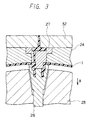
- the first mold 23 is moved in the direction indicated by arrow a, to be released from the first valve mold 26 and the hemispherical hollow body 1 (see Fig. 3).
- the first valve mold 26 is moved in the direction indicated by arrow b, to be released from the hemispherical hollow body 1 (see Fig. 4).
- the sprue mold 32 is moved outwardly or in the direction indicated by arrow c, to be released from the second mold 24.
- the resin in the tip end portion of the runner 30 is cut at the gate 31, and the resin in the sprue 33 and in the runner 30 is moved upwardly in the drawing, together with the sprue mold 32 (see Fig. 5).
- the second valve mold 27 is made to move in the direction indicated by arrow d in Fig. 6, to be released from the second mold 24.
- a diametrically-enlarged portion 34 at the lower end of the second valve mold 27 is caught by the resin in the outside and small-diameter portion 15, the presence of the resin in the slit 18 enables it to be withdrawn therefrom without causing any damage.
- the resin in the portion 17 becomes prone to deform inwardly, or in the direction toward the axis thereof. Accordingly, the resin in the outside and small-diameter portion 15 is easy to enlarge and the release of the second valve mold 27 can further be facilitated.
- the second valve mold 27 is released from the hemispherical hollow body 1 (see Fig. 7).
- the second valve mold 27 is moved downwardly as indicated by arrow e, to be fitted again into the second mold 24 (see Fig. 8). This causes the hemispherical hollow body 1 to be pressed down with the lower end of the second valve mold 27. As a result, the hemispherical hollow body 1 stuck to the second mold 24 can be released therefrom.
- the hemispherical hollow body 1 can be released from the molds by only moving the molds in a completely automatic fashion.
- the hemispherical hollow body 1 integrated with the above-mentioned valve 3 is completed having an outer circumference of about 67 cm at the end thereof, and a thickness of about 0.5 to 2.5 mm.
- This hemispherical hollow body 1 is bonded with the counterpart hemispherical hollow body 2 not having a valve, at the peripheral ends thereof by heat-fusion to form a base body 4.
- the peripheral end portions of these two hemispherical hollow bodies 1 and 2 are heat to be plasticized molten, and bonded to each other to form a spherical hollow base body 4.
- the heating of the peripheral end portions of the two hemispherical hollow bodies 1 and 2 is carried out in such a manner that the two bodies 1 and 2 are disposed with their peripheral end portions standing opposite to each other with a predetermined space, and a heating plate is interposed in such space.
- the heating plate is slightly spaced apart from the opposite end portions of the respective hemispherical hollow bodies 1 and 2; hence the heating plate will not be brought into contact with the peripheral end portions of the bodies 1 and 2 so that the peripheral end portions are not deformed.
- the heating plate is removed from the space and the two 1 and 2 are superposed one on the other.
- the base body 4 thus formed is bonded, at its surface, with twenty hexagonal leather panel and twelve pentagonal leather panel.
- two hemispherical hollow bodies are molded from a thermoplastic elastomer material, and bonded together to form a base body of a ball, while setting the 10 % tensile stress of this material within the range of 30 to 190 kg/cm2, thereby meeting the requirements for a ball such as shock-absorptivity impact resilience, shape-maintaining property and the like.
Description
- The present invention relates to a ball for ball games such as a soccer ball, which contains compressed air sealed therein, hits player's body directly or kicked with his leg, and so forth. The present invention also relates to a mold for forming a base body of such a ball.
- With a ball of this type, since it directly hits player's body, the hitting impact or shock needs to be mitigated. In addition the ball needs to have an appropriate impact resilience for ease in controlling it with player's body or leg. Such characteristics are exhibited by the base body of the ball. The base body of the most conventional type comprises a tube of butyl rubber for containing and sealing compressed air and a thread wound reinforcement layer formed by winding the surface of the tube with a thread of nylon or the like having a length of about 3000 m along endless track. Such a base body is bonded at its surface with a plurality of leather panels, with intervention of a thin rubber layer. In the case of soccer ball, the whole base body thereof is covered with twelve pentagonal leather panels and twenty hexagonal leather panels.
- The base body of the above arrangement is formed with many production steps, taking a long time. To overcome such disadvantage, there has been proposed a method for integrally forming a base body of ball by rotational molding of a thermoplastic elastomer (Japanese Unexamined Patent Publication No. 4634/1978).
- In the art disclosed in the above Publication a thermoplastic elastomer, or specifically a polyester elastomer is molded or formed into a base body of the ball. A commercially available elastomer usually has an extremely wide range of 10 % tensile stress from 1 to 200 kg/cm². It is extremely difficult to fabricate a ball for practical use without limiting such stress of the base body thereof. This is because insufficient tensile stress would cause the ball to entirely expand with elapse of time due to the internal pressure of compressed air. In contrast, too much tensile stress would cause little deformation of the ball upon impact and hence bring a pain to a player when hitted with the ball. In addition the tensile stress out of a predetermined range results in an undesired impact resilience and hence improper bounce.
- With regard to molding of a ball, there is known an art for forming a ping-pong ball wherein two hemispherical hollow bodies are formed by injection molding and then bonded together to form a spherical ball, as disclosed, for example, in Japanese Examined Patent Publication No. 41297/1986. As well, there is known another art wherein two hemispherical hollow bodies are formed as a surface layer of a base body and the base body is capped with the two hemispherical hollow bodies, as disclosed, for example, in Japanese Examined Patent Publication No. 26058/1974.
- Further, the present inventors has formerly proposed an arrangement wherein a base body is formed of a spherical hollow body which is composed of two hemispherical hollow bodies obtained by injection-molding a thermoplastic elastomer and bonded together, as disclosed in Japanese Unexamined Utility Model Publication No. 88567/1991. In this publication, one hemispherical hollow body is molded integrally with a valve at the center thereof. Fig. 12 illustrates a mold for forming such valve-integrated hemispherical hollow body. Denoted by
numerals cavity 53 for forming one hemispherical hollow body is defined. Acore 54 is provided for forming a valve and integrally formed with theupper mold 51. Arunner 55 for injection molding is extending centrally through thecore 54. Denoted bynumeral 56 is a valve-forming cavity, by numeral 57 a recessed portion defined in thelower mold 52 at a position corresponding to the exit of therunner 55 for facilitating the flow of molten thermoplastic elastomer from therunner 55 to thecavity 56. - The mold structure shown in Fig. 12 is developed for ease of releasing a molded hemispherical hollow body from the
upper mold 51 having thecore 54. However, there still remains troublesome work for the operator, for example, to withdraw the molded hemispherical hollow body to release it from theupper mold 51. - A large-diameter portion of the
core 54 needs to be relatively large for maintaining a valve rubber, but if it is too large, the hemispherical hollow body is hard to be released. Accordingly, the diameter of the large-diameter portion is restricted in view of the difficulty of releasing. This results in weakened force for maintaining the valve rubber and insufficient air-sealing. - There is another problem that a mass of resin formed in the
recessed portion 57 needs to be removed by operator after the molding. - The present invention has been achieved in view of the above-mentioned circumstances. More specifically, the present inventors have found, as a result of various experiments on the requirements for a ball, wherein base bodies were formed using various thermoplastic elastomers, the fact that if the tensile stress to which the inventors' attention is directed is set within a given range, various properties of a ball such as shock-absorptivity, shape-maintaining property, impact resilience and the like can be set within appropriate ranges. Thus, a first invention of the present invention has been achieved.
- On the other hand, a second invention of the present invention is designed so that after molding of a hemispherical hollow body, the body can be automatically released without leaving an unnecessary mass of resin on the body.
- According to the present invention, there is provided a ball for ball game as defined in
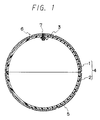
independent Claim 1. - Fig. 1 is a sectional view showing an embodiment of a ball according to the first invention of the present invention;
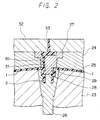
- Fig. 2 is a sectional view showing an embodiment of a mold for the ball
- Figs. 3 through 8 are each a sectional view showing how the components of the mold in Fig. 2 move;
- Fig. 9 is a sectional view showing a base body of the ball;
- Fig. 10 is a plan view showing a valve portion of the base body in Fig. 9;
- Fig. 11 is a sectional view taken along X X line of Fig. 10 for showing a state where a valve rubber is removed from the valve of the base body; and
- Fig. 12 is a sectional view showing a conventional mold for ball.
- Referring to Fig. 1,
numeral hollow body 1 is integrally formed at the center thereof with avalve 3. The two hemisphericalhollow bodies base body 4. - The 10 % tensile stress of the thermoplastic elastomer forming the
base body 4 andvalve 3 needs to be set within the range of 30 to 190 kg/cm². If the value does not reach 30 kg/cm², the ball is expanded and deformed by the internal pressure and hence cannot maintain its designed size. On the contrary, the value exceeding 190 kg/cm² results in too small deformation upon impact and hence makes the touch of the ball hard. Therefore, the player comes to feel a pain at the body, hand, leg or the like when hitted by such ball. In addition too large the value results in unsuitable bounce for controlling the ball; hence it is impossible to realize a ball suitable for games. If the 10 % tensile stress is within the above-mentioned range, the impact resilience (JIS K 6301) can be set within the range of 40 to 80 %, which range assures a suitable bounce for soccer, basket ball, volley ball and the like. - The thermoplastic elastomer having the above-mentioned characteristics can be selected, singly or in composition, from the following elastomers of appropriate grade:
thermoplastic polyurethane:
PARABLENE (trademark, a product of NIPPON POLY URETHANE CO., LTD.), TAKERAKKU (trademark, a product of TAKEDA-BADISCH URETHANE INDUSTRIES LTD.), TOYOBO URETHANE (a product of TOYOBO CO., LTD.), Desmopan (trademark, a product of BAYEL CO., LTD.), MIRACTRAN (trademark, a product of NIPPON MIRACTRAN CO., LTD.), ELASTOLLAN (trademark, a product of NIPPON ELASTOLLAN INDUSTRIES LTD.), Pandex (trademark, a product of DAINIPPON INK & CHEMICALS, INC.), MOBILON (trademark, a product of NISSHINBO INDUSTRIES, INC.).
polyester-series thermoplastic elastomer:
PELPRENE (trademark, a product of TOYOBO CO., LTD.), HYTREL (trademark, a product of DU PONT-TORAY CO., LTD.), GRILUX E (trademark; a product of DAINIPPON INK & CHEMICALS, INC.).
polyamide-series thermoplastic elastomer:
PEBAX (trademark, a product of TORAY INDUSTRIES INC.), GRILUX A (trademark, a product of DAINIPPON INK & CHEMICALS, INC).
polyolefine-series thermoplastic elastomer:
SUMITOMO TPE (a product of SUMITOMO CHEMICAL CO., LTD.), MILASTOMER (trademark, a product of MITSUI PETROCHEMICAL LTD.), SANTOPRENE (trademark, a product of AES JAPAN LTD.), TAFMER (trademark, a product of MITSUI PETROCHEMICAL LTD.).
styrene-series thermoplastic elastomer:
TUFPRENE (trademark, a product of ASAHI CHEMICAL INDUSTRIES CO., LTD.), KRATON (trademark, a product of SHELL JAPAN LTD.), JSR TR (JAPAN SYNTHETIC RUBBER CO., LTD.).
polyvinylchloride-series thermoplastic elastomer:
SUMIFLEX (trademark, a product of SUMITOMO BAKELITE CO., LTD.), SANPRENE (trademark, a product of MITSUBISHI KASEI VINYL CO.).
polybutadiene-series thermoplastic elastomer:
JSR RB (a product of JAPAN SYNTHETIC RUBBER CO., LTD.),
soft nylon
GRILUX N (trademark, a product of DAINIPPON INK & CHEMICALS, INC.). - In the case of forming a soccer ball, the
base body 4 is bonded, at the surface thereof, with leather orsynthetic leather panels panels adjacent panels Numeral 7 denotes a valve rubber as a component of thevalve 3, which is removably mounted into thevalve 3 and inserted with a needle of air injector to permit compressed air to be injected into thebase body 4. - A base body of a soccer ball of
size 5 was formed to 1.3 mm thick using as the thermoplastic elastomer material a polyester-series elastomer, or specifically PELPRENE (trademark, a product of TOYOBO CO., LTD.). The base body was then bonded with leather panels and injected with compressed air to an internal pressure of 0.6 kg/cm², which valve was as same as that for a common soccer ball. The 10 % tensile stress and impact resilience of the resulting ball were 74 kg/cm² and 50.4 %, respectively and suitable for a soccer ball. The impact or shock caused when the ball hitted a player was almost the same as that caused by a conventional ball of a thread wound structure; accordingly, the player felt little pain. In addition, deformation of the ball when kicked was appropriate, and the touch thereof was preferable. Deformation due to expansion did not occur after the ball was allowed to stand for 6 months with its internal pressure maintained. Thus, it was confirmed that the ball was excellent in shape-maintaining property without expansion. - Described next is a mold for forming the
base body 4 of the ball. - Referring to Figs. 9 to 11,
numerals hollow bodies base body 4. Avalve 3 is formed integrally with the hemisphericalhollow body 1, inwardly projected at the center of thebody 1, and has a valverubber insertion hole 14. The valverubber insertion hole 14 comprises an outside and small-diameter portion 15 situated on the surface-side of the ball and having a diameter of about 6 to 8 mm and a length of about 3 to 5 mm, an intermediate and large-diameter portion 16 having a diameter of about 9.5 to 11.5 mm and a length of about 3 to 4.5 mm, and an inside and small-diameter portion 17 having a diameter of about 5 to 6 mm and a length of about 9 to 10 mm. Aslit 18 is provided in the outside and small-diameter portion 15 for facilitating withdrawal of a second valve mold 27 (shown in Fig. 2). Avalve rubber 7 is shaped as substantially the same as or slighty larger than the contour of the valverubber insertion hole 14. Denoted bynumeral 20 is a small aperture formed centrally of thevalve rubber 7, for insertion of a needle of air injector, and bynumeral 21 is a cut. In Fig. 10, denoted bynumerals - Referring to Fig. 2, denoted by
numeral 23 is a first mold having a hemispherical convex, and by numeral 24 a second mold having a hemispherical concave larger in size than the hemispherical convex of thefirst mold 23, whichmolds cavity 25 for forming the hemispherical hollow body. In forming thebase body 4 of a soccer ball ofsize 5, thecavity 25 is set to have a diameter of 21.5 cm at the peripheral end thereof and a thickness of 1.0 mm.Numeral 26 denotes a first valve mold disposed centrally of the surface of hemispherical convex of thefirst mold 23 and removable in the direction toward the center the hemisphere, which valve mold is for forming the outer form of thevalve 3 and the inside and small-diameter portion 17 of the valverubber insertion hole 14.Numeral 27 denotes a second valve mold disposed contrally of the surface of hemispherical concave of thesecond mold 24 and removable in the direction outwardly from thesecond mold 24, i.e., in the direction toward the side opposite to thefirst mold 23, which valve mold is for forming the intermediate and large-diameter portion 16 and outside and small-diameter portion 15 of the valverubber insertion hole 14. Acavity 28 for forming thevalve 3 is defined between the first andsecond valve molds plate projections 29 are provided in the outside and small-diameter portion 15 associated with thesecond valve mold 27, for forming theslit 18. Threerunners 30 are formed in thesecond valve mold 27 for injecting heat-plasticized or molten thermoplastic elastomer into thecavity 25 throughgates 31 disposed in the periphery of the outside and small-diameter portion 15 of the valverubber insertion hole 14.Numeral 32 denotes a sprue mold disposed outside thesecond mold 24 andsecond valve mold 27, for providing asprue 33 to be contacted with a nozzle of a resin-injector (not shown), through whichsprue 33 resin or thermoplastic elastomer is supplied to therunners 30. - With reference to Figs. 3 to 8, steps of releasing the hemispherical
hollow body 1 thus molded from the molds are sequentially described. - Firstly, the
first mold 23 is moved in the direction indicated by arrow a, to be released from thefirst valve mold 26 and the hemispherical hollow body 1 (see Fig. 3). Subsequently, thefirst valve mold 26 is moved in the direction indicated by arrow b, to be released from the hemispherical hollow body 1 (see Fig. 4). Simultaneously with or subsequent to the movement of thefirst valve mold 26, thesprue mold 32 is moved outwardly or in the direction indicated by arrow c, to be released from thesecond mold 24. At this moment, the resin in the tip end portion of therunner 30 is cut at thegate 31, and the resin in thesprue 33 and in therunner 30 is moved upwardly in the drawing, together with the sprue mold 32 (see Fig. 5). Thereafter, thesecond valve mold 27 is made to move in the direction indicated by arrow d in Fig. 6, to be released from thesecond mold 24. At this time, although a diametrically-enlarged portion 34 at the lower end of thesecond valve mold 27 is caught by the resin in the outside and small-diameter portion 15, the presence of the resin in theslit 18 enables it to be withdrawn therefrom without causing any damage. Since the inside and small-diameter portion 17 has been already released or withdrawn, the resin in theportion 17 becomes prone to deform inwardly, or in the direction toward the axis thereof. Accordingly, the resin in the outside and small-diameter portion 15 is easy to enlarge and the release of thesecond valve mold 27 can further be facilitated. Thus, thesecond valve mold 27 is released from the hemispherical hollow body 1 (see Fig. 7). Next, thesecond valve mold 27 is moved downwardly as indicated by arrow e, to be fitted again into the second mold 24 (see Fig. 8). This causes the hemisphericalhollow body 1 to be pressed down with the lower end of thesecond valve mold 27. As a result, the hemisphericalhollow body 1 stuck to thesecond mold 24 can be released therefrom. Thus, the hemisphericalhollow body 1 can be released from the molds by only moving the molds in a completely automatic fashion. - The hemispherical
hollow body 1 integrated with the above-mentionedvalve 3 is completed having an outer circumference of about 67 cm at the end thereof, and a thickness of about 0.5 to 2.5 mm. This hemisphericalhollow body 1 is bonded with the counterpart hemisphericalhollow body 2 not having a valve, at the peripheral ends thereof by heat-fusion to form abase body 4. Specifically, the peripheral end portions of these two hemisphericalhollow bodies hollow base body 4. The heating of the peripheral end portions of the two hemisphericalhollow bodies bodies hollow bodies bodies hollow bodies base body 4 thus formed is bonded, at its surface, with twenty hexagonal leather panel and twelve pentagonal leather panel. Thus, a soccer ball of the invention is completed. - According to the first invention of the present invention, two hemispherical hollow bodies are molded from a thermoplastic elastomer material, and bonded together to form a base body of a ball, while setting the 10 % tensile stress of this material within the range of 30 to 190 kg/cm², thereby meeting the requirements for a ball such as shock-absorptivity impact resilience, shape-maintaining property and the like.
Claims (1)
- A ball for ball games, such as a soccer ball, a volley ball, comprising a base body (4) composed of two hemispherical hollow bodies (1, 2) formed by injection-molding a thermoplastic elastomer and bonded together to form a spherical hollow body, said base body (4) containing and sealing compressed air injected therein through an air-injection valve (3) provided at an appropriate portion of one (1) of said two hemispherical hollow bodies, and a plurality of leather panels (5) bonded by means of an adhesive to the surface of said body (4), whereas the side edges of each of said leather panels (5) being obliquely cut to form grooves (6) drawing boundaries with adjacent panels (5), wherein a 10 % tensile stress of said thermoplastic elastomer forming said base body (4) ranges from 30 to 190 kg/cm².
Priority Applications (6)
| Application Number | Priority Date | Filing Date | Title |
|---|---|---|---|
| ES92117713T ES2091379T3 (en) | 1992-10-16 | 1992-10-16 | BALL FOR GAME OF BALL. |
| US07/962,331 US5306001A (en) | 1992-10-16 | 1992-10-16 | Game ball |
| DE1992611554 DE69211554T2 (en) | 1992-10-16 | 1992-10-16 | Ball for a ball game |
| EP95111104A EP0703053A1 (en) | 1992-10-16 | 1992-10-16 | Mold for forming a ball for ball game |
| EP92117713A EP0592719B1 (en) | 1992-10-16 | 1992-10-16 | Ball for ball game |
| US08/095,419 US5380185A (en) | 1992-10-16 | 1993-07-22 | Ball for ball game and molding apparatus for forming the same |
Applications Claiming Priority (3)
| Application Number | Priority Date | Filing Date | Title |
|---|---|---|---|
| US07/962,331 US5306001A (en) | 1992-10-16 | 1992-10-16 | Game ball |
| EP92117713A EP0592719B1 (en) | 1992-10-16 | 1992-10-16 | Ball for ball game |
| US08/095,419 US5380185A (en) | 1992-10-16 | 1993-07-22 | Ball for ball game and molding apparatus for forming the same |
Related Child Applications (1)
| Application Number | Title | Priority Date | Filing Date |
|---|---|---|---|
| EP95111104.6 Division-Into | 1992-10-16 |
Publications (2)
| Publication Number | Publication Date |
|---|---|
| EP0592719A1 EP0592719A1 (en) | 1994-04-20 |
| EP0592719B1 true EP0592719B1 (en) | 1996-06-12 |
Family
ID=27234545
Family Applications (1)
| Application Number | Title | Priority Date | Filing Date |
|---|---|---|---|
| EP92117713A Expired - Lifetime EP0592719B1 (en) | 1992-10-16 | 1992-10-16 | Ball for ball game |
Country Status (2)
| Country | Link |
|---|---|
| US (2) | US5306001A (en) |
| EP (1) | EP0592719B1 (en) |
Families Citing this family (23)
| Publication number | Priority date | Publication date | Assignee | Title |
|---|---|---|---|---|
| DE19624020C1 (en) * | 1996-02-12 | 1997-05-07 | Ulrich Plaetke | Sports ball with rubber elastic bladder |
| US6048283A (en) * | 1997-06-24 | 2000-04-11 | Amloid Corporation | Toy game implements |
| US5766104A (en) * | 1997-06-24 | 1998-06-16 | Amloid Corporation | Toy striking implements |
| US6422961B1 (en) * | 1999-01-25 | 2002-07-23 | Spalding Sports Worldwide, Inc. | Rubber basketball with skived channel look |
| US6403003B1 (en) | 1999-08-10 | 2002-06-11 | Jetta Company Limited | Injection molded doll head |
| US6517471B2 (en) * | 2001-06-11 | 2003-02-11 | Szu-Jen Chen | Exercise ball with an air layer |
| HRPK20020052B3 (en) * | 2002-01-21 | 2005-04-30 | Zvjezdan Palenkić Filip Katinić | Making of module ball |
| US20030211919A1 (en) * | 2002-05-09 | 2003-11-13 | Sung-Yeng Chen | Physical exercising ball and its fabrication method |
| US7175413B1 (en) | 2002-09-23 | 2007-02-13 | Owens-Illinois Closure Inc. | Elastomeric dispensing valve manufacture |
| US20080064540A1 (en) * | 2006-09-08 | 2008-03-13 | Ching Wan Chen | Game ball |
| US20120329587A1 (en) * | 2006-12-11 | 2012-12-27 | Tsung Ming Ou | Sports ball |
| GB2456329B (en) * | 2008-01-11 | 2012-02-15 | Sean William Mumbray | A plaything |
| US8182379B2 (en) | 2008-06-27 | 2012-05-22 | Nike, Inc. | Sport balls and methods of manufacturing the sport balls |
| US8708847B2 (en) | 2008-06-27 | 2014-04-29 | Nike, Inc. | Sport ball casing and methods of manufacturing the casing |
| US8852039B2 (en) | 2011-06-28 | 2014-10-07 | Nike, Inc. | Sport ball casing with integrated bladder material |
| DE102009022252B4 (en) * | 2009-05-20 | 2014-12-18 | Puma SE | Method of making a ball and ball |
| US8672784B2 (en) | 2011-05-04 | 2014-03-18 | Nike, Inc. | Sport ball with an inflation-retention bladder |
| US8771115B2 (en) | 2011-05-04 | 2014-07-08 | Nike, Inc. | Sport ball with an inflation-retention bladder |
| CN102218835A (en) * | 2011-06-02 | 2011-10-19 | 罗传兴 | Liner of ball sports product and manufacture method thereof as well as ball sports product |
| KR20160111367A (en) * | 2013-12-27 | 2016-09-26 | 가부시키가이샤 모루텐 | Ball |
| DE102015209811B3 (en) * | 2015-05-28 | 2016-12-01 | Adidas Ag | Non-inflatable sports balls |
| US10286259B2 (en) | 2015-08-31 | 2019-05-14 | Mark Hartelius | Play ball with foam filling |
| US10653923B2 (en) * | 2017-10-24 | 2020-05-19 | Tsung Ming Ou | Channelless basketball and manufacturing method thereof |
Family Cites Families (14)
| Publication number | Priority date | Publication date | Assignee | Title |
|---|---|---|---|---|
| US3849053A (en) * | 1971-02-10 | 1974-11-19 | Sterigard Corp | Mold for fabricating the housing of a dispensing valve for pressurized dispensers |
| JPS5239328B2 (en) * | 1972-06-05 | 1977-10-04 | ||
| US3933967A (en) * | 1973-02-20 | 1976-01-20 | Taylor Don A | Method of making seamless hollow molded articles |
| US3837612A (en) * | 1973-06-01 | 1974-09-24 | Red Jacket Mfg Co | Mold apparatus for mixed flow impeller |
| FR2324325A1 (en) * | 1975-10-30 | 1977-04-15 | Piraud Jean Daniel | SPORTS BALL |
| US4340222A (en) * | 1980-06-30 | 1982-07-20 | Wham-O Mfg. Co. | Game ball |
| JPS60225581A (en) * | 1984-04-23 | 1985-11-09 | 株式会社 モルテン | Ball for ball game and its production |
| US4649234A (en) * | 1984-07-26 | 1987-03-10 | Siemens Aktiengesellschaft | Circuit arrangement for telecommunications exchange systems, particularly telephone exchange systems, comprising information processing sequential logic systems and traffic measuring devices |
| US4660831A (en) * | 1985-09-16 | 1987-04-28 | Figgie International Inc. | Inflatable padded game ball |
| US4765853A (en) * | 1987-10-07 | 1988-08-23 | Hoffman Allan C | Method of making a pressurized ball |
| JPH0388567A (en) * | 1989-08-31 | 1991-04-12 | Canon Inc | Image forming device |
| KR940006682Y1 (en) * | 1990-06-26 | 1994-09-28 | 스폴딩 앤드 이본플로 캄파니 인코포레이티드 | Golf ball injection mold |
| US5135700A (en) * | 1990-11-06 | 1992-08-04 | Nibco Inc. | Method and apparatus for molding a threaded product |
| US5156864A (en) * | 1991-02-06 | 1992-10-20 | Guo Muh Juh | Plastics threaded fitting molding mechanism |
-
1992
- 1992-10-16 EP EP92117713A patent/EP0592719B1/en not_active Expired - Lifetime
- 1992-10-16 US US07/962,331 patent/US5306001A/en not_active Expired - Fee Related
-
1993
- 1993-07-22 US US08/095,419 patent/US5380185A/en not_active Expired - Fee Related
Also Published As
| Publication number | Publication date |
|---|---|
| US5380185A (en) | 1995-01-10 |
| US5306001A (en) | 1994-04-26 |
| EP0592719A1 (en) | 1994-04-20 |
Similar Documents
| Publication | Publication Date | Title |
|---|---|---|
| EP0592719B1 (en) | Ball for ball game | |
| US7470203B1 (en) | Enhanced-grip play balls and methods of manufacture | |
| US6729984B2 (en) | Toy ball apparatus | |
| US5836834A (en) | Golf balls | |
| US4340222A (en) | Game ball | |
| US6012992A (en) | Golf ball having a cover with variable characteristics | |
| US6056622A (en) | Balls with unpredictable bounce | |
| US6403003B1 (en) | Injection molded doll head | |
| JPH1189970A (en) | Golf ball | |
| JP2002540865A (en) | Method of manufacturing multilayer core golf ball | |
| JPH1176466A (en) | Golf ball injection molding die and golf ball | |
| US5033498A (en) | Valve for inflated article | |
| JP3477509B2 (en) | Golf ball manufacturing method | |
| JP2543676Y2 (en) | Mold for molding ball base for ball games | |
| EP0703053A1 (en) | Mold for forming a ball for ball game | |
| JP2007301267A (en) | Golf tee | |
| US20040082413A1 (en) | Pressurized sports hitting implement | |
| JP2000237351A (en) | Production of golf ball | |
| JP2001286589A (en) | Golf tee | |
| JP3967686B2 (en) | Golf tee | |
| KR100651925B1 (en) | Menufacturing method of finger ball and mold used in such method | |
| JP3536040B2 (en) | Manufacturing method of rod-shaped molded body | |
| JP3009622U (en) | Golf practice balls | |
| WO2001062348A3 (en) | Game ball center having outer layer of injection molded ionomer | |
| JP3103331U (en) | Ball with inflatable body stored in outer skin |
Legal Events
| Date | Code | Title | Description |
|---|---|---|---|
| PUAI | Public reference made under article 153(3) epc to a published international application that has entered the european phase |
Free format text: ORIGINAL CODE: 0009012 |
|
| AK | Designated contracting states |
Kind code of ref document: A1 Designated state(s): DE ES FR GB IT |
|
| 17P | Request for examination filed |
Effective date: 19940707 |
|
| 17Q | First examination report despatched |
Effective date: 19950316 |
|
| GRAH | Despatch of communication of intention to grant a patent |
Free format text: ORIGINAL CODE: EPIDOS IGRA |
|
| GRAA | (expected) grant |
Free format text: ORIGINAL CODE: 0009210 |
|
| XX | Miscellaneous (additional remarks) | ||
| AK | Designated contracting states |
Kind code of ref document: B1 Designated state(s): DE ES FR GB IT |
|
| REF | Corresponds to: |
Ref document number: 69211554 Country of ref document: DE Date of ref document: 19960718 |
|
| ITF | It: translation for a ep patent filed |
Owner name: MODIANO & ASSOCIATI S.R.L. |
|
| PGFP | Annual fee paid to national office [announced via postgrant information from national office to epo] |
Ref country code: GB Payment date: 19961007 Year of fee payment: 5 |
|
| ET | Fr: translation filed | ||
| PGFP | Annual fee paid to national office [announced via postgrant information from national office to epo] |
Ref country code: ES Payment date: 19961015 Year of fee payment: 5 |
|
| PGFP | Annual fee paid to national office [announced via postgrant information from national office to epo] |
Ref country code: FR Payment date: 19961016 Year of fee payment: 5 |
|
| REG | Reference to a national code |
Ref country code: ES Ref legal event code: FG2A Ref document number: 2091379 Country of ref document: ES Kind code of ref document: T3 |
|
| PGFP | Annual fee paid to national office [announced via postgrant information from national office to epo] |
Ref country code: DE Payment date: 19961221 Year of fee payment: 5 |
|
| PLBE | No opposition filed within time limit |
Free format text: ORIGINAL CODE: 0009261 |
|
| STAA | Information on the status of an ep patent application or granted ep patent |
Free format text: STATUS: NO OPPOSITION FILED WITHIN TIME LIMIT |
|
| 26N | No opposition filed | ||
| PG25 | Lapsed in a contracting state [announced via postgrant information from national office to epo] |
Ref country code: GB Free format text: LAPSE BECAUSE OF NON-PAYMENT OF DUE FEES Effective date: 19971016 |
|
| PG25 | Lapsed in a contracting state [announced via postgrant information from national office to epo] |
Ref country code: ES Free format text: LAPSE BECAUSE OF NON-PAYMENT OF DUE FEES Effective date: 19971017 |
|
| PG25 | Lapsed in a contracting state [announced via postgrant information from national office to epo] |
Ref country code: FR Free format text: THE PATENT HAS BEEN ANNULLED BY A DECISION OF A NATIONAL AUTHORITY Effective date: 19971031 |
|
| GBPC | Gb: european patent ceased through non-payment of renewal fee |
Effective date: 19971016 |
|
| PG25 | Lapsed in a contracting state [announced via postgrant information from national office to epo] |
Ref country code: DE Free format text: LAPSE BECAUSE OF NON-PAYMENT OF DUE FEES Effective date: 19980701 |
|
| REG | Reference to a national code |
Ref country code: FR Ref legal event code: ST |
|
| REG | Reference to a national code |
Ref country code: ES Ref legal event code: FD2A Effective date: 19981113 |
|
| PG25 | Lapsed in a contracting state [announced via postgrant information from national office to epo] |
Ref country code: IT Free format text: LAPSE BECAUSE OF NON-PAYMENT OF DUE FEES;WARNING: LAPSES OF ITALIAN PATENTS WITH EFFECTIVE DATE BEFORE 2007 MAY HAVE OCCURRED AT ANY TIME BEFORE 2007. THE CORRECT EFFECTIVE DATE MAY BE DIFFERENT FROM THE ONE RECORDED. Effective date: 20051016 |