EP0592596B1 - Cover slip holder for bilateral and unilateral simulation of thrombogenesis in partly occluded blood vessels - Google Patents
Cover slip holder for bilateral and unilateral simulation of thrombogenesis in partly occluded blood vessels Download PDFInfo
- Publication number
- EP0592596B1 EP0592596B1 EP92915623A EP92915623A EP0592596B1 EP 0592596 B1 EP0592596 B1 EP 0592596B1 EP 92915623 A EP92915623 A EP 92915623A EP 92915623 A EP92915623 A EP 92915623A EP 0592596 B1 EP0592596 B1 EP 0592596B1
- Authority
- EP
- European Patent Office
- Prior art keywords
- cover slip
- chamber
- slip holder
- cover
- cross
- Prior art date
- Legal status (The legal status is an assumption and is not a legal conclusion. Google has not performed a legal analysis and makes no representation as to the accuracy of the status listed.)
- Expired - Lifetime
Links
- 210000004204 blood vessel Anatomy 0.000 title abstract description 9
- 238000004088 simulation Methods 0.000 title abstract description 6
- 230000002146 bilateral effect Effects 0.000 title abstract description 4
- 230000010412 perfusion Effects 0.000 claims abstract description 69
- 239000000463 material Substances 0.000 claims description 17
- 229920003023 plastic Polymers 0.000 claims description 10
- 239000012620 biological material Substances 0.000 claims description 8
- 239000000126 substance Substances 0.000 claims description 5
- 150000001875 compounds Chemical class 0.000 claims description 3
- 230000007704 transition Effects 0.000 claims description 3
- 238000003780 insertion Methods 0.000 claims description 2
- 230000037431 insertion Effects 0.000 claims description 2
- 238000007789 sealing Methods 0.000 claims description 2
- 230000017531 blood circulation Effects 0.000 abstract description 35
- 208000031481 Pathologic Constriction Diseases 0.000 abstract description 8
- 230000036262 stenosis Effects 0.000 abstract description 8
- 208000037804 stenosis Diseases 0.000 abstract description 8
- 238000011144 upstream manufacturing Methods 0.000 abstract description 6
- 239000008280 blood Substances 0.000 description 20
- 210000004369 blood Anatomy 0.000 description 20
- 239000000243 solution Substances 0.000 description 13
- 208000007536 Thrombosis Diseases 0.000 description 9
- 238000012360 testing method Methods 0.000 description 9
- 238000001727 in vivo Methods 0.000 description 8
- 210000002889 endothelial cell Anatomy 0.000 description 7
- 238000000034 method Methods 0.000 description 6
- 210000003462 vein Anatomy 0.000 description 6
- 239000000203 mixture Substances 0.000 description 5
- 230000001732 thrombotic effect Effects 0.000 description 5
- 102000008186 Collagen Human genes 0.000 description 4
- 108010035532 Collagen Proteins 0.000 description 4
- 230000015271 coagulation Effects 0.000 description 4
- 238000005345 coagulation Methods 0.000 description 4
- 229920001436 collagen Polymers 0.000 description 4
- 230000000694 effects Effects 0.000 description 4
- 239000011521 glass Substances 0.000 description 4
- 230000008569 process Effects 0.000 description 4
- 239000003805 procoagulant Substances 0.000 description 4
- 230000015572 biosynthetic process Effects 0.000 description 3
- 210000002808 connective tissue Anatomy 0.000 description 3
- 239000003814 drug Substances 0.000 description 3
- 239000002504 physiological saline solution Substances 0.000 description 3
- 206010003210 Arteriosclerosis Diseases 0.000 description 2
- 230000003213 activating effect Effects 0.000 description 2
- 230000008081 blood perfusion Effects 0.000 description 2
- 239000007853 buffer solution Substances 0.000 description 2
- 238000011161 development Methods 0.000 description 2
- 230000003028 elevating effect Effects 0.000 description 2
- 238000000338 in vitro Methods 0.000 description 2
- 238000001802 infusion Methods 0.000 description 2
- 238000005086 pumping Methods 0.000 description 2
- 229920002994 synthetic fiber Polymers 0.000 description 2
- 230000002885 thrombogenetic effect Effects 0.000 description 2
- 206010060965 Arterial stenosis Diseases 0.000 description 1
- 102000015081 Blood Coagulation Factors Human genes 0.000 description 1
- 108010039209 Blood Coagulation Factors Proteins 0.000 description 1
- 102000004127 Cytokines Human genes 0.000 description 1
- 108090000695 Cytokines Proteins 0.000 description 1
- SXRSQZLOMIGNAQ-UHFFFAOYSA-N Glutaraldehyde Chemical compound O=CCCCC=O SXRSQZLOMIGNAQ-UHFFFAOYSA-N 0.000 description 1
- 229920002319 Poly(methyl acrylate) Polymers 0.000 description 1
- 108020004511 Recombinant DNA Proteins 0.000 description 1
- 230000009471 action Effects 0.000 description 1
- 230000004913 activation Effects 0.000 description 1
- 230000002776 aggregation Effects 0.000 description 1
- 238000004220 aggregation Methods 0.000 description 1
- 108010027597 alpha-chymotrypsin Proteins 0.000 description 1
- 230000002785 anti-thrombosis Effects 0.000 description 1
- 230000010100 anticoagulation Effects 0.000 description 1
- 229960004676 antithrombotic agent Drugs 0.000 description 1
- 208000011775 arteriosclerosis disease Diseases 0.000 description 1
- 230000009286 beneficial effect Effects 0.000 description 1
- 239000003114 blood coagulation factor Substances 0.000 description 1
- 210000004027 cell Anatomy 0.000 description 1
- 239000011248 coating agent Substances 0.000 description 1
- 238000000576 coating method Methods 0.000 description 1
- 210000004351 coronary vessel Anatomy 0.000 description 1
- 230000008021 deposition Effects 0.000 description 1
- 238000005516 engineering process Methods 0.000 description 1
- 238000002474 experimental method Methods 0.000 description 1
- 238000010191 image analysis Methods 0.000 description 1
- 230000002401 inhibitory effect Effects 0.000 description 1
- 239000007924 injection Substances 0.000 description 1
- 238000002347 injection Methods 0.000 description 1
- 230000003902 lesion Effects 0.000 description 1
- 238000004619 light microscopy Methods 0.000 description 1
- 230000031915 positive regulation of coagulation Effects 0.000 description 1
- 230000001737 promoting effect Effects 0.000 description 1
- 230000009467 reduction Effects 0.000 description 1
- 238000011160 research Methods 0.000 description 1
- 238000000926 separation method Methods 0.000 description 1
- 239000007787 solid Substances 0.000 description 1
Images


Classifications
-
- G—PHYSICS
- G01—MEASURING; TESTING
- G01N—INVESTIGATING OR ANALYSING MATERIALS BY DETERMINING THEIR CHEMICAL OR PHYSICAL PROPERTIES
- G01N11/00—Investigating flow properties of materials, e.g. viscosity, plasticity; Analysing materials by determining flow properties
- G01N11/02—Investigating flow properties of materials, e.g. viscosity, plasticity; Analysing materials by determining flow properties by measuring flow of the material
- G01N11/04—Investigating flow properties of materials, e.g. viscosity, plasticity; Analysing materials by determining flow properties by measuring flow of the material through a restricted passage, e.g. tube, aperture
-
- B—PERFORMING OPERATIONS; TRANSPORTING
- B01—PHYSICAL OR CHEMICAL PROCESSES OR APPARATUS IN GENERAL
- B01F—MIXING, e.g. DISSOLVING, EMULSIFYING OR DISPERSING
- B01F25/00—Flow mixers; Mixers for falling materials, e.g. solid particles
- B01F25/30—Injector mixers
- B01F25/31—Injector mixers in conduits or tubes through which the main component flows
- B01F25/314—Injector mixers in conduits or tubes through which the main component flows wherein additional components are introduced at the circumference of the conduit
- B01F25/3141—Injector mixers in conduits or tubes through which the main component flows wherein additional components are introduced at the circumference of the conduit with additional mixing means other than injector mixers
-
- G—PHYSICS
- G01—MEASURING; TESTING
- G01N—INVESTIGATING OR ANALYSING MATERIALS BY DETERMINING THEIR CHEMICAL OR PHYSICAL PROPERTIES
- G01N33/00—Investigating or analysing materials by specific methods not covered by groups G01N1/00 - G01N31/00
- G01N33/48—Biological material, e.g. blood, urine; Haemocytometers
- G01N33/483—Physical analysis of biological material
- G01N33/487—Physical analysis of biological material of liquid biological material
- G01N33/49—Blood
- G01N33/4905—Determining clotting time of blood
-
- G—PHYSICS
- G09—EDUCATION; CRYPTOGRAPHY; DISPLAY; ADVERTISING; SEALS
- G09B—EDUCATIONAL OR DEMONSTRATION APPLIANCES; APPLIANCES FOR TEACHING, OR COMMUNICATING WITH, THE BLIND, DEAF OR MUTE; MODELS; PLANETARIA; GLOBES; MAPS; DIAGRAMS
- G09B23/00—Models for scientific, medical, or mathematical purposes, e.g. full-sized devices for demonstration purposes
- G09B23/28—Models for scientific, medical, or mathematical purposes, e.g. full-sized devices for demonstration purposes for medicine
- G09B23/285—Models for scientific, medical, or mathematical purposes, e.g. full-sized devices for demonstration purposes for medicine for injections, endoscopy, bronchoscopy, sigmoidscopy, insertion of contraceptive devices or enemas
-
- Y—GENERAL TAGGING OF NEW TECHNOLOGICAL DEVELOPMENTS; GENERAL TAGGING OF CROSS-SECTIONAL TECHNOLOGIES SPANNING OVER SEVERAL SECTIONS OF THE IPC; TECHNICAL SUBJECTS COVERED BY FORMER USPC CROSS-REFERENCE ART COLLECTIONS [XRACs] AND DIGESTS
- Y10—TECHNICAL SUBJECTS COVERED BY FORMER USPC
- Y10S—TECHNICAL SUBJECTS COVERED BY FORMER USPC CROSS-REFERENCE ART COLLECTIONS [XRACs] AND DIGESTS
- Y10S435/00—Chemistry: molecular biology and microbiology
- Y10S435/808—Optical sensing apparatus
Definitions
- the invention relates to a cover slip holder as described in the premable of claim 1, for simulation of in vivo blood flow conditions in occluded blood vessels.
- the invention also relates to the accompanying parallel-plate perfusion chamber including the cover slip holder.
- One preferred embodiment of the perfusion chamber is when it is connected to a mixing device for mixing in vitro added solutions to the blood flow before reaching the parallel-plate perfusion chamber.
- the cover slip holder according to the present invention is inserted in a parallel-plate perfusion chamber, so that the bottom of the knob creates the roof/floor of a measure chamber and in the bottom of the knob a varying number of glass slides or cover slips, made of plastic or glass or any other material, are attached in specially made grooves.
- cover slips can/cannot be covered with a biological/synthetic material, and the surface levels of the cover slips vary in relation to each other and to the roof/floor of the measure chamber, to produce a varying unilateral constriction of the cross-sectional area of the flow slit.
- Bilateral constriction of the flow cross-sectional area can, in a special embodiment, be obtained by elevating an area of the bottom of the measure chamber, facing the cover slips of the cover slip holder.
- Minimum 20 mm upstream of the blood flow inlet of the parallel-plate perfusion chamber, preferably a mixing device functioning according to the venturi-principle, can be installed in the flow channel.
- a device in which blood is exposed to materials facilitating thrombogenesis under conditions simulating blood flow in human blood vessels is beneficial both for research and industry in the medical field.
- a venous catheter which is connected, by plastic tubes, with a parallel-plate perfusion chamber, and a pump, located downstream to the parallel-plate perfusion chamber, is it possible to maintain ex vivo (i.e. anti-coagulation is not used) blood flow through a perfusion chamber.
- an annular perfusion chamber has previously been constructed, in which flowing blood was brought in close contact with human subendothelium, digested with ⁇ -chymotrypsin which produced a surface which was rich in collagenous fibrils (Baumgartner, H.
- Collagenous fibrils are shown to be active in promoting aggregation of platelets in flowing blood (Baumgartner, H. R., Thromb. Haemost. 37 : 1, 1977). More recently, perfusion chambers with rectangular cross-section of the blood flow slit have been constructed, in which a commercially available glass slide or plastic cover slip is attached in a specially made groove, located 90° on the flow direction. This glass slide or plastic cover slip, which surface is on the same level as that of the roof of the chamber, was covered by biological material (endothelial cells, connective tissue from endothelial cells and collagen) to promote thrombogenesis (Sakariassen, K.
- This perfusion chamber has a flow channel, in which the cross-section is changed from circular in the supply tubing to rectangular in the measure chamber and back to circular, usually accompanied by changed cross-sectional area. Such changes can lead to labile flow conditions or flow separation in the measure chamber.
- the perfusion chamber was therefore modified such that the transition from circular to rectangular dimensions of the flow channel was smooth. It was calculated that the reduction of the pressure gradient in this system, owing to the lesser kinetic energy, was less than 5% of the acting viscous force.
- the mentioned modified perfusion chamber makes possible an ex vivo test system for simulation of in vivo blood flow conditions by utilizing non-anticoagulated blood. Activation of platelets and coagulation proximal to the perfusion chamber is minimal and within normal range.
- the perfusion chamber has a well defined thrombogenic surface which triggers thrombus formation. Accordingly, the system is very well suited for testing effects of medicaments and compositions facilitating/inhibiting thrombogenetic processes.
- the mentioned perfusion chamber offers no possibility of testing the mentioned compositions under blood flow conditions simulating partly occluded blood vessels, which in vivo occur in atheromatosis and atheroschlerotic blood vessels and which is an important cause for thrombogenesis.
- adding solutions to a blood flow tube before the perfusion chamber will very often give incomplete mixing due to the laminar flow conditions.
- simulation of blood flow conditions in partly occluded blood vessels can be obtained in the present invention, by profilating the bottom of the cover slip holder with at least two different levels, such that local variation in the cross-sectional area in the measure chamber occurs.
- Cover slips with the surfaces coated with biological/synthetic material, can be attached to the bottom of the cover slip holder, which produces the constriction of the flow channel, and in addition immediate proximal and distal to the constriction.
- cover slips without coated surfaces, surfaces coated with biological materials activating coagulation (procoagulant surfaces), or coated with biological material not activating coagulation (non-procoagulant surfaces), or covered with native polymeric chemical compositions, in addition to the action of medicaments.
- cover slips proximal, on and distal to the constriction can be coated, or not coated, with a material which activates, or does not activate, coagulation, thus simulating in vivo vessel wall lesions.
- a mixing device is installed.
- This device secures homogenous mixing of the material added to the blood flow before it enters the perfusion chamber.
- the mixing device should be installed at a distance of at least 20 mm upstream to the perfusion chamber.
- the mixing device comprises a T-tube, in which the cross tube provides the main blood flow channel, and the addition of materials is performed through the side tube. The diameter of the flow channel is then constricted gradually and then suddenly expanded. This shape of the flow channel creates turbulent flow conditions which facilitate mixing of solutions added to the blood stream through the side tube, upstream to the constriction, and secures homogenous mixing of the added material in the blood.
- the parallel-plate perfusion chamber with the cover slip holder and possibly in connection with the mixing device are according to the invention characterized by the features as indicated in the claims.
- venous and arterial shear rates can be simulated in the perfusion chamber.
- Development of a stenosis in vivo can have an eccentric progress when it is developed from atheromatic conditions in the vessel wall. Simulation of such conditions can be obtained according to the present invention by an eccentric constriction of the flow channel by profilating, the bottom of the cover slip holder in the direction of the blood flow.
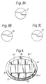
- the figures show a preferred embodiment of the cover slip holder according to the invention, with three cover slips and the location of the cover slip holder in the perfusion chamber.
- Fig. 1 shows the perfusion chamber 1 with a flow inlet connector 2 of standard type for connection to an arm vein via an infusion kit.
- a corresponding flow outlet connector 3 for connecting the perfusion chamber to a pump device.
- the flow channel 4 connects the inlet connector with the outlet connector and passes through a bored, elliptic well 5, in which the cover slip holder 6 according to the invention is inserted.
- Fig. 2 shows the cover slip holder 6 according to the invention in a section 90° (or perpendicular) to the flow direction (along the line I-I in Fig. 1), in which the bottom creates the roof of the measure chamber 7 when the cover slip holder is inserted in the perfusion chamber, and an O-ring 10 for sealing purposes. Insertion of the cover slip holder 6 in the perfusion chamber 1 (dotted draft) is shown.
- Fig. 2A shows a detail of a special embodiment of the invention, in which bilateral constriction of the flow channel is obtained by elevating the bottom of the measure chamber 20, facing the cover slips on the bottom of the cover slip holder.
- Fig. 3 shows the cover slip holder 6 according to the invention in a section along the flow channel (along the line II-II in Fig. 2) with grooves 11, 12, 13-1 adapted to commercially available plastic cover slips.
- Fig. 3A-3C show three examples of the sinusoidal wall of the elevation of the cover slip holder creating the constriction of the flow cross-sectional area in the measuring chamber.
- Fig. 4 shows the cover slip holder 6 according to the invention seen from above, with three cover slips 14, 15, 16-1 placed in the grooves 11, 12, 13-1 in the bottom of the cover slip holder.
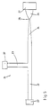
- Fig. 5 shows a mixing device 21 for homogenous mixing of solutions added to the blood flow.
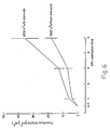
- Fig. 6 shows thrombus volume (»m3/»m2), as a function of perfusion time, in a measure chamber without elevation into the flow channel of the bottom of the cover slip holder (without stenosis) and in a measure chamber according to the invention with profilated bottom of the cover slip holder (with stenosis).
- Fig. 7 shows the percentage distribution of radioactivity in four parallel, equal sub-flows of the main flow (10 ml/min) of citrated blood after injecting or pumping (0,1-1 ml/min) a solution, containing 51CrO4 in physiological saline, through the side tube 23 in the mixing device (panel A).
- the sampled, equal sub-flows are connected downstream of the mixing device.
- the cover slip holder 6 is inserted in well 5 into the perfusion chamber 1 at a distance from the perfusion chamber inlet which is necessary to establish laminar blood flow conditions proximal to cover slip 14, positioned upstream to the constriction of the flow channel. This distance is at least 50 mm, preferably 70 mm.
- the parallel-plate perfusion chamber is constructed from a solid plastic material (for example polymethyl acrylate) and comprises two plates, placed adjacent to each other and secured by screws, as shown in Fig. 1.
- the elliptic well 5 is made as a hole in the upper plate. In the lower plate a groove is constructed, which, when the plates are placed adjacent to each other, creates the flow channel 4.
- the measure chamber 7 is defined as that part of the flow channel which is limited by the walls of the elliptic well 5.
- the bottom of the cover slip holder 6 is formed as a cross-located (compared to the flow direction), curved elevation which is fitted to a correspondingly curved depression, cut into the lower plate of the parallel-plate perfusion chamber.
- the dimensions of the flow channel (a, b) are selected by using formula I, in accordance with the shear rates and flow conditions which are necessary to obtain the wanted simulated conditions.
- the cover slip holder 6 is produced of the same material as the parallel-plate perfusion chamber and consists of a body, for examples formed as a cylinder with an elliptic cross-section 9 corresponding to the well 5 in the perfusion chamber (Fig. 2).
- a handle 8 can be made by increasing the cross-section of the body, with the same form as the elliptic cylinder 9, located such that the height of the cylinder 9 is equal to the thickness of the upper plate in the parallel-plate perfusion chamber.
- An O-ring 10 of suitable dimension is located around the cylinder 9 in order to prevent possible leakage of blood from the measure chamber.
- Cover slip grooves 11, 12, 13-1 are produced in the bottom of the cover slip holder, 90° on the flow direction.
- the debth of these grooves 11, 12, 13-1 equals the thickness of the cover slips and the distance between the grooves is 0,5 mm.
- the cover slips are attached in the grooves with a suitable attachment means.
- the cover slip grooves can also be permanently filled with a mass of any kind of material with the same thickness as the cover slips, in which case thrombus formation is initiated on a base which cannot be removed from the cover slip holder for examination.
- the proximal cover slip 14 in the roof of the measure chamber is on a level with the roof of the flow channel 4 in the perfusion chamber 1.
- the fundament of the groove 12 of the second cover slip 15 downstream is elevated, with straight or curved (for instance sinusoid) walls 17, 18, 19, in relation to the roof of the flow channel 4, in such a way that the cross-sectional area of the measure chamber is constricted in relation to the cross-sectional area of the flow channel.
- the level difference between the proximal (14) and middle (15) cover slip can vary in such a way that the cross-sectional area of the measure chamber at this place can be occluded up to 95% of the cross-sectional area of the flow channel 4.
- the grooves for the distal cover slips 16-1 to 16-4 can for instance be levelled with the proximal cover slip groove 11 or the level can be changed in relation to the first cover slip groove 11.
- the size of the cover slip holder 6 is adjusted according to the desired number of cover slips, which at least is 1 and is preferably between 1 and 6.
- Partial concentric occlusion of a blood vessel is simulated by elevation of the bottom 20 of the measure chamber 7 in the perfusion chamber 1 into the measure chamber 7, in such a way that the cross-sectional area of the flow channel is constricted bilaterally, both from the roof and bottom of the measure chamber.
- the surface of the cover slips can be uncoated or coated with biological material, or chemical compositions which it is desirable to test.
- biological materials which may be mentioned, are living cells, previously stimulated or non-stimulated.
- Non-procoagulant material may comprise collagenous fibrils, non-stimulated cultures of human endothelial cells and extracellular connective tissue deposited from the mentioned endothelial cells or components thereof.
- Procoagulant material may comprise human endothelial cells treated with, for instance endotoxine or cytokines, and connective tissue deposited by the treated endothelial cells or components thereof.
- the biological material may comprise compounds produced by recombinant DNA technology.
- Synthetic chemical compositions which modify, or do not modify, thrombotic processes will also represent possible coats or films on the exposed surfaces of the cover slips.
- all coats of biological material, recombinant material and synthetic compounds (medicaments), with our without effect on thrombotic processes are regarded to be within the idea and scope of the invention.
- the procedures for coating the cover slips are known from the literature.
- a typical perfusion experiment lasts for instance 5 min and requires 50 ml blood (10 ml/min) from the blood donor.
- the blood perfusion is directly followed by a 20 s perfusion (10 ml/min) with a physiological buffer solution which washes out the blood from the perfusion chamber, and then followed by a 40 s perfusion (10 ml/min) with a solution which fixes the thrombotic dseposits on the reactive surface in the perfusion chamber.
- the reactive surface with the fixed thrombotic material is subsequently removed from the perfusion chamber and embedded in plastic (Epon). 1 »m thin sections are produced from the cast material, stained and morphologically evaluated by the use of light-microscopy and a image analyzing system. The size of the thrombus on the reactive surface is expressed as volume of the thrombus per surface unit.
- the mixing device 21 is used, installed into the flow channel between the vein and the perfusion chamber 1.
- the mixing device 21 comprises a modified T-tube, as shown in Fig. 5, in which the side tube 23, equipped with a standard connector 27, allows pumping or injection of optional solutions into the blood flowing through the main tube 22, which is equipped with standard connectors 27 in both ends.
- the inner diameter of the main tube or blood flow tube 22 and side tube 23 can preferably be 2,0 mm, or be adapted to the existing experimental conditions.
- the blood flow tube is gradually constricted over a suitable distance 24, for example 12 mm, to a point 25 with for example inner diameter of 0,5 mm, thereafter the tube is expanded over a considerably shorter distance 26, for examples 5 mm, to a diameter considerably larger than the diameter of the blood flow tube 22, for example 4,0 mm.
- a suitable distance downstream of the side tube 23 for example 12 mm
- the tube is expanded over a considerably shorter distance 26, for examples 5 mm, to a diameter considerably larger than the diameter of the blood flow tube 22, for example 4,0 mm.
- the mixing device 21 is located at least 20 mm upstream of the inlet connector 2 in the perfusion chamber 1.
- Non-anticoagulated human blood was drawn directly from an anticubital vein over three cover slips.
- Purified human collagen was coated on cover slip 15 and endothelial cells on cover slips 14 and 16-1 on the cover slip holder 6 in the measure chamber 7.
- the anticubital vein was punctured by a "butterfly" infusion needle and the blood was drawn through the blood flow channel 4 to the measure chamber 7 by a pump, placed distally to the perfusion chamber.
- the blood flow was 10 ml/min and the perfusion lasted from 1 to 15 min.
- the thrombi on the cover slip with collagen at the constriction of the flow channel in the measure chamber partly occluded the blood flow through the chamber after 3 min, when the occlusion initially constricted the blood flow channel with >80%. Occlusion of the blood flow channel ⁇ 60% produced smaller thrombi. All the occluded chambers produced significant thrombogenesis within 1 min.
- the perfusion chamber was perfused for 20 s with a physiological buffer solution immediately after the blood perfusion, followed by a perfusion for 40 sec with a glutaraldehyde solution to fix the thrombus. All perfusions were performed with continous flow through the chamber, by means of T-tubes, without stopping the pump.
- This example relates to a comparison of thrombogenesis in a measure chamber without profiled bottom of the cover slip holder with that of a measure chamber according to the invention, in which the bottom of the cover slip holder is elevated to simulate arterial stenosis with shear rates equal to 2600 s ⁇ 1.
- Non-anticoagulated blood from an anticubital vein was pumped through the perfusion chamber with the cover slip holder according to the invention, with a flow rate of 10 ml/min, as described in Example 1.
- the elevation of the bottom in the cover slip holder occluded 50% of the cross-sectional area of the flow channel and created an unilateral stenosis.
- a cover slip on the constriction was coated with purified human collagen.
- the shear rate at the surface of this cover slip was 2600 s ⁇ 1. This equals a shear rate which can be observed in a coronary artery of average size with a 50% occluding stenosis.
- the measure chamber without a cover slip holder with elevated bottom was dimensioned so as to create shear rates of 2600 s ⁇ 1 in the measure chamber.
- the volume of the thrombus measured with an image analysis technique, was already after 3 min's perfusion significantly larger in the occluded measure chamber according to the invention and doubled after 5 min, compared to the thrombus volume in the measure chamber without occlusion.
- This demonstrates the impact of an initial occlusion in the measure chamber in order to simulate the development of thrombogenesis in in vivo vessel systems with stenosis.
- the test equipment comprised the mixing device 21 (Fig. 5) connected to a 20 mm tubing of the same dimension, which was connected to four equally long, parallel tubes with equal flow cross-sectional areas (1/4 of the flow cross-sectional area of the main flow).
- This assembly caused a blood flow through the mixing device to separate into four equivalent flows.
- Citrated blood was pumped through the mixing device (10 ml/min) as described in Example 1, while a solution of physiological saline containing 51CrO4 was continuously added (0,1-1 ml/min) through the side tube 23. The four sub-flows were collected and the radioactivity measured.
- Fig. 7 shows no significant difference in the percentage radioactivity (% of the injected radioactivity in the side tube) in the four sub-flows, in the test in which the mixing device 21 was used (A).
- A % of the injected radioactivity in the side tube
- B considerable differences in percent radioactivity collected from the four sub-flows appeared (B). This demonstrates that the mixing device produces a homogenous mixing of the radioactivity in the blood stream. This did not happen in the absence of the mixing device.
Landscapes
- Health & Medical Sciences (AREA)
- Engineering & Computer Science (AREA)
- Life Sciences & Earth Sciences (AREA)
- Physics & Mathematics (AREA)
- Chemical & Material Sciences (AREA)
- General Physics & Mathematics (AREA)
- Biomedical Technology (AREA)
- General Health & Medical Sciences (AREA)
- Biochemistry (AREA)
- Analytical Chemistry (AREA)
- Hematology (AREA)
- Medicinal Chemistry (AREA)
- Pathology (AREA)
- Immunology (AREA)
- Pulmonology (AREA)
- Molecular Biology (AREA)
- Business, Economics & Management (AREA)
- Educational Administration (AREA)
- Educational Technology (AREA)
- Theoretical Computer Science (AREA)
- Medical Informatics (AREA)
- Mathematical Physics (AREA)
- Radiology & Medical Imaging (AREA)
- Mathematical Optimization (AREA)
- Mathematical Analysis (AREA)
- Ecology (AREA)
- Computational Mathematics (AREA)
- Algebra (AREA)
- Biophysics (AREA)
- Pure & Applied Mathematics (AREA)
- Urology & Nephrology (AREA)
- Food Science & Technology (AREA)
- Chemical Kinetics & Catalysis (AREA)
- Investigating Or Analysing Biological Materials (AREA)
- External Artificial Organs (AREA)
- Infusion, Injection, And Reservoir Apparatuses (AREA)
- Sampling And Sample Adjustment (AREA)
- Agricultural Chemicals And Associated Chemicals (AREA)
- Medical Preparation Storing Or Oral Administration Devices (AREA)
- Dairy Products (AREA)
Abstract
Description
- The invention relates to a cover slip holder as described in the premable of
claim 1, for simulation of in vivo blood flow conditions in occluded blood vessels. The invention also relates to the accompanying parallel-plate perfusion chamber including the cover slip holder. One preferred embodiment of the perfusion chamber is when it is connected to a mixing device for mixing in vitro added solutions to the blood flow before reaching the parallel-plate perfusion chamber. - The cover slip holder according to the present invention is inserted in a parallel-plate perfusion chamber, so that the bottom of the knob creates the roof/floor of a measure chamber and in the bottom of the knob a varying number of glass slides or cover slips, made of plastic or glass or any other material, are attached in specially made grooves. These cover slips can/cannot be covered with a biological/synthetic material, and the surface levels of the cover slips vary in relation to each other and to the roof/floor of the measure chamber, to produce a varying unilateral constriction of the cross-sectional area of the flow slit. Bilateral constriction of the flow cross-sectional area can, in a special embodiment, be obtained by elevating an area of the bottom of the measure chamber, facing the cover slips of the cover slip holder. Minimum 20 mm upstream of the blood flow inlet of the parallel-plate perfusion chamber, preferably a mixing device functioning according to the venturi-principle, can be installed in the flow channel.
- A device in which blood is exposed to materials facilitating thrombogenesis under conditions simulating blood flow in human blood vessels is beneficial both for research and industry in the medical field. By puncturing a human vein, inserting a venous catheter which is connected, by plastic tubes, with a parallel-plate perfusion chamber, and a pump, located downstream to the parallel-plate perfusion chamber, is it possible to maintain ex vivo (i.e. anti-coagulation is not used) blood flow through a perfusion chamber. In this connection, an annular perfusion chamber has previously been constructed, in which flowing blood was brought in close contact with human subendothelium, digested with α-chymotrypsin which produced a surface which was rich in collagenous fibrils (Baumgartner, H. R., Microvasc. Res. 5: 167, 1973). Collagenous fibrils are shown to be active in promoting aggregation of platelets in flowing blood (Baumgartner, H. R., Thromb. Haemost. 37: 1, 1977). More recently, perfusion chambers with rectangular cross-section of the blood flow slit have been constructed, in which a commercially available glass slide or plastic cover slip is attached in a specially made groove, located 90° on the flow direction. This glass slide or plastic cover slip, which surface is on the same level as that of the roof of the chamber, was covered by biological material (endothelial cells, connective tissue from endothelial cells and collagen) to promote thrombogenesis (Sakariassen, K. S., Aarts, P. A. M. M., de Groot, P. G., Houdijk, W. P. M., Sixma, J. J. J. Lab. Clin. Med. 102: 522, 1983). This perfusion chamber has a flow channel, in which the cross-section is changed from circular in the supply tubing to rectangular in the measure chamber and back to circular, usually accompanied by changed cross-sectional area. Such changes can lead to labile flow conditions or flow separation in the measure chamber. The perfusion chamber was therefore modified such that the transition from circular to rectangular dimensions of the flow channel was smooth. It was calculated that the reduction of the pressure gradient in this system, owing to the lesser kinetic energy, was less than 5% of the acting viscous force. This indicates laminar flow condition in the perfusion chamber (Sakariassen, K. S., Joss, R., Muggli, R., Kuhn, H., Tschopp, T. B., Sage, H., Baumgartner, H. R., Arteriosclerosis, 10: 276-284, 1990).
- The mentioned modified perfusion chamber makes possible an ex vivo test system for simulation of in vivo blood flow conditions by utilizing non-anticoagulated blood. Activation of platelets and coagulation proximal to the perfusion chamber is minimal and within normal range. The perfusion chamber has a well defined thrombogenic surface which triggers thrombus formation. Accordingly, the system is very well suited for testing effects of medicaments and compositions facilitating/inhibiting thrombogenetic processes.
- However, the mentioned perfusion chamber offers no possibility of testing the mentioned compositions under blood flow conditions simulating partly occluded blood vessels, which in vivo occur in atheromatosis and atheroschlerotic blood vessels and which is an important cause for thrombogenesis. Similarly, adding solutions to a blood flow tube before the perfusion chamber will very often give incomplete mixing due to the laminar flow conditions. However, simulation of blood flow conditions in partly occluded blood vessels can be obtained in the present invention, by profilating the bottom of the cover slip holder with at least two different levels, such that local variation in the cross-sectional area in the measure chamber occurs. Cover slips, with the surfaces coated with biological/synthetic material, can be attached to the bottom of the cover slip holder, which produces the constriction of the flow channel, and in addition immediate proximal and distal to the constriction. Hence, it will be possible to examine thrombus formation proximal, on and distal to the constriction on cover slips without coated surfaces, surfaces coated with biological materials activating coagulation (procoagulant surfaces), or coated with biological material not activating coagulation (non-procoagulant surfaces), or covered with native polymeric chemical compositions, in addition to the action of medicaments.
- Normal in vivo blood circulation is characterized by laminar blood flow conditions. Thrombotic processes are frequently encountered at areas of consticted vessels. Such conditions disturb the laminar blood flow. The flow channel in the present perfusion chamber has a smooth and gradual transition from circular to rectangular dimensions of the flow slit, the purpose of which is to maintain laminar blood flow conditions all the way to the central measure chamber. This is important, since disturbed blood flow may activate platelets and coagulation factors proximal to the central measure chamber. In the central measure chamber, which is created when the cover slip holder is inserted in the well in the perfusion chamber, the roof and/or bottom is profilated, to constrict the flow cross-sectional area, which disturbes the laminar blood flow. Thus, a situation of an in vivo stenosis is simulated. In addition the cover slips proximal, on and distal to the constriction can be coated, or not coated, with a material which activates, or does not activate, coagulation, thus simulating in vivo vessel wall lesions.
- In order to examine the effect of for example experimental anti-thrombotics on the thrombogenesis, which are added to the blood stream proximally to the perfusion chamber, preferably a mixing device is installed. This device secures homogenous mixing of the material added to the blood flow before it enters the perfusion chamber. To ensure that the flow of blood is laminar at the entrance of the perfusion chamber, the mixing device should be installed at a distance of at least 20 mm upstream to the perfusion chamber. The mixing device comprises a T-tube, in which the cross tube provides the main blood flow channel, and the addition of materials is performed through the side tube. The diameter of the flow channel is then constricted gradually and then suddenly expanded. This shape of the flow channel creates turbulent flow conditions which facilitate mixing of solutions added to the blood stream through the side tube, upstream to the constriction, and secures homogenous mixing of the added material in the blood.
- The parallel-plate perfusion chamber with the cover slip holder and possibly in connection with the mixing device are according to the invention characterized by the features as indicated in the claims.
- Ex vivo-testing also means that normal venous and arterial flow conditions can be simulated. It is demonstrated that the wall shear rate close to the wall or to the cover slip in the perfusion chamber is important for the deposition of platelets and for activation of coagulation (Sakariassen, K. S., Joss, R., Muggli, R., Kuhn, H., Tschopp, T. B., Sage, H., Baumgartner, H. R., Arteriosclerosis 10: 276-284, 1990, Sakariassen, K. S., Weiss, H., Baumgartner, H. R., Thromb. Haemostas, 65:596-600, 1991. The wall shear rate in flow channels with rectangular flow cross-section can be expressed by formula I

in which - γwall
- represents the wall shear rate (sec⁻¹)
- Q
- represents the blood flow in ml/s,
- a
- represents the width (cm) of the rectangular flow channel, and
- b
- represents the height (cm) of the rectangular flow channel.
- By varying these dimensions of the flow channel, venous and arterial shear rates respectively, can be simulated in the perfusion chamber.
- Development of a stenosis in vivo can have an eccentric progress when it is developed from atheromatic conditions in the vessel wall. Simulation of such conditions can be obtained according to the present invention by an eccentric constriction of the flow channel by profilating, the bottom of the cover slip holder in the direction of the blood flow.
- The figures show a preferred embodiment of the cover slip holder according to the invention, with three cover slips and the location of the cover slip holder in the perfusion chamber.
- Fig. 1 shows the
perfusion chamber 1 with aflow inlet connector 2 of standard type for connection to an arm vein via an infusion kit. A correspondingflow outlet connector 3 for connecting the perfusion chamber to a pump device. Theflow channel 4 connects the inlet connector with the outlet connector and passes through a bored,elliptic well 5, in which thecover slip holder 6 according to the invention is inserted. - Fig. 2 shows the
cover slip holder 6 according to the invention in a section 90° (or perpendicular) to the flow direction (along the line I-I in Fig. 1), in which the bottom creates the roof of themeasure chamber 7 when the cover slip holder is inserted in the perfusion chamber, and an O-ring 10 for sealing purposes. Insertion of thecover slip holder 6 in the perfusion chamber 1 (dotted draft) is shown. - Fig. 2A shows a detail of a special embodiment of the invention, in which bilateral constriction of the flow channel is obtained by elevating the bottom of the
measure chamber 20, facing the cover slips on the bottom of the cover slip holder. - Fig. 3 shows the
cover slip holder 6 according to the invention in a section along the flow channel (along the line II-II in Fig. 2) withgrooves - Fig. 4 shows the
cover slip holder 6 according to the invention seen from above, with three cover slips 14, 15, 16-1 placed in thegrooves - Fig. 5 shows a
mixing device 21 for homogenous mixing of solutions added to the blood flow. - Fig. 6 shows thrombus volume (»m³/»m²), as a function of perfusion time, in a measure chamber without elevation into the flow channel of the bottom of the cover slip holder (without stenosis) and in a measure chamber according to the invention with profilated bottom of the cover slip holder (with stenosis). The volumes of the thrombi are given as mean values ± S.E.M. and n = 5-7.
- Fig. 7 shows the percentage distribution of radioactivity in four parallel, equal sub-flows of the main flow (10 ml/min) of citrated blood after injecting or pumping (0,1-1 ml/min) a solution, containing ⁵¹CrO₄ in physiological saline, through the
side tube 23 in the mixing device (panel A). The sampled, equal sub-flows are connected downstream of the mixing device. Panel B shows a similar test without using the mixing device according to the invention. The results are expressed as mean values ± S.D., nA = 6 (with the mixing device), nB = 3 (without the mixing device). - The
cover slip holder 6 according to the invention is inserted in well 5 into theperfusion chamber 1 at a distance from the perfusion chamber inlet which is necessary to establish laminar blood flow conditions proximal to coverslip 14, positioned upstream to the constriction of the flow channel. This distance is at least 50 mm, preferably 70 mm. The parallel-plate perfusion chamber is constructed from a solid plastic material (for example polymethyl acrylate) and comprises two plates, placed adjacent to each other and secured by screws, as shown in Fig. 1. Theelliptic well 5 is made as a hole in the upper plate. In the lower plate a groove is constructed, which, when the plates are placed adjacent to each other, creates theflow channel 4. Themeasure chamber 7 is defined as that part of the flow channel which is limited by the walls of theelliptic well 5. At the place of the elevation of the bottom of thecover slip holder 6, creating the constriction of the flow channel, the bottom of thecover slip holder 6 is formed as a cross-located (compared to the flow direction), curved elevation which is fitted to a correspondingly curved depression, cut into the lower plate of the parallel-plate perfusion chamber. The dimensions of the flow channel (a, b) are selected by using formula I, in accordance with the shear rates and flow conditions which are necessary to obtain the wanted simulated conditions. - The
cover slip holder 6 is produced of the same material as the parallel-plate perfusion chamber and consists of a body, for examples formed as a cylinder with anelliptic cross-section 9 corresponding to thewell 5 in the perfusion chamber (Fig. 2). In the upper part of the cylinder ahandle 8 can be made by increasing the cross-section of the body, with the same form as theelliptic cylinder 9, located such that the height of thecylinder 9 is equal to the thickness of the upper plate in the parallel-plate perfusion chamber. An O-ring 10 of suitable dimension is located around thecylinder 9 in order to prevent possible leakage of blood from the measure chamber. - Partly eccentric occlusion of a blood vessel is simulated by profilating the bottom of the
cover slip holder 6 in the flow direction.Cover slip grooves grooves proximal cover slip 14 in the roof of the measure chamber is on a level with the roof of theflow channel 4 in theperfusion chamber 1. The fundament of thegroove 12 of thesecond cover slip 15 downstream is elevated, with straight or curved (for instance sinusoid)walls flow channel 4, in such a way that the cross-sectional area of the measure chamber is constricted in relation to the cross-sectional area of the flow channel. The level difference between the proximal (14) and middle (15) cover slip can vary in such a way that the cross-sectional area of the measure chamber at this place can be occluded up to 95% of the cross-sectional area of theflow channel 4. The grooves for the distal cover slips 16-1 to 16-4 (only 16-1 is shown in Fig. 3) can for instance be levelled with the proximalcover slip groove 11 or the level can be changed in relation to the firstcover slip groove 11. The size of thecover slip holder 6 is adjusted according to the desired number of cover slips, which at least is 1 and is preferably between 1 and 6. - Partial concentric occlusion of a blood vessel is simulated by elevation of the bottom 20 of the
measure chamber 7 in theperfusion chamber 1 into themeasure chamber 7, in such a way that the cross-sectional area of the flow channel is constricted bilaterally, both from the roof and bottom of the measure chamber. - The surface of the cover slips can be uncoated or coated with biological material, or chemical compositions which it is desirable to test. Biological materials, which may be mentioned, are living cells, previously stimulated or non-stimulated. Non-procoagulant material may comprise collagenous fibrils, non-stimulated cultures of human endothelial cells and extracellular connective tissue deposited from the mentioned endothelial cells or components thereof. Procoagulant material may comprise human endothelial cells treated with, for instance endotoxine or cytokines, and connective tissue deposited by the treated endothelial cells or components thereof. In addition the biological material may comprise compounds produced by recombinant DNA technology. Synthetic chemical compositions which modify, or do not modify, thrombotic processes will also represent possible coats or films on the exposed surfaces of the cover slips. Thus all coats of biological material, recombinant material and synthetic compounds (medicaments), with our without effect on thrombotic processes are regarded to be within the idea and scope of the invention. The procedures for coating the cover slips are known from the literature.
- A typical perfusion experiment lasts for
instance 5 min and requires 50 ml blood (10 ml/min) from the blood donor. The blood perfusion is directly followed by a 20 s perfusion (10 ml/min) with a physiological buffer solution which washes out the blood from the perfusion chamber, and then followed by a 40 s perfusion (10 ml/min) with a solution which fixes the thrombotic dseposits on the reactive surface in the perfusion chamber. The reactive surface with the fixed thrombotic material is subsequently removed from the perfusion chamber and embedded in plastic (Epon). 1 »m thin sections are produced from the cast material, stained and morphologically evaluated by the use of light-microscopy and a image analyzing system. The size of the thrombus on the reactive surface is expressed as volume of the thrombus per surface unit. - When the
perfusion chamber 1 with thecover slip holder 6 is used for examining the effect of substances added to the blood in vitro, the mixingdevice 21 is used, installed into the flow channel between the vein and theperfusion chamber 1. The mixingdevice 21 comprises a modified T-tube, as shown in Fig. 5, in which theside tube 23, equipped with astandard connector 27, allows pumping or injection of optional solutions into the blood flowing through themain tube 22, which is equipped withstandard connectors 27 in both ends. The inner diameter of the main tube orblood flow tube 22 andside tube 23 can preferably be 2,0 mm, or be adapted to the existing experimental conditions. At a suitable distance downstream of theside tube 23, for example 12 mm, the blood flow tube is gradually constricted over asuitable distance 24, for example 12 mm, to apoint 25 with for example inner diameter of 0,5 mm, thereafter the tube is expanded over a considerablyshorter distance 26, for examples 5 mm, to a diameter considerably larger than the diameter of theblood flow tube 22, for example 4,0 mm. By adding a solution through theside tube 23 the blood flow will remain laminar until the smallest diameter of thetube 25 and the mixing of the added solutions will be inadequate, whereafter the sudden increase of the diameter over the short stretch oftube 26 creates turbulent flow conditions, providing homogenous mixing of the solutions added to the blood flow. - In a preferred embodiment, in contrast to the mentioned gradual expansion over a considerably
shorter distance 26, describing a curved pattern (Fig. 5) this expansion is immediate and the tube reaches its new diameter in a pattern perpendicular to the flow direction, giving optimal mixing flow conditions. - In order to secure that laminar flow conditions are reinstated before the blood flows into the
perfusion chamber 1, the mixingdevice 21 is located at least 20 mm upstream of theinlet connector 2 in theperfusion chamber 1. - The following examples illustrate the present invention.
- Non-anticoagulated human blood was drawn directly from an anticubital vein over three cover slips. Purified human collagen, was coated on
cover slip 15 and endothelial cells on cover slips 14 and 16-1 on thecover slip holder 6 in themeasure chamber 7. The anticubital vein was punctured by a "butterfly" infusion needle and the blood was drawn through theblood flow channel 4 to themeasure chamber 7 by a pump, placed distally to the perfusion chamber. The blood flow was 10 ml/min and the perfusion lasted from 1 to 15 min. The thrombi on the cover slip with collagen at the constriction of the flow channel in the measure chamber partly occluded the blood flow through the chamber after 3 min, when the occlusion initially constricted the blood flow channel with >80%. Occlusion of the blood flow channel <60% produced smaller thrombi. All the occluded chambers produced significant thrombogenesis within 1 min. - The perfusion chamber was perfused for 20 s with a physiological buffer solution immediately after the blood perfusion, followed by a perfusion for 40 sec with a glutaraldehyde solution to fix the thrombus. All perfusions were performed with continous flow through the chamber, by means of T-tubes, without stopping the pump.
- This example relates to a comparison of thrombogenesis in a measure chamber without profiled bottom of the cover slip holder with that of a measure chamber according to the invention, in which the bottom of the cover slip holder is elevated to simulate arterial stenosis with shear rates equal to 2600 s⁻¹.
- Non-anticoagulated blood from an anticubital vein was pumped through the perfusion chamber with the cover slip holder according to the invention, with a flow rate of 10 ml/min, as described in Example 1. The elevation of the bottom in the cover slip holder occluded 50% of the cross-sectional area of the flow channel and created an unilateral stenosis. A cover slip on the constriction was coated with purified human collagen. The shear rate at the surface of this cover slip was 2600 s⁻¹. This equals a shear rate which can be observed in a coronary artery of average size with a 50% occluding stenosis. The measure chamber without a cover slip holder with elevated bottom was dimensioned so as to create shear rates of 2600 s⁻¹ in the measure chamber.
- As shown in Fig. 6 the volume of the thrombus, measured with an image analysis technique, was already after 3 min's perfusion significantly larger in the occluded measure chamber according to the invention and doubled after 5 min, compared to the thrombus volume in the measure chamber without occlusion. This demonstrates the impact of an initial occlusion in the measure chamber in order to simulate the development of thrombogenesis in in vivo vessel systems with stenosis.
- The test equipment comprised the mixing device 21 (Fig. 5) connected to a 20 mm tubing of the same dimension, which was connected to four equally long, parallel tubes with equal flow cross-sectional areas (1/4 of the flow cross-sectional area of the main flow). This assembly caused a blood flow through the mixing device to separate into four equivalent flows. Citrated blood was pumped through the mixing device (10 ml/min) as described in Example 1, while a solution of physiological saline containing ⁵¹CrO₄ was continuously added (0,1-1 ml/min) through the
side tube 23. The four sub-flows were collected and the radioactivity measured. - In order to examine the mixing efficiency without the mixing device, this was replaced by a T-tube without constriction and the following expansion, but with the same dimensions and length as the mixing device.
- Fig. 7 shows no significant difference in the percentage radioactivity (% of the injected radioactivity in the side tube) in the four sub-flows, in the test in which the
mixing device 21 was used (A). When a solution of physiological saline, containing ⁵¹CrO₄, was injected in the main flow, and this flow was not led through the mixing device, considerable differences in percent radioactivity collected from the four sub-flows appeared (B). This demonstrates that the mixing device produces a homogenous mixing of the radioactivity in the blood stream. This did not happen in the absence of the mixing device.
Claims (11)
- Cover slip holder (6) for insertion in a perfusion chamber (1) which consists of two plastic plates, with a through-running flow channel (4) having a smooth, gradual transition from circular cross-section to rectangular cross-section, wherein the cover slip holder comprises a body, with an O-ring (10) for sealing purposes, which is adapted to a hole of equal cross-section in the perfusion chamber (1), characterized in that the bottom of the cover slip holder has cross-running grooves (11, 12, 13-1) 90° on the flow direction for attaching removable cover slips (14, 15, 16-1), the debth of the grooves is equal to the thickness of the cover slips, and the mentioned bottom of the cover slip holder is profiled in the flow direction in such way that when the cover slip holder is placed in the perfusion chamber (1), the surface of the first cover slip (14) is level with the roof of the flow channel (4), the surface of the second cover slip (15) is elevated in comparison to the surface of the first cover slip (14), the side walls of the mentioned elevation are straight or of varying embodiment, so that the cross-sectional area of the measure chamber (7) is constricted unilaterally, or constricted bilaterally with an elevation (20) in the bottom of the measure chamber (7), facing the elevation of the bottom of the cover slip holder, and that the cover slips following after the second cover slip (15) on the bottom of the cover slip holder, in a number which is limited by the shape of the cover slip holder, is level with the surface of the first cover slip (14) and/or elevated in comparison to this surface, with mutually independent variation, and that the surface of one or more cover slips are coated with biological material, recombinant material and/or synthetic chemical compounds, or are uncoated.
- Cover slip holder according to claim 1,
characterized in that it consists of a cylinder (9) with elliptic cross-section. - Cover slip holder according to claims 1-2,
characterized in that the surface of the second cover slip is elevated compared to the surface of the first cover slip, occluding the cross-sectional area of the measure chamber unilaterally from more than 0% to 95% of the cross-sectional area of the flow channel. - Cover slip holder according to claims 1-3,
characterized in that the elevation on the bottom, creating the constriction of the cross-sectional area of the measure chamber, has sinusoidal walls (17, 18, 19) 90° on the flow direction. - Cover slip holder according to claims 1-4,
characterized in that the number of cover slips is at least one, upwardly limited by the shape of the cover slip holder, preferably 1 to 6. - Cover slip holder according to one of the preceding claims, characterized in that at least one of the surfaces of the cover slips is coated with a biological, recombinant and/or synthetic chemical material which influences or does not influence thrombogenesis.
- Cover slip holder according to claim 1,
characterized in that it is produced of hard plastic, preferably transparent plastic. - Cover slip holder according to claims 1-7,
characterized in that the cover slips are replaced by a permanent, non-removable material, with the same thickness as the mentioned cover slips. - Perfusion chamber (1) for use with the cover slip holder (6) according to claim 1, characterized in that a part of the bottom of the measure chamber (7), facing the elevation of the bottom of the cover slip holder in relation to the measure chamber roof, is elevated into the measure chamber to such a degree that the cross-sectional area of the measure chamber is constricted bilaterally more than 0% and less than 95% of the cross-sectional area of the flow channel (4).
- Perfusion chamber (1) according to claim 9,
characterized in that the bottom of the measure chamber (7) is level with the bottom of the flow channel (4) and the cross-sectional area of the measure chamber is constricted unilaterally more than 0% and less than 95% of the cross-sectional area of the flow channel (4). - Perfusion chamber according to claims 9 and 10, including a cover slip holder according to claim 1, optionally used with a mixing device comprising a side tube (23) equipped main tube (22), in which the diameter gradually diminishes to a considerably smaller value followed by an immediate increase to a diameter considerably larger than the main tube diameter.
Applications Claiming Priority (5)
| Application Number | Priority Date | Filing Date | Title |
|---|---|---|---|
| NO912610 | 1991-07-03 | ||
| NO912610A NO912610D0 (en) | 1991-07-03 | 1991-07-03 | MEASUREMENT ROOM SET FOR SIMULATING BLOOD CREATION INTO SOME STENOSATED BLOODS. |
| NO92922247A NO922247L (en) | 1991-07-03 | 1992-06-05 | BILATERAL AND UNILATERAL BLOOD CREAM COLLECTION INSTALLATION IN SOME STENOSED BLOCKS, WITH MIXING DEVICE |
| NO922247 | 1992-06-05 | ||
| PCT/NO1992/000117 WO1993000989A1 (en) | 1991-07-03 | 1992-06-29 | Cover slip holder for bilateral and unilateral simulation of thrombogenesis in partly occluded blood vessels, and a mixing device |
Publications (2)
| Publication Number | Publication Date |
|---|---|
| EP0592596A1 EP0592596A1 (en) | 1994-04-20 |
| EP0592596B1 true EP0592596B1 (en) | 1995-08-23 |
Family
ID=26648296
Family Applications (1)
| Application Number | Title | Priority Date | Filing Date |
|---|---|---|---|
| EP92915623A Expired - Lifetime EP0592596B1 (en) | 1991-07-03 | 1992-06-29 | Cover slip holder for bilateral and unilateral simulation of thrombogenesis in partly occluded blood vessels |
Country Status (12)
| Country | Link |
|---|---|
| US (1) | US5583043A (en) |
| EP (1) | EP0592596B1 (en) |
| JP (1) | JPH06509414A (en) |
| AT (1) | ATE126722T1 (en) |
| AU (1) | AU2320992A (en) |
| CA (1) | CA2112681A1 (en) |
| DE (1) | DE69204288T2 (en) |
| DK (1) | DK0592596T3 (en) |
| ES (1) | ES2076776T3 (en) |
| GR (1) | GR3017391T3 (en) |
| NO (2) | NO922247L (en) |
| WO (1) | WO1993000989A1 (en) |
Families Citing this family (15)
| Publication number | Priority date | Publication date | Assignee | Title |
|---|---|---|---|---|
| NO925047L (en) * | 1992-12-30 | 1994-07-01 | Hafslund Nycomed As | Apparatus and use of the apparatus for measuring tendency to clot formation |
| SE9403833D0 (en) * | 1994-11-08 | 1994-11-08 | Global Hemostasis Inst Mgr Ab | Analysis procedure and kit |
| US5906770A (en) * | 1996-02-26 | 1999-05-25 | Lucent Technologies Inc. | Polymer-dispersed liquid crystal composition |
| DE19938520A1 (en) * | 1999-08-13 | 2001-02-22 | Vascular Biotech Gmbh | Process for quality control of the endothelial lining of native blood vessels or in the tissue laboratory of endothelialized, artificial or natural blood vessels and blood vessel valves, cardiac cavities and heart valves |
| US6642046B1 (en) * | 1999-12-09 | 2003-11-04 | Motorola, Inc. | Method and apparatus for performing biological reactions on a substrate surface |
| US6637965B1 (en) | 2001-06-22 | 2003-10-28 | Avery Dennison Corporation | Writing instrument having a reservoir between a tip and a capillary storage |
| US7393690B2 (en) * | 2003-05-06 | 2008-07-01 | Thrombodyne, Inc. | Systems and methods for measuring fluid properties |
| FR2868431B1 (en) * | 2004-03-31 | 2006-05-26 | Inodiag Sa | INCUBATION DEVICE FOR BLADES OF SEROLOGY AND HISTOLOGY |
| US20060211071A1 (en) * | 2004-12-14 | 2006-09-21 | Millennium Pharmaceuticals, Inc. | Device for aggregating, imaging and analyzing thrombi and a method of use |
| US20070123822A1 (en) * | 2005-11-25 | 2007-05-31 | Biotop Holding Co., Ltd. | Safety syringe for taking blood |
| US7396342B2 (en) * | 2005-11-25 | 2008-07-08 | Biotop Holding Co., Ltd. | Safety syringe for taking blood |
| ITUD20050212A1 (en) * | 2005-12-14 | 2007-06-15 | Bortolus Patrizio | APPARATUS AND METHOD FOR DIAGNOSIS, PROGNOSIS AND PHARMACOLOGICAL MONITORING OF THE THROMBOTIC-ISCHEMIC AND HEMORRAGIC PATHOLOGY OF THE CARDIO-VASCULAR APPARATUS |
| US20080009806A1 (en) * | 2006-07-10 | 2008-01-10 | Biotop Holding Co., Ltd. | Blood sampling device |
| WO2013028759A1 (en) * | 2011-08-22 | 2013-02-28 | The General Hospital Corporation | Assessing coagulation |
| CN108949560B (en) * | 2018-08-01 | 2020-06-09 | 武汉大学 | A cell-climbing sheet fixing device |
Family Cites Families (4)
| Publication number | Priority date | Publication date | Assignee | Title |
|---|---|---|---|---|
| US1393A (en) * | 1839-10-31 | Alexander ewingt | ||
| CH663282A5 (en) * | 1984-07-13 | 1987-11-30 | Zellweger Uster Ag | DEVICE FOR MEASURING LOW ION ACTIVITY VALUES OF A SAMPLE FLOW. |
| FR2597003B1 (en) * | 1986-04-15 | 1990-09-07 | Air Liquide | METHOD AND DEVICE FOR TREATING A FOOD LIQUID WITH A GAS |
| US5278048A (en) * | 1988-10-21 | 1994-01-11 | Molecular Devices Corporation | Methods for detecting the effect of cell affecting agents on living cells |
-
1992
- 1992-06-05 NO NO92922247A patent/NO922247L/en unknown
- 1992-06-29 US US08/170,273 patent/US5583043A/en not_active Expired - Fee Related
- 1992-06-29 JP JP5502170A patent/JPH06509414A/en active Pending
- 1992-06-29 AT AT92915623T patent/ATE126722T1/en not_active IP Right Cessation
- 1992-06-29 CA CA002112681A patent/CA2112681A1/en not_active Abandoned
- 1992-06-29 AU AU23209/92A patent/AU2320992A/en not_active Abandoned
- 1992-06-29 DK DK92915623.0T patent/DK0592596T3/en active
- 1992-06-29 EP EP92915623A patent/EP0592596B1/en not_active Expired - Lifetime
- 1992-06-29 DE DE69204288T patent/DE69204288T2/en not_active Expired - Fee Related
- 1992-06-29 ES ES92915623T patent/ES2076776T3/en not_active Expired - Lifetime
- 1992-06-29 WO PCT/NO1992/000117 patent/WO1993000989A1/en not_active Ceased
-
1993
- 1993-12-29 NO NO934900A patent/NO934900L/en unknown
-
1995
- 1995-09-13 GR GR950402509T patent/GR3017391T3/en unknown
Also Published As
| Publication number | Publication date |
|---|---|
| NO934900D0 (en) | 1993-12-29 |
| ATE126722T1 (en) | 1995-09-15 |
| GR3017391T3 (en) | 1995-12-31 |
| US5583043A (en) | 1996-12-10 |
| DK0592596T3 (en) | 1995-09-18 |
| WO1993000989A1 (en) | 1993-01-21 |
| NO922247D0 (en) | 1992-06-05 |
| NO922247L (en) | 1993-01-04 |
| DE69204288T2 (en) | 1996-04-18 |
| ES2076776T3 (en) | 1995-11-01 |
| JPH06509414A (en) | 1994-10-20 |
| NO934900L (en) | 1994-03-01 |
| AU2320992A (en) | 1993-02-11 |
| DE69204288D1 (en) | 1995-09-28 |
| CA2112681A1 (en) | 1993-01-21 |
| EP0592596A1 (en) | 1994-04-20 |
Similar Documents
| Publication | Publication Date | Title |
|---|---|---|
| EP0592596B1 (en) | Cover slip holder for bilateral and unilateral simulation of thrombogenesis in partly occluded blood vessels | |
| Kratzer et al. | Simulation of primary haemostasis in vitro | |
| Ward et al. | Viscoelastic properties of transformed cells: role in tumor cell progression and metastasis formation | |
| Yasuda et al. | Biomedical applications of plasma polymerization and plasma treatment of polymer surfaces | |
| Hanson et al. | Blood flow and antithrombotic drug effects | |
| Baumgartner | The role of blood flow in platelet adhesion, fibrin deposition, and formation of mural thrombi | |
| EP0677169B1 (en) | A device and a method for measuring thrombus formation tendency | |
| US4604894A (en) | System for measuring bleeding time in vitro | |
| Schmid-Schönbein et al. | Rheology of thrombotic processes in flow: the interaction of erythrocytes and thrombocytes subjected to high flow forces | |
| Lai-Fook | Mechanics of the pleural space: fundamental concepts | |
| Kenny et al. | Measurement of erythrocyte filterability using washed-erythrocyte and whole-blood methods | |
| Rhodes et al. | Influence of wall shear rate on parameters of blood compatibility of intravascular catheters | |
| Kozek-Langenecker et al. | The effects of aprotinin on platelets in vitro using whole blood flow cytometry | |
| Williams et al. | Exposure to ultrasound decreases the recalcification time of platelet rich plasma | |
| Glover et al. | Effect of shear stress on clot structure formation | |
| Essien et al. | Effect of heparin and thrombin on platelet adherence to the surface of rabbit aorta | |
| MacPhee et al. | Subatmospheric closing pressures in individual microvessels of rats and frogs. | |
| Brenner et al. | Tumor Cell: Endothelium Adhesion in an Artificial Venule | |
| Sung et al. | Effect of complement on the viscoelastic properties of human erythrocyte membrane | |
| Groth et al. | Platelet adhesion and activation under static and flow conditions | |
| Sharma et al. | Influence of steroid hormones on protein-platelet interaction at the blood-polymer interface | |
| Edmark et al. | Streaming Potential | |
| Cenni et al. | Cytotoxicity and capability of activating hemocoagulation of polybutyleneterephthalate filters | |
| Yoshida et al. | Sialographic damage in rat submandibular gland | |
| Mason et al. | Some interactions of blood with tubular biomaterials |
Legal Events
| Date | Code | Title | Description |
|---|---|---|---|
| PUAI | Public reference made under article 153(3) epc to a published international application that has entered the european phase |
Free format text: ORIGINAL CODE: 0009012 |
|
| 17P | Request for examination filed |
Effective date: 19940120 |
|
| AK | Designated contracting states |
Kind code of ref document: A1 Designated state(s): AT BE CH DE DK ES FR GB GR IT LI LU MC NL SE |
|
| 17Q | First examination report despatched |
Effective date: 19941109 |
|
| GRAA | (expected) grant |
Free format text: ORIGINAL CODE: 0009210 |
|
| AK | Designated contracting states |
Kind code of ref document: B1 Designated state(s): AT BE CH DE DK ES FR GB GR IT LI LU MC NL SE |
|
| REF | Corresponds to: |
Ref document number: 126722 Country of ref document: AT Date of ref document: 19950915 Kind code of ref document: T |
|
| REG | Reference to a national code |
Ref country code: DK Ref legal event code: T3 |
|
| REF | Corresponds to: |
Ref document number: 69204288 Country of ref document: DE Date of ref document: 19950928 |
|
| ET | Fr: translation filed | ||
| REG | Reference to a national code |
Ref country code: ES Ref legal event code: FG2A Ref document number: 2076776 Country of ref document: ES Kind code of ref document: T3 |
|
| ITF | It: translation for a ep patent filed | ||
| REG | Reference to a national code |
Ref country code: GR Ref legal event code: FG4A Free format text: 3017391 |
|
| PLBE | No opposition filed within time limit |
Free format text: ORIGINAL CODE: 0009261 |
|
| STAA | Information on the status of an ep patent application or granted ep patent |
Free format text: STATUS: NO OPPOSITION FILED WITHIN TIME LIMIT |
|
| 26N | No opposition filed | ||
| REG | Reference to a national code |
Ref country code: CH Ref legal event code: PUE Owner name: HAFSLUND ASA TRANSFER- NYCOMED IMAGING AS Ref country code: CH Ref legal event code: PFA Free format text: HAFSLUND NYCOMED A/S TRANSFER- HAFSLUND ASA |
|
| BECA | Be: change of holder's address |
Free format text: 961107 *NYCOMED IMAGING A/S:NYCOVEIEN 2, N-0485 OSLO |
|
| BECH | Be: change of holder |
Free format text: 961107 *NYCOMED IMAGING A/S |
|
| NLS | Nl: assignments of ep-patents |
Owner name: NYCOMED IMAGING AS |
|
| NLT1 | Nl: modifications of names registered in virtue of documents presented to the patent office pursuant to art. 16 a, paragraph 1 |
Owner name: HAFSLUND ASA |
|
| REG | Reference to a national code |
Ref country code: GB Ref legal event code: 732E |
|
| REG | Reference to a national code |
Ref country code: FR Ref legal event code: TP |
|
| REG | Reference to a national code |
Ref country code: ES Ref legal event code: PC2A |
|
| PGFP | Annual fee paid to national office [announced via postgrant information from national office to epo] |
Ref country code: SE Payment date: 19990506 Year of fee payment: 8 Ref country code: GR Payment date: 19990506 Year of fee payment: 8 |
|
| PGFP | Annual fee paid to national office [announced via postgrant information from national office to epo] |
Ref country code: MC Payment date: 19990517 Year of fee payment: 8 |
|
| PGFP | Annual fee paid to national office [announced via postgrant information from national office to epo] |
Ref country code: FR Payment date: 19990526 Year of fee payment: 8 |
|
| PGFP | Annual fee paid to national office [announced via postgrant information from national office to epo] |
Ref country code: CH Payment date: 19990528 Year of fee payment: 8 |
|
| PGFP | Annual fee paid to national office [announced via postgrant information from national office to epo] |
Ref country code: LU Payment date: 19990610 Year of fee payment: 8 |
|
| PGFP | Annual fee paid to national office [announced via postgrant information from national office to epo] |
Ref country code: GB Payment date: 19990621 Year of fee payment: 8 |
|
| PGFP | Annual fee paid to national office [announced via postgrant information from national office to epo] |
Ref country code: ES Payment date: 19990622 Year of fee payment: 8 |
|
| PGFP | Annual fee paid to national office [announced via postgrant information from national office to epo] |
Ref country code: BE Payment date: 19990628 Year of fee payment: 8 |
|
| PGFP | Annual fee paid to national office [announced via postgrant information from national office to epo] |
Ref country code: DK Payment date: 19990629 Year of fee payment: 8 Ref country code: AT Payment date: 19990629 Year of fee payment: 8 |
|
| PGFP | Annual fee paid to national office [announced via postgrant information from national office to epo] |
Ref country code: NL Payment date: 19990630 Year of fee payment: 8 |
|
| PGFP | Annual fee paid to national office [announced via postgrant information from national office to epo] |
Ref country code: DE Payment date: 19990828 Year of fee payment: 8 |
|
| PG25 | Lapsed in a contracting state [announced via postgrant information from national office to epo] |
Ref country code: LU Free format text: LAPSE BECAUSE OF NON-PAYMENT OF DUE FEES Effective date: 20000629 Ref country code: GB Free format text: LAPSE BECAUSE OF NON-PAYMENT OF DUE FEES Effective date: 20000629 Ref country code: DK Free format text: LAPSE BECAUSE OF NON-PAYMENT OF DUE FEES Effective date: 20000629 Ref country code: AT Free format text: LAPSE BECAUSE OF NON-PAYMENT OF DUE FEES Effective date: 20000629 |
|
| PG25 | Lapsed in a contracting state [announced via postgrant information from national office to epo] |
Ref country code: SE Free format text: LAPSE BECAUSE OF NON-PAYMENT OF DUE FEES Effective date: 20000630 Ref country code: LI Free format text: LAPSE BECAUSE OF NON-PAYMENT OF DUE FEES Effective date: 20000630 Ref country code: GR Free format text: LAPSE BECAUSE OF NON-PAYMENT OF DUE FEES Effective date: 20000630 Ref country code: ES Free format text: THE PATENT HAS BEEN ANNULLED BY A DECISION OF A NATIONAL AUTHORITY Effective date: 20000630 Ref country code: CH Free format text: LAPSE BECAUSE OF NON-PAYMENT OF DUE FEES Effective date: 20000630 Ref country code: BE Free format text: LAPSE BECAUSE OF NON-PAYMENT OF DUE FEES Effective date: 20000630 |
|
| PG25 | Lapsed in a contracting state [announced via postgrant information from national office to epo] |
Ref country code: MC Free format text: LAPSE BECAUSE OF NON-PAYMENT OF DUE FEES Effective date: 20000713 |
|
| BERE | Be: lapsed |
Owner name: NYCOMED IMAGING A/S Effective date: 20000630 |
|
| PG25 | Lapsed in a contracting state [announced via postgrant information from national office to epo] |
Ref country code: NL Free format text: LAPSE BECAUSE OF NON-PAYMENT OF DUE FEES Effective date: 20010101 |
|
| REG | Reference to a national code |
Ref country code: CH Ref legal event code: PL |
|
| EUG | Se: european patent has lapsed |
Ref document number: 92915623.0 |
|
| GBPC | Gb: european patent ceased through non-payment of renewal fee |
Effective date: 20000629 |
|
| REG | Reference to a national code |
Ref country code: DK Ref legal event code: EBP |
|
| PG25 | Lapsed in a contracting state [announced via postgrant information from national office to epo] |
Ref country code: FR Free format text: LAPSE BECAUSE OF NON-PAYMENT OF DUE FEES Effective date: 20010228 |
|
| NLV4 | Nl: lapsed or anulled due to non-payment of the annual fee |
Effective date: 20010101 |
|
| REG | Reference to a national code |
Ref country code: FR Ref legal event code: ST |
|
| PG25 | Lapsed in a contracting state [announced via postgrant information from national office to epo] |
Ref country code: DE Free format text: LAPSE BECAUSE OF NON-PAYMENT OF DUE FEES Effective date: 20010403 |
|
| REG | Reference to a national code |
Ref country code: ES Ref legal event code: FD2A Effective date: 20020204 |
|
| PG25 | Lapsed in a contracting state [announced via postgrant information from national office to epo] |
Ref country code: IT Free format text: LAPSE BECAUSE OF NON-PAYMENT OF DUE FEES;WARNING: LAPSES OF ITALIAN PATENTS WITH EFFECTIVE DATE BEFORE 2007 MAY HAVE OCCURRED AT ANY TIME BEFORE 2007. THE CORRECT EFFECTIVE DATE MAY BE DIFFERENT FROM THE ONE RECORDED. Effective date: 20050629 |