EP0592408B1 - Procedure and apparatus for controlling a barking process - Google Patents
Procedure and apparatus for controlling a barking process Download PDFInfo
- Publication number
- EP0592408B1 EP0592408B1 EP91908453A EP91908453A EP0592408B1 EP 0592408 B1 EP0592408 B1 EP 0592408B1 EP 91908453 A EP91908453 A EP 91908453A EP 91908453 A EP91908453 A EP 91908453A EP 0592408 B1 EP0592408 B1 EP 0592408B1
- Authority
- EP
- European Patent Office
- Prior art keywords
- drum
- barking
- degree
- fullness
- logs
- Prior art date
- Legal status (The legal status is an assumption and is not a legal conclusion. Google has not performed a legal analysis and makes no representation as to the accuracy of the status listed.)
- Revoked
Links
Images



Classifications
-
- B—PERFORMING OPERATIONS; TRANSPORTING
- B27—WORKING OR PRESERVING WOOD OR SIMILAR MATERIAL; NAILING OR STAPLING MACHINES IN GENERAL
- B27L—REMOVING BARK OR VESTIGES OF BRANCHES; SPLITTING WOOD; MANUFACTURE OF VENEER, WOODEN STICKS, WOOD SHAVINGS, WOOD FIBRES OR WOOD POWDER
- B27L1/00—Debarking or removing vestiges of branches from trees or logs; Machines therefor
- B27L1/02—Debarking or removing vestiges of branches from trees or logs; Machines therefor by rubbing the trunks against each other; Equipment for wet practice
- B27L1/025—Debarking in rotating drums
Definitions
- the present invention relates to a procedure and an apparatus for controlling a barking process as defined in the introductory part of claim 1.
- the barking drum is a rotating steel cylinder, the logs being fed into the cylinder from one end.
- the drum is somewhat inclined longitudinally.
- the rotation of the cylinder sets the logs in motion, causing them to be rubbed against each other so as to detach the bark.
- the logs move forward in the longitudinal direction and are delivered from the other end of the drum.
- the bark detached from the logs is removed through elongated bark exit slots in the drum shell.
- the aim is to remove bark from the logs so as to achieve the desired barking degree. At the same time, some of the wood itself is rubbed off and crushed. This wood is removed with the bark and constitutes a wood loss. Naturally, the aim is to keep this loss as low as possible. Typically, the wood losses during barking vary between 1.5 ... 5 %, depending on the quality of the wood and the manner of operation of the barking lines.
- the degree of debarking of the logs in the barking drum increases as a function of the amount of abrasion they are subjected to (Fig. 1).
- the barking capacity of the barking drum for different varieties of wood depends on the dimensions and speed of rotation of the cylinder.
- a drum of given dimensions will bark a given wood variety to a desired degree of purity (degree of debarking) with a given capacity.
- degree of debarking degree of purity
- the debarkability of logs varies depending on the wood variety, season of the year, temeprature and the solids content of the wood.
- logs may be heated so as to thaw any ice in them either before or after barking or by supplying heat energy into the barking drum in the form of water or steam.
- the speed of rotation of the drum is varied. For wood with higher bark adhesion strength, a higher speed is used, and vice versa.
- the degree of fullness of the barking drum is correct.
- cross-barking which means that the ratio of log length to drum diameter is max. 0.7
- the optimal degree of fullness is 50 ... 60 %.
- the rubbing action between the logs is at its strongest and the desired barking degree is reached in a minimum of time.
- the wood loss occurring during barking is at its minimum.
- the present invention allows automatization of the control of the barking drum and the equipment used in conjunction with it.
- the invention allows automatic adjustment of the feed capacity of the drum, supply of thawing energy, speed of rotation of the drum and the position of the delivery gate controlling the discharging of the drum.
- the amount of abrasion work is represented by the barking time and rotational speed of the drum, shown on the horizontal axis. It can be seen from the curve describing the degree of barking, which is based on points of observation, that the degree of barking of the logs increases as a function of the amount of abrasion work applied to them, as stated above.
- the barking drum unit comprises a drum shell 1, a main gear ring 2, supporting rings 3 and 4, supporting structures 5a and 6a provided with supporting wheels and guide rollers, motor drives 7a rotating the drum, a feed end 8, a delivery end 9, a delivery gate 21, a hydraulic unit 10 for actuating the delivery gate, and a bark conveyor 11.
- the logs move from left to right as indicated by the arrows.
- the barking drum is typically a cylinder 1 rotating on two bearings as indicated by the arrow in Figs. 2b (section A - A) and 2c (section B - B), inside which the logs 12 move.
- the drum is provided with devices 13a, 13b, 14a and 14b measuring the supporting forces in the supporting structures 5a, 5b, 6a and 6b. These devices are placed in the upper part of the supporting structures in such a way that measuring device 13a is between the supporting wheels 15a and 15b belonging to supporting structure 5a and, similarly, measuring device 13b is between the supporting wheels 15c and 15d belonging to supporting structure 5b.
- measuring devices 14a and 14b are placed in supporting structures 6a and 6b between the supporting wheels 16a and 16b belonging to them.
- the measuring devices 13a, 13b, 14a and 14b produce an electric measurement signal, which is fed into a computer 17 which is provided with a control logic and performs the required calculations to determine the degree of fullness.
- a computer 17 which is provided with a control logic and performs the required calculations to determine the degree of fullness.
- motor drives 18a and 18b Placed in the supporting structures 5a and 5b of one of the bearings are motor drives 18a and 18b provided with inverters and serving to rotate the barking drum. Power transmission from the motors to the barking drum occurs via the main gear ring 2.
- the conveyor 19 feeding the drum is provided with capacity measurement 20 for measuring e.g. the weight of the logs on the conveyor and the conveyor speed.
- the delivery gate 21 of the drum is provided with means 22 for position indication.
- the drum is provided with a unit 23 for measuring the speed of rotation and a unit 25 for measuring the supply 24 of thawing energy.
- a unit 26 Placed in conjunction with the bark conveyor 11 below the drum is a unit 26 for measuring the bark temperature.
- the weight data 27 for each drum end obtained from the supporting structures 5a, 5b, 6a and 6b of the drum, are passed to a computer 17 which calculates the degree of fullness of the drum on the basis of the log distribution, determined by the aid of other process data. Based on the the degree of fullness, the computer 17 controls the position of the delivery gate 21 so as to maintain a desired constant degree of fullness even when the feed capacity or speed of rotation of the drum varies. Before the drum is taken into use, the initial delivery gate position required by the intended degree of fullness is determined by performing trial runs with the equipment.
- the drum position data is obtained from the position indicator, which conists of a potentiometer 22 connected with the gate 21 by means of a thin thread (Fig. 4).
- the gate As the gate moves, it pulls or releases the thread, so that the potentiometer 22 is rotated correspondingly as a function of the gate position.
- the dotten boken line indicates the gate position corresponding to the amount of logs shown in the figure. Temporary changes in the degree of fullness can also be achieved by the control of the feed conveyor.
- the bark temperature data is used to control the supply of thawing energy. This is also dependent on the data representing the degree of barking, which may prevent the supply of energy if the degree of barking is sufficient.
- the degree of barking can be determined by visual estimation by the operator, who inputs an estimate via the computer according to predefined rules. The degree of barking can also be determined automatically by using a CCD camera and image processing techniques known in themselves.
- the speed of rotation and feed capacity of the drum are utilized to achieve the desired degree of barking. This is done by operating the drum at a predetermined feed capacity and controlling the rotational speed in such a way that the desired degree of barking is achieved.
- the drum speed is controlled by means of the speed reference of the motor drives, which is given an initial value obtained on the basis of trials. By measuring the wood delivery rate 31, it is also possible to control the drum speed so as to reduce the variations in the amounts of wood delivered onto the conveyor 32.
Landscapes
- Life Sciences & Earth Sciences (AREA)
- Engineering & Computer Science (AREA)
- Wood Science & Technology (AREA)
- Forests & Forestry (AREA)
- Debarking, Splitting, And Disintegration Of Timber (AREA)
- Treatment Of Liquids With Adsorbents In General (AREA)
- Basic Packing Technique (AREA)
- Agricultural Chemicals And Associated Chemicals (AREA)
- Management, Administration, Business Operations System, And Electronic Commerce (AREA)
- Polysaccharides And Polysaccharide Derivatives (AREA)
- Catching Or Destruction (AREA)
- Electrophonic Musical Instruments (AREA)
- Earth Drilling (AREA)
Abstract
Description
- The present invention relates to a procedure and an apparatus for controlling a barking process as defined in the introductory part of
claim 1. - Since only a low-quality fibre yield may be obtained from the bark of trees, and because the bark requires the use of plenty of chemicals and causes difficulties with impurities and extractives, logs are debarked before defibration. The need for barking depends primarily on the product aimed at, but also on the equipment and process used for the defibration. The production process for bleached softwood sulphate permits the presence of some bark, whereas the production of groundwood generally requires that the logs be completely debarked. In current practice, pulpwood is mainly barked using barking drums.
- The barking drum is a rotating steel cylinder, the logs being fed into the cylinder from one end. The drum is somewhat inclined longitudinally. The rotation of the cylinder sets the logs in motion, causing them to be rubbed against each other so as to detach the bark. At the same time, due to the inclination, the logs move forward in the longitudinal direction and are delivered from the other end of the drum. The bark detached from the logs is removed through elongated bark exit slots in the drum shell.
- The aim is to remove bark from the logs so as to achieve the desired barking degree. At the same time, some of the wood itself is rubbed off and crushed. This wood is removed with the bark and constitutes a wood loss. Naturally, the aim is to keep this loss as low as possible. Typically, the wood losses during barking vary between 1.5 ... 5 %, depending on the quality of the wood and the manner of operation of the barking lines.
- The degree of debarking of the logs in the barking drum increases as a function of the amount of abrasion they are subjected to (Fig. 1).
- The barking capacity of the barking drum for different varieties of wood depends on the dimensions and speed of rotation of the cylinder. A drum of given dimensions will bark a given wood variety to a desired degree of purity (degree of debarking) with a given capacity. In practice, the debarkability of logs varies depending on the wood variety, season of the year, temeprature and the solids content of the wood.
- To eliminate the effect of temperature, logs may be heated so as to thaw any ice in them either before or after barking or by supplying heat energy into the barking drum in the form of water or steam.
- To compensate for the effects of the wood variety, the speed of rotation of the drum is varied. For wood with higher bark adhesion strength, a higher speed is used, and vice versa.
- To achieve an efficient and economical barking process, it is important that the degree of fullness of the barking drum is correct. For example, in so-called cross-barking, which means that the ratio of log length to drum diameter is max. 0.7, the optimal degree of fullness is 50 ... 60 %. In this case the rubbing action between the logs is at its strongest and the desired barking degree is reached in a minimum of time. Also, the wood loss occurring during barking is at its minimum. This is shown by investigations made by Piggott and Thompson (article R. R. Piggott; L. A. Thompson: TAPPI Pulping Conference 1986).
- In practice, controlling the feed, discharge and degree of fullness of the barking drum on the basis of the operator's observations and control actions leads to fluctuations causing variations in the degree of barking and high wood losses.
- The present invention allows automatization of the control of the barking drum and the equipment used in conjunction with it. The invention allows automatic adjustment of the feed capacity of the drum, supply of thawing energy, speed of rotation of the drum and the position of the delivery gate controlling the discharging of the drum. The features characteristic of the invention are presented in the claims.
- In the following, the invention is described in detail by the aid of an example by referring to the drawings in which
- Fig. 1 represents the degree of barking of the logs as a function of the amount of abrasion work applied.
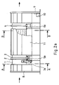
- Figs. 2a - 2c illustrate the barking drum unit.
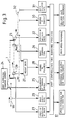
- Fig. 3 illustrates the principle of automatic control of a barking process by the procedure of the invention.
- Fig. 4 shows a barking drum unit as seen from that end where the delivery gate is located.
- In fig. 1, the amount of abrasion work is represented by the barking time and rotational speed of the drum, shown on the horizontal axis. It can be seen from the curve describing the degree of barking, which is based on points of observation, that the degree of barking of the logs increases as a function of the amount of abrasion work applied to them, as stated above.
- As shown in Fig. 2a, the barking drum unit comprises a
drum shell 1, amain gear ring 2, supportingrings structures 5a and 6a provided with supporting wheels and guide rollers,motor drives 7a rotating the drum, afeed end 8, adelivery end 9, adelivery gate 21, ahydraulic unit 10 for actuating the delivery gate, and abark conveyor 11. The logs move from left to right as indicated by the arrows. - The barking drum is typically a
cylinder 1 rotating on two bearings as indicated by the arrow in Figs. 2b (section A - A) and 2c (section B - B), inside which thelogs 12 move. The drum is provided withdevices structures device 13a is between the supportingwheels wheels 15c and 15d belonging to supporting structure 5b. In corresponding manner, measuringdevices 14a and 14b are placed in supportingstructures wheels measuring devices computer 17 which is provided with a control logic and performs the required calculations to determine the degree of fullness. Placed in the supporting structures 5a and 5b of one of the bearings are motor drives 18a and 18b provided with inverters and serving to rotate the barking drum. Power transmission from the motors to the barking drum occurs via themain gear ring 2. - The
conveyor 19 feeding the drum is provided withcapacity measurement 20 for measuring e.g. the weight of the logs on the conveyor and the conveyor speed. Thedelivery gate 21 of the drum is provided withmeans 22 for position indication. Furthermore, the drum is provided with aunit 23 for measuring the speed of rotation and aunit 25 for measuring thesupply 24 of thawing energy. Placed in conjunction with thebark conveyor 11 below the drum is aunit 26 for measuring the bark temperature. - The
weight data 27 for each drum end, obtained from the supportingstructures computer 17 which calculates the degree of fullness of the drum on the basis of the log distribution, determined by the aid of other process data. Based on the the degree of fullness, thecomputer 17 controls the position of thedelivery gate 21 so as to maintain a desired constant degree of fullness even when the feed capacity or speed of rotation of the drum varies. Before the drum is taken into use, the initial delivery gate position required by the intended degree of fullness is determined by performing trial runs with the equipment. The drum position data is obtained from the position indicator, which conists of apotentiometer 22 connected with thegate 21 by means of a thin thread (Fig. 4). As the gate moves, it pulls or releases the thread, so that thepotentiometer 22 is rotated correspondingly as a function of the gate position. In Fig. 4, the dotten boken line indicates the gate position corresponding to the amount of logs shown in the figure. Temporary changes in the degree of fullness can also be achieved by the control of the feed conveyor. - The bark temperature data is used to control the supply of thawing energy. This is also dependent on the data representing the degree of barking, which may prevent the supply of energy if the degree of barking is sufficient. The degree of barking can be determined by visual estimation by the operator, who inputs an estimate via the computer according to predefined rules. The degree of barking can also be determined automatically by using a CCD camera and image processing techniques known in themselves.
- The speed of rotation and feed capacity of the drum are utilized to achieve the desired degree of barking. This is done by operating the drum at a predetermined feed capacity and controlling the rotational speed in such a way that the desired degree of barking is achieved. The drum speed is controlled by means of the speed reference of the motor drives, which is given an initial value obtained on the basis of trials. By measuring the
wood delivery rate 31, it is also possible to control the drum speed so as to reduce the variations in the amounts of wood delivered onto theconveyor 32. - It is obvious to a person skilled in the art that different embodiments of the invention are not restricted to the examples described above, but that they may instead be varied within the scope of the claims presented below.
Claims (8)
- Procedure for controlling the barking process in a barking drum, using devices (13a,13b,14a,14b) measuring the weight of the drum, said devices being placed in conjunction with the barking drum (1), characterized in that- the measurment signals obtained from the weight measuring devices are used to calculate the degree of fullness of the drum,- the data representing the degree of fullness is used to control the position of the delivery gate (21) of the drum so as to achieve a desired degree of fullness,- the degree of barking of the logs is monitored, and- the data representing the degree of barking is used as a basis on which the speed of rotation of the drum is controlled.
- Procedure according to claim 1, characterized in that the degree of fullness is calculated with the aid of the measurement signals obtained from the weight measuring devices and of data representing the degree of density and packing of the logs.
- Procedure according to claim 1 or 2, characterized in that the speed of rotation is controlled to achieve a desired barking capacity.
- Procedure according to any one of the preceding claims, characterized in that the temperature of the bark is measured, and that the data representing the bark temperature and degree of barking are used to control the supply of the energy needed for the thawing of the logs.
- Apparatus designed for implementing the procedure of claim 1 for controlling the barking process in a barking drum, said drum comprising rotating equipment (18a-18d) for rotating the drum, which apparatus is provided with devices (13a,13b,14a,14b) measuring the weight of the drum, said said devices being placed in conjunction with the barking drum (1), characterized in that- the apparatus is provided with a computer (17) and a unit (22) for determining the position of the delivery gate (21) of the drum,- the computer is provided with inputs for the measurement signals obtained from the weight measuring devices to permit calculation of the degree of fullness,- the computer has an output providing a signal for controlling the position of the delivery gate of the drum, and an input for receiving a signal proportional to the position of the delivery gate to allow the desired degree of fullness to be achieved,- the computer is provided with appropriate connections to enable it to control the speed of rotation of the drum on the basis of data representing the degree of barking.
- Apparatus according to claim 5, characterized in that it is provided with a recognition means, such as a CCD camera, placed in conjunction with the delivery conveyor (32) of the barking drum and connected to the computer to allow monitoring of the degree of barking.
- Apparatus according to claim 5 or 6 for controlling the barking process in a barking drum provided with a supply (24) of energy for the thawing of the logs, characterized in that the apparatus has a unit (26) for measuring the temperature of the bark, and that the computer (17) controls the supply of the energy used for the thawing of the logs with the aid of the data representing the degree of barking and the bark temperature.
- Apparatus according to claim 5, 6 or 7, characterized in that the weight measuring devices are placed in the supporting structures (5a,5b,6a,6b) of the barking drum.
Applications Claiming Priority (3)
| Application Number | Priority Date | Filing Date | Title |
|---|---|---|---|
| FI902187A FI85238B (en) | 1990-05-02 | 1990-05-02 | FOERFARANDE OCH ANORDNING FOER STYRNING AV BARKNINGSPROCESS. |
| FI902187 | 1990-05-02 | ||
| PCT/FI1991/000125 WO1991017030A1 (en) | 1990-05-02 | 1991-04-29 | Procedure and apparatus for controlling a barking process |
Publications (2)
| Publication Number | Publication Date |
|---|---|
| EP0592408A1 EP0592408A1 (en) | 1994-04-20 |
| EP0592408B1 true EP0592408B1 (en) | 1995-11-08 |
Family
ID=8530353
Family Applications (1)
| Application Number | Title | Priority Date | Filing Date |
|---|---|---|---|
| EP91908453A Revoked EP0592408B1 (en) | 1990-05-02 | 1991-04-29 | Procedure and apparatus for controlling a barking process |
Country Status (9)
| Country | Link |
|---|---|
| US (1) | US5247978A (en) |
| EP (1) | EP0592408B1 (en) |
| AT (1) | ATE129949T1 (en) |
| CA (1) | CA2063377C (en) |
| DE (1) | DE69114522T2 (en) |
| FI (1) | FI85238B (en) |
| LT (1) | LT3402B (en) |
| RU (1) | RU2080252C1 (en) |
| WO (1) | WO1991017030A1 (en) |
Cited By (1)
| Publication number | Priority date | Publication date | Assignee | Title |
|---|---|---|---|---|
| CN104476644A (en) * | 2014-12-11 | 2015-04-01 | 济南职业学院 | Wood defrosting equipment |
Families Citing this family (15)
| Publication number | Priority date | Publication date | Assignee | Title |
|---|---|---|---|---|
| FI89336C (en) * | 1992-09-03 | 1993-09-27 | Yhtyneet Paperitehtaat Oy | FOERFARANDE I EN BARKNINGSPROCESS AV VIRKE |
| SE506160C2 (en) * | 1994-11-23 | 1997-11-17 | Bmh Wood Technology Ab | Barking device assembly |
| US5481965A (en) * | 1995-04-21 | 1996-01-09 | Natural Grilling & Fuel Systems, Inc. | Rack and screen assembly for converting gas grilles into charcoal and/or wood burning grilles |
| US6161534A (en) * | 1997-07-23 | 2000-12-19 | Kronman; Leonard | Method and apparatus for converting a gas grill and/or charcoal burning grill |
| US5803142A (en) * | 1997-09-08 | 1998-09-08 | Westvaco Corporation | Debarking and chipping folded whole-trees |
| US5868186A (en) * | 1997-09-11 | 1999-02-09 | Westvaco Corporation | Debarking wood without introducing contaminants into the wood |
| WO2002055968A1 (en) * | 2000-12-04 | 2002-07-18 | Metso Woodhandling Oy | Method of measuring the filling degree of filling in a debarking drum |
| FI20010664L (en) * | 2001-03-30 | 2002-10-01 | Metso Paper Inc | Drum peeling control method |
| FI20021134A7 (en) * | 2002-06-12 | 2003-12-13 | Metso Paper Inc | Drum peeling method and separation of bark from the wood stream |
| FI20025065A7 (en) * | 2002-12-18 | 2004-06-19 | Andritz Oy | Method for optimizing the debarking result of trees being debarked in a debarking drum |
| US7431060B2 (en) * | 2003-10-02 | 2008-10-07 | The Price Companies, Inc. | Automatic fiber yield system and method |
| FI20055558A0 (en) * | 2005-10-18 | 2005-10-18 | Metso Paper Inc | Control function for a pulpwood decomposition drum |
| FI122576B (en) * | 2007-06-27 | 2012-03-30 | Teknosavo Oy | Method and apparatus for measuring the degree of filling of a barking drum |
| CA2780202C (en) | 2012-06-19 | 2014-11-18 | Centre De Recherche Industrielle Du Quebec | Method and system for detecting the quality of debarking at the surface of a wooden log |
| SE543059C2 (en) * | 2019-03-07 | 2020-09-29 | Stora Enso Oyj | Device and method of processing logs using a thermal camera |
Family Cites Families (6)
| Publication number | Priority date | Publication date | Assignee | Title |
|---|---|---|---|---|
| US3807469A (en) * | 1972-07-24 | 1974-04-30 | A Schnyder | Barking apparatus and process therefor |
| US4173239A (en) * | 1977-07-12 | 1979-11-06 | Chicago Bridge & Iron Company | Method of and apparatus for controlling the flow of materials from a rotating drum |
| SE430483B (en) * | 1982-03-19 | 1983-11-21 | Karlstad Mekaniska Ab | debarking drum |
| FI76723C (en) * | 1983-12-22 | 1988-12-12 | Rauma Repola Oy | FOERFARANDE FOER ATT STAENGA AV REGLERINGSPORTEN TILL EN BARKNINGSTRUMMA, OCH PORT FOER UTFOERANDE AV FOERFARANDET. |
| SE454758B (en) * | 1984-04-06 | 1988-05-30 | Kone Oy | Timber raw material processing |
| US5019123A (en) * | 1990-07-03 | 1991-05-28 | Ingersoll-Rand Company | Pulp log discharge system for a debarking drum |
-
1990
- 1990-05-02 FI FI902187A patent/FI85238B/en not_active Application Discontinuation
-
1991
- 1991-04-29 DE DE69114522T patent/DE69114522T2/en not_active Revoked
- 1991-04-29 WO PCT/FI1991/000125 patent/WO1991017030A1/en not_active Ceased
- 1991-04-29 CA CA002063377A patent/CA2063377C/en not_active Expired - Fee Related
- 1991-04-29 US US07/835,464 patent/US5247978A/en not_active Expired - Lifetime
- 1991-04-29 RU SU915010954A patent/RU2080252C1/en active
- 1991-04-29 EP EP91908453A patent/EP0592408B1/en not_active Revoked
- 1991-04-29 AT AT91908453T patent/ATE129949T1/en not_active IP Right Cessation
-
1993
- 1993-06-23 LT LTIP697A patent/LT3402B/en not_active IP Right Cessation
Cited By (1)
| Publication number | Priority date | Publication date | Assignee | Title |
|---|---|---|---|---|
| CN104476644A (en) * | 2014-12-11 | 2015-04-01 | 济南职业学院 | Wood defrosting equipment |
Also Published As
| Publication number | Publication date |
|---|---|
| DE69114522T2 (en) | 1996-04-18 |
| LT3402B (en) | 1995-09-25 |
| EP0592408A1 (en) | 1994-04-20 |
| CA2063377A1 (en) | 1991-11-03 |
| ATE129949T1 (en) | 1995-11-15 |
| LTIP697A (en) | 1995-01-31 |
| DE69114522D1 (en) | 1995-12-14 |
| FI902187A0 (en) | 1990-05-02 |
| RU2080252C1 (en) | 1997-05-27 |
| US5247978A (en) | 1993-09-28 |
| WO1991017030A1 (en) | 1991-11-14 |
| CA2063377C (en) | 1996-05-07 |
| FI85238B (en) | 1991-12-13 |
| FI902187A7 (en) | 1991-11-03 |
Similar Documents
| Publication | Publication Date | Title |
|---|---|---|
| US5247978A (en) | Procedure and apparatus for controlling a barking process | |
| EP1490547B1 (en) | Method for defibring recycled fibre material in a drum pulper, and a drum pulper | |
| CA1269591A (en) | Method of and apparatus for feeding roundwood into a rotating barking drum | |
| US3385331A (en) | Branch removing machine | |
| FI65288B (en) | ANORDNING VID MALAPPARATER LIGNOCELLULOSAHALTIGT MATERIAL | |
| LV11015B (en) | Method and device for controlling the peeling process | |
| US6360796B1 (en) | Wood working machine | |
| US7431060B2 (en) | Automatic fiber yield system and method | |
| NO844132L (en) | LUFTKNIVBESTRYKER | |
| FI69981B (en) | Hugg | |
| NO790524L (en) | PROCEDURE FOR PREPARING MASS | |
| US2600625A (en) | Log supporting and log manipulating device for wood debarking devices | |
| CA1063406A (en) | Method and apparatus for producing fiber pulp in a steam-pressurized grinding apparatus | |
| US2581617A (en) | Device for barking of logs or the like | |
| GB2250905A (en) | Improvements relating to fodder distribution devices | |
| US663211A (en) | Wood-barking machine. | |
| FI78638B (en) | FOERFARANDE OCH ANORDNING FOER AVLASTNING AV TRAE I EN BARKNINGSTRUMME OCH FOER MATNING TILL EN FLISHUGG. | |
| GB1571687A (en) | Method of and apparatus for making a cellulose fibre batt | |
| US915919A (en) | Wood-rosser. | |
| BRPI0617457A2 (en) | wood processing appliance to be reduced to chips | |
| US20060272745A1 (en) | Method for optimizing the debarking result of logs debarked in a debarking drum | |
| SU1113445A1 (en) | Method of controlling process of milling fibrous materials in rolls | |
| SE535557C2 (en) | Process for making chips | |
| SE9500699L (en) | Process of timber barking process | |
| SE177717C1 (en) |
Legal Events
| Date | Code | Title | Description |
|---|---|---|---|
| PUAI | Public reference made under article 153(3) epc to a published international application that has entered the european phase |
Free format text: ORIGINAL CODE: 0009012 |
|
| 17P | Request for examination filed |
Effective date: 19920113 |
|
| AK | Designated contracting states |
Kind code of ref document: A1 Designated state(s): AT BE CH DE DK ES FR GB GR IT LI LU NL SE |
|
| 17Q | First examination report despatched |
Effective date: 19950126 |
|
| RAP1 | Party data changed (applicant data changed or rights of an application transferred) |
Owner name: ANDRITZ-PATENTVERWALTUNGS-GESELLSCHAFT M.B.H. |
|
| GRAA | (expected) grant |
Free format text: ORIGINAL CODE: 0009210 |
|
| AK | Designated contracting states |
Kind code of ref document: B1 Designated state(s): AT BE CH DE DK ES FR GB GR IT LI LU NL SE |
|
| PG25 | Lapsed in a contracting state [announced via postgrant information from national office to epo] |
Ref country code: IT Free format text: LAPSE BECAUSE OF FAILURE TO SUBMIT A TRANSLATION OF THE DESCRIPTION OR TO PAY THE FEE WITHIN THE PRE;WARNING: LAPSES OF ITALIAN PATENTS WITH EFFECTIVE DATE BEFORE 2007 MAY HAVE OCCURRED AT ANY TIME BEFORE 2007. THE CORRECT EFFECTIVE DATE MAY BE DIFFERENT FROM THE ONE RECORDED.SCRIBED TIME-LIMIT Effective date: 19951108 Ref country code: DK Effective date: 19951108 Ref country code: LI Effective date: 19951108 Ref country code: BE Effective date: 19951108 Ref country code: GR Free format text: LAPSE BECAUSE OF FAILURE TO SUBMIT A TRANSLATION OF THE DESCRIPTION OR TO PAY THE FEE WITHIN THE PRESCRIBED TIME-LIMIT Effective date: 19951108 Ref country code: CH Effective date: 19951108 Ref country code: NL Free format text: LAPSE BECAUSE OF FAILURE TO SUBMIT A TRANSLATION OF THE DESCRIPTION OR TO PAY THE FEE WITHIN THE PRESCRIBED TIME-LIMIT Effective date: 19951108 |
|
| REF | Corresponds to: |
Ref document number: 129949 Country of ref document: AT Date of ref document: 19951115 Kind code of ref document: T |
|
| REF | Corresponds to: |
Ref document number: 69114522 Country of ref document: DE Date of ref document: 19951214 |
|
| ET | Fr: translation filed | ||
| PG25 | Lapsed in a contracting state [announced via postgrant information from national office to epo] |
Ref country code: ES Free format text: LAPSE BECAUSE OF FAILURE TO SUBMIT A TRANSLATION OF THE DESCRIPTION OR TO PAY THE FEE WITHIN THE PRESCRIBED TIME-LIMIT Effective date: 19960209 |
|
| NLV1 | Nl: lapsed or annulled due to failure to fulfill the requirements of art. 29p and 29m of the patents act | ||
| PG25 | Lapsed in a contracting state [announced via postgrant information from national office to epo] |
Ref country code: GB Effective date: 19960429 |
|
| PG25 | Lapsed in a contracting state [announced via postgrant information from national office to epo] |
Ref country code: LU Free format text: LAPSE BECAUSE OF NON-PAYMENT OF DUE FEES Effective date: 19960430 |
|
| REG | Reference to a national code |
Ref country code: CH Ref legal event code: PL |
|
| PLBQ | Unpublished change to opponent data |
Free format text: ORIGINAL CODE: EPIDOS OPPO |
|
| PLBI | Opposition filed |
Free format text: ORIGINAL CODE: 0009260 |
|
| PLBF | Reply of patent proprietor to notice(s) of opposition |
Free format text: ORIGINAL CODE: EPIDOS OBSO |
|
| 26 | Opposition filed |
Opponent name: SUNDS DEFIBRATOR WOODHANDLING OY Effective date: 19960801 |
|
| GBPC | Gb: european patent ceased through non-payment of renewal fee |
Effective date: 19960429 |
|
| PLBF | Reply of patent proprietor to notice(s) of opposition |
Free format text: ORIGINAL CODE: EPIDOS OBSO |
|
| PLBF | Reply of patent proprietor to notice(s) of opposition |
Free format text: ORIGINAL CODE: EPIDOS OBSO |
|
| PGFP | Annual fee paid to national office [announced via postgrant information from national office to epo] |
Ref country code: AT Payment date: 20010309 Year of fee payment: 11 |
|
| PGFP | Annual fee paid to national office [announced via postgrant information from national office to epo] |
Ref country code: FR Payment date: 20010312 Year of fee payment: 11 |
|
| PGFP | Annual fee paid to national office [announced via postgrant information from national office to epo] |
Ref country code: DE Payment date: 20010321 Year of fee payment: 11 |
|
| RDAH | Patent revoked |
Free format text: ORIGINAL CODE: EPIDOS REVO |
|
| RDAG | Patent revoked |
Free format text: ORIGINAL CODE: 0009271 |
|
| STAA | Information on the status of an ep patent application or granted ep patent |
Free format text: STATUS: PATENT REVOKED |
|
| PGFP | Annual fee paid to national office [announced via postgrant information from national office to epo] |
Ref country code: SE Payment date: 20020319 Year of fee payment: 12 |
|
| 27W | Patent revoked |
Effective date: 20000125 |