EP0592030B1 - Electromechanical displacement device and actuator suitable for use in such an electromechanical displacement device - Google Patents
Electromechanical displacement device and actuator suitable for use in such an electromechanical displacement device Download PDFInfo
- Publication number
- EP0592030B1 EP0592030B1 EP93202747A EP93202747A EP0592030B1 EP 0592030 B1 EP0592030 B1 EP 0592030B1 EP 93202747 A EP93202747 A EP 93202747A EP 93202747 A EP93202747 A EP 93202747A EP 0592030 B1 EP0592030 B1 EP 0592030B1
- Authority
- EP
- European Patent Office
- Prior art keywords
- clamping
- clamping members
- shaft
- displacement device
- actuator
- Prior art date
- Legal status (The legal status is an assumption and is not a legal conclusion. Google has not performed a legal analysis and makes no representation as to the accuracy of the status listed.)
- Expired - Lifetime
Links
- 238000006073 displacement reaction Methods 0.000 title claims description 68
- 239000000463 material Substances 0.000 claims description 17
- 230000004913 activation Effects 0.000 claims description 7
- 230000008878 coupling Effects 0.000 claims description 5
- 238000010168 coupling process Methods 0.000 claims description 5
- 238000005859 coupling reaction Methods 0.000 claims description 5
- 230000009849 deactivation Effects 0.000 claims description 5
- 230000009471 action Effects 0.000 description 11
- 230000008859 change Effects 0.000 description 5
- 230000006835 compression Effects 0.000 description 4
- 238000007906 compression Methods 0.000 description 4
- 238000004519 manufacturing process Methods 0.000 description 4
- 230000007423 decrease Effects 0.000 description 3
- 239000002184 metal Substances 0.000 description 3
- 238000010586 diagram Methods 0.000 description 2
- 238000009760 electrical discharge machining Methods 0.000 description 2
- 229910000906 Bronze Inorganic materials 0.000 description 1
- 238000005452 bending Methods 0.000 description 1
- 230000008901 benefit Effects 0.000 description 1
- 239000010974 bronze Substances 0.000 description 1
- 238000010276 construction Methods 0.000 description 1
- KUNSUQLRTQLHQQ-UHFFFAOYSA-N copper tin Chemical compound [Cu].[Sn] KUNSUQLRTQLHQQ-UHFFFAOYSA-N 0.000 description 1
- 239000003292 glue Substances 0.000 description 1
- 238000003698 laser cutting Methods 0.000 description 1
- 238000003825 pressing Methods 0.000 description 1
- 238000004904 shortening Methods 0.000 description 1
Images


Classifications
-
- H—ELECTRICITY
- H02—GENERATION; CONVERSION OR DISTRIBUTION OF ELECTRIC POWER
- H02N—ELECTRIC MACHINES NOT OTHERWISE PROVIDED FOR
- H02N2/00—Electric machines in general using piezoelectric effect, electrostriction or magnetostriction
- H02N2/02—Electric machines in general using piezoelectric effect, electrostriction or magnetostriction producing linear motion, e.g. actuators; Linear positioners ; Linear motors
- H02N2/021—Electric machines in general using piezoelectric effect, electrostriction or magnetostriction producing linear motion, e.g. actuators; Linear positioners ; Linear motors using intermittent driving, e.g. step motors, piezoleg motors
- H02N2/023—Inchworm motors
Definitions
- the invention relates to an electromechanical displacement device provided with a holder, an element displaceable relative to the holder, and an actuator connected to the holder and capable of displacing the element relative to the holder, which actuator is provided with at least a first and a second clamping member which are arranged separately from one another and can be clamped against the displaceable element, while at least one of the clamping members is provided with a clamping element of transducer material, and which actuator is further provided with a transport element of transducer material by which a distance between the clamping members can be changed while one clamping member is connected to the element with clamping force.
- clamping member in the present Patent Application is understood to mean at least one surface which can be clamped against the element to be displaced in that the distance between the surface and the element can be reduced.
- a “series of clamping members” means at least two surfaces between which the element to be displaced can be clamped in that the distance between the surfaces can be reduced.
- transducer material is understood to mean a material which changes its shape under the influence of a change in an electric or magnetic field, for example, piezoelectric materials, electrostrictive materials or magnetostrictive materials.
- annular piezoelectric transport element 1 is connected on opposing sides to two annular piezoelectric clamping elements 3, 5 (two clamping members) which can be clamped against a shaft 7.
- the piezoelectric transport element 1 is connected to a holder 9.
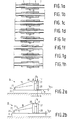
- the piezoelectric elements can be separately activated by a voltage source. Activation reduces the internal diameters of the clamping elements 3 and 5, while it increases the length of the transport element 1 in axial direction. In situation (a) depicted in Fig. 1, all piezoelectric elements are deactivated. In situation (b), clamping element 3 is activated and clamps around the shaft 7. In situation (c), subsequently, transport element 1 is activated, whereby it increases in length, so that the clamping element 3 together with the shaft 7 is moved to the left. Then clamping element 5 is activated (d), so that the elements 3 and 5 are simultaneously clamped against the shaft. After this the clamping element 3 is deactivated (e) so that the clamping element 3 no longer clamps against the shaft 7.
- the transport element 1 is deactivated (f), so that it decreases in length and the clamping element 5 together with the shaft 7 is moved to the left.
- the two elements 3 and 5 are activated in situation (g), and in situation (h) the clamping action of element 5 is discontinued, upon which the situation is identical again to the situation (b).
- the steps (b) to (g) should be repeated as often as is necessary.
- the diameter changes of annular piezoelectric clamping elements which can be realised in practice are only small, so that high requirements are imposed on the accuracy of the shaft diameter, or else the clamping elements may be continually clamped around the shaft or may be incapable of being clamped around the shaft at all.
- the invention has for its object to provide a displacement device with which the said disadvantages are avoided.
- the electromechanical displacement device is for this purpose characterized in that the displacement device is provided with means for exerting a mechanical pretensioning force on the actuator, the mechanical pretensioning force being transmitted to the first clamping member to clamp the first clamping member against the displaceable element with said mechanical pretensioning force while the second clamping member is disengaged from the displaceable element through deactivation of the clamping element, and the mechanical pretensioning force being transmitted to the second clamping member to clamp the second clamping member against the displaceable element with the mechanical pretensioning force while the first clamping member is disengaged from the displaceable element through activation of the clamping element.
- the mechanical pretensioning force may be provided by means of a spring or a mechanical construction.
- the mechanical pretensioning force provides a constant clamping force of the clamping members on the element to be displaced which is comparatively independent of the accuracy of the dimension of the element present between the clamping members.
- the displacement device is no longer sensitive to expansion of the element and the clamping members resulting from temperature changes.
- the clamping members are moved toward the element under the mechanical pretensioning force in the case of wear of the clamping members, and it remains possible to press the clamping members against the element to be displaced.
- a high manufacturing accuracy of the element has also become unnecessary for a good clamping action of the clamping members.
- the distance over which the element can be displaced is no longer limited by manufacturing accuracies.
- the mechanical pretensioning force in the displacement device always presses a single clamping member or a single series of clamping members against the element at any time.
- the distance between the clamping member or series of clamping members pressing against the element is increased by means of the clamping element, so that the clamping member or series of clamping members becomes disengaged from the element.
- the mechanical pretensioning force presses the other clamping member or series of clamping members against the element to be displaced. In principle, there is never more than a single clamping member or single of clamping members which presses against the element.
- the clamping force is exerted by the clamping elements, while the dimensional changes of the clamping elements and the shape of the shaft are determining factors for a good clamping action. If the clamping action is to be switched between the clamping elements, both clamping elements should be subject to a dimensional change each time.
- the absolute dimension of the element to be displaced at the area of the clamping members is important for a good clamping action, whereas in the device according to the invention the dimensional difference of the element between the area of the first clamping member and the area of the second clamping member is important for a good clamping action.
- An embodiment of the displacement device according to the invention is characterized in that the distance between the clamping members is smaller than a length of the transport element seen in a direction in which the transducer material of the transport element is lengthened or shortened by activation or deactivation of the transport element.
- the transport element does not lie between the clamping members here, as in the device according to the cited US Patent, but next to or outside these clamping members.
- the spacing between the clamping members may be chosen to be as small as possible, so that the dimensional difference of the element to be displaced between the area of the first clamping member and at the area of the second clamping member is small in practice.
- the rigidity of the actuator between the clamping members can then be made comparatively great in a simple manner. In the case of a comparatively small rigidity of the actuator, in fact, there is the risk that the necessary spacing between the disengaged clamping member and the element to be displaced is lost owing to deformations of the actuator and both clamping members remain permanently in contact with the element to be displaced.
- the length of the transport element has no influence on the spacing between the clamping members, and the length of the transport element may be determined independently of the desired displacement of the element.
- a further embodiment of the displacement device according to the invention in which the element is a round shaft, is characterized in that the actuator is provided with two series of clamping members which are interconnected by means of a ring which concentrically surrounds the shaft and which is provided with plate-shaped bridges which lie between clamping members of a single series, which are flexible in radial direction relative to the shaft, and by which the pretensioning force is transmitted to the clamping members, and in that the actuator is provided with plate-shaped coupling pieces situated between clamping members of different series and flexible in axial direction relative to the shaft.
- the interspacing in axial direction between the clamping members is reduced to a minimum here, so that dimensional tolerances in axial direction of the shaft have a minimum influence on the operation of the displacement device.
- Each clamping member is displaceable in axial direction to beyond the other clamping member. As a result, the displacement device as it were "creeps" over the shaft.
- An alternative embodiment of the displacement device according to the invention is characterized in that the actuator is provided with only one single clamping element by which the clamping members are alternately clamped against the displaceable element.
- a comparatively inexpensive displacement device is obtained in this way.
- This embodiment is especially suitable for displacing flexible elements which are deformable between the clamping members.
- a yet further embodiment of the displacement device according to the invention is characterized in that the transport element is provided with a carrier connected to the holder and with two piezoelectric transport elements of equal length made of transducer material, one of these piezoelectric transport elements being situated between the carrier and the first clamping member, while the other piezoelectric transport element is situated between the carrier and the second clamping member.
- the use of two piezoelectric transport elements of transducer material in the transport element renders possible a displacement of the displaceable element between each alternation of the clamping force from the one to the other clamping member, by which a regular displacement is obtained seen in time.
- Each piezoelectric transport element can be fastened to the carrier in a simple manner owing to the use of two piezoelectric transport elements.
- Fig. 1 shows a device known from US-A 3902084 whose operation was described in the introductory paragraphs of the present document.
- Figs. 2a and 2b diagrammatically show the clamping principle according to the invention.
- the piezoelectric transport element by means of which the clamping members can be displaced relative to one another is not depicted in Figs. 2a and 2b for simplicity's sake. This element, however, is shown in Figs. 3, 4 and 6.
- Figs. 2a and 2b show a plate 11 in fixed position on which an actuator 15 is mounted.
- the actuator 15 comprises two clamping members A and B which are interconnected by a bridge 17.
- the clamping members A and B and the bridge 17 are connected to a support 23 via a lever 19 and a pivot 21.
- the clamping member B comprises a pin 25, while the clamping member A is provided with a pin 27 and a piezoelectric clamping element 29 fastened to the pin 27.
- the pin 25 and the clamping element 29 each have a flat end face acting as a clamping surface at the end facing the plate.
- a mechanical pretensioning force F k is exerted via the bridge 17, so that the lever 19 rotates in the pivot 21 until one clamping member is pressed against the plate 11 by the clamping force F k .
- the clamping member B is pressed against the plate 11 by the force F k , while the clamping member A lies at a distance 1 ⁇ 2s from the plate.
- the piezoelectric clamping element 29 is electrically activated in a usual manner so that the element 29 becomes longer by at least a length s and makes contact with the plate 11, whereby the lever 19 is rotated in a direction indicated by arrow 31 and the clamping member B becomes detached from the plate 11 (see Fig. 2b).
- s may be, for example, 4 ⁇ m.
- the compression force F k now presses the clamping member A against the plate 11.
- the clamping member B is again pressed against the plate 11 owing to the return of the lever 19 by the compression force F k .
- both the interspacing between the clamping members A and B and the stiffness of the displacement device are so chosen that a single series of clamping members is pressed against the element to be displaced at any time.
- the actuator 15 shown in Figs. 2a and 2b is insensitive to thickness variations for which the difference in thickness between the clamping members remains comparatively small. If the thickness change gradient is comparatively small, only one clamping member A or B will be pressed against the plate 11 by the compression force F k at any time owing to rotation of the lever 19 about the pivot 21. This also takes place when the plate 11 increases in thickness owing to a temperature rise.
- the actuator Given an even wear of the clamping members A and B, the actuator will continue to operate provided the spacing between the plate and the disengaged clamping member remains approximately 1 ⁇ 2s.
- the activation of only a single piezoelectric clamping element suffices for switching the clamping force from the one to the other clamping member.
- both clamping elements 3 and 5 must be activated in order to switch over the clamping force.
- the clamping member B may be provided with a piezoelectric clamping element in order to increase the length difference between the clamping members A and B to be realised, whereby the displacement device becomes even more insensitive to thickness tolerances.
- Fig. 3 shows a displacement device 41 according to the invention.
- the displacement device 41 is provided with an actuator 43 and a round shaft 45 which can be displaced by means of the actuator.
- the actuator 43 is provided with a bush 47 in which the shaft 45 is supported at one side by means of a bronze sleeve bearing bush 49.
- the bush 47 was formed from an original thin-walled cylinder which was cut into two bush parts 51, 53 by laser cutting, each bush part 51, 53 being provided with a comb having a number of interleaved fingers 55, 57 acting as blade springs.
- the bush part 51 has three fingers 55 each provided with a piezoelectric clamping element 59.
- the bush part 53 has six fingers 57 each provided with a piezoelectric clamping element 61.
- the clamping elements 59 and 61 are made of the same piezoelectric material, the width b1 of the clamping element 59 being twice the width b2 of the clamping element 61.
- the three clamping elements 59 constitute a first series of clamping elements, while the six clamping elements 61 constitute a second series of clamping members.
- the clamping members at the same time act as a bearing for the shaft 45 in radial direction.
- the clamping elements 59, 61 are fastened on the fingers 55, 57 by means of glue.
- the clamping elements 59 and 61 are interconnected by means of a clamping ring 63 glued to the clamping elements 59, 61.
- the clamping ring 63 is provided with plate-shaped coupling pieces 65 between the clamping elements 59 and the clamping elements 61. Owing to a comparatively large dimension in radial direction and a comparatively small dimension in axial direction, the plate-shaped coupling pieces 65 are rigid in the radial direction, while a mutual axial movement of the series of clamping members is possible.
- the clamping elements 61 are mutually interconnected by means of three plate-shaped bridges 67 which are comparatively thin in radial direction and comparatively wide in axial direction.
- the length of the plate-shaped bridges 67 in tangential direction is so chosen that, after the actuator 43 has been mounted on the shaft 45, the bridges are slightly stretched and bent in radial direction, so that the fingers of a bush part are pressed against the shaft 45 under a mechanical pretensioning force.
- the bush parts 51 and 53 are interconnected by means of three piezoelectric transport elements 69 glued to the ends of the bush parts 51 and 53. When the piezoelectric clamping elements 59, 61 and 69 are activated, the length of the clamping elements 59 and 61 in radial direction and the length of the transport elements 69 in axial direction increase.
- Activation of the piezoelectric elements may take place in a manner known per se such as described, for example, in US-A 3902084.
- the actuator 43 may, for example, be fastened to a holder (not shown) by the portion 71 of the clamping ring 63 fastened to the clamping elements 59.
- the holder may be, for example, a housing of a machine or a device.
- the operation of the displacement device 41 will be explained briefly, starting from a situation in which the portions 71 are fixedly connected to a stationary holder and the fingers 55 are pressed against the shaft 45 by the activated piezoelectric clamping elements 59, while the piezoelectric clamping elements 61 are not activated. The distance between the fingers 57 and the shaft then is s .
- the clamping elements 59 are longer than the clamping elements 61 by a length s . Then the piezoelectric transport elements 69 are activated, so that they become longer, and the bush part 53 is moved in the direction of the arrow 73. After that the piezoelectric clamping elements 61 are activated and become longer by a length s , while the clamping elements 59 are deactivated and become shorter by a length s . The mechanical pretensioning force is transferred thereby to the clamping elements 61, so that the fingers 57 are pressed against the shaft 45. The difference in length between the clamping elements 59 and 61 then is s .
- the piezoelectric transport elements 69 are deactivated, so that the length of these elements decreases, and the bush part 53 together with the shaft 45 is moved in the direction of the arrow 75.
- the clamping elements 61 are displaced in axial direction during this from a position to the left of the clamping elements 59 to a position to the right of the clamping elements 59.
- the mechanical pretensioning force is transferred again to the clamping elements 59, and the cycle described above is repeated, whereby the shaft is further displaced in the direction of the arrow 75.
- the piezoelectric transport elements 69 should be lengthened when the fingers 57 are pressed against the shaft 45 by the clamping elements 61, and should be shortened when the fingers 55 are pressed against the shaft by the clamping elements 59.
- the clamping members of both series in the displacement device 41 are provided with piezoelectric clamping elements. This has the advantage that the length difference to be realised between the clamping elements 59 and 61 is twice as large as in the case in which the clamping members of only one series of clamping members are provided with piezoelectric clamping elements. Greater diameter tolerances for the shaft and/or a lower rigidity of the actuator are admissible as a result.
- the displacement device 41 also functions when the clamping members of only one series of clamping members are provided with piezoelectric clamping elements.
- Fig. 4 shows a second embodiment of a displacement device according to the invention.
- the displacement device 81 is provided with an actuator 83 and a round shaft 45 to be displaced by means of the actuator 83.
- the actuator 83 is provided with a metal plate 85 in which slots are provided by wire spark erosion such that various portions of the plate 85 can be displaced over a comparatively small distance and/or rotated through a comparatively small angle relative to one another.
- the actuator 83 is further provided with two piezoelectric clamping elements 61 by which a series of clamping members A can be pressed against the shaft 45 and with two piezoelectric transport elements 69', 69'' of equal length by which a displacement of the series of clamping members A relative to a second series of clamping members B can be effected.
- the clamping members A or B are pressed against the shaft 45 under a mechanical pretensioning force, this mechanical pretensioning force F k being provided by means of a tension spring (not shown) which is fastened in holes 87' and 87".
- the mechanical compression force F k is between 1 and 100 N.
- the holes 87' and 87'' are provided in respective plate portions 85a and 85b which are rotatable relative to one another about a so-called elastic hinge 89. Bores in the plate portions 85c and 85d are fitted with sleeve bearing bushes for the shaft 45. Plate portion 85e acts as a carrier which is connected to a holder 90 through the holes 91.
- the transport elements 69' and 69'' connected to the carrier 85e are under a mechanical pretensioning force F o which is provided by means of a tension spring (not shown) fastened in holes 93' and 93'' in respective plate portions 85c and 85f.
- the pretensioning force F o prevents the transport elements 69' and 69'' from being loaded with tensional force.
- Each series of clamping members is provided with two flat surfaces which are displaceable relative to one another and which can be clamped against the shaft 45.
- series A is provided with the clamping surfaces 95 and series B with the clamping surfaces 97.
- the clamping elements 61 are activated, so that they increase in length.
- elastic hinges 99 are displaced in the direction of the arrow 75, whereby the plate portions 85g and 85h are rotated about the elastic hinges 99, 101, 103 and displace the elastic hinges 101 towards the shaft and the elastic hinges 103 away from the shaft.
- the clamping surfaces 95 of the clamping member series A are pressed against the shaft by this. since the plate portions 85g and 85h are at an angle ⁇ of +45° and -45°, respectively, relative to the direction 75 in which the elastic hinge 99 is moved, the increase in the distance between the elastic hinges 101 and 103 is approximately twice (2*tan ⁇ ) as great as the length change of the clamping element 61.
- Displacement of the series of clamping members A relative to the series of clamping members B is realised by means of the two transport elements 69' and 69".
- plate portion 85c is rotated about elastic hinge 105 in the direction of the arrow 73 when the transport element 69'' is lengthened, and the clamping surfaces 95 of the series of clamping members A, which are connected to the plate portion 85c inter alia via elastic hinge 170, are also displaced in the direction of the arrow 73.
- the displacement of the clamping surfaces 95 is (L1 +L2)/L2 times the lengthening of the transport element 69''.
- a radial displacement of the clamping surfaces 97 relative to one another is possible through the elastic hinge 113.
- An axial displacement of the clamping surfaces 97 relative to the clamping surfaces 95 is also possible by means of the elastic hinges 115 on either side of plate portions 85k.
- the operation of the displacement device 81 is now explained briefly, starting from a situation in which the carrier 85e is stationary and the clamping surfaces 97 of the clamping members B are pressed againt the shaft 45.
- the distance between the clamping surfaces 95 and the shaft 45 is 1 ⁇ 2s.
- the transport element 69'' is lengthened while the transport element 69' is shortened. This moves the freed clamping members A in the direction of the arrow 73 and the clamping members B together with the shaft 45 in the direction of the arrow 75.
- the piezoelectric clamping elements 61 are activated, whereby the mechanical pretensioning force F k is transferred to the series of clamping members A, the clamping surfaces 95 being pressed against the shaft 45.
- the distance between the elastic hinges 101 and 103 becomes greater by a lenth s , so that the spacing between the clamping surfaces of the clamping members B becomes 1 ⁇ 2s. Then the transport element 69' is lengthened, whikle the transport element 69'' is shortened. The freed clamping members B are moved in the direction of the arrow 73 by this, and the clamping members A together with the shaft 45 are moved in the direction of the arrow 75. subsequently, the mechanical pretensioning force is transferred to the clamping surfaces 97 again, and the cycle described above is repeated, so that the shaft 45 is moved further in the direction of the arrow 75.
- the transport element 69' is to be lengthened and the transport element 69'' to be shortened at the moment at which the clamping members B are pressed against the shaft 45, while the transport element 69'' is to be lengthened and the transport element 69' to be shortened at the moment at which the clamping members A are pressed against the shaft 45.
- both series of clamping members A and B are connected to the stationary carrier 85e via a piezoelectric transport element, a displacement is carried out by the shaft 45 both during clamping of series A and during clamping of series B.
- the displacement of the shaft 45 as seen in time is more regular than if a displacement of the shaft were carried out only during clamping of one series of clamping members.
- Fig. 5 shows time diagrams of voltages U 61 , U 69'' and U 69' at the clamping elements 61 and the transport elements 69'' and 69', respectively, of the clamping actions of the clamping members A and B, and of the displacement X A , X B and X 45 of the clamping members A and B and the shaft 45 to be displaced, respectively, of the device depicted in Fig. 4.
- the clamping members A clamp against the shaft 45 and the shaft 45 together with the clamping members A is displaced in the X-direction corresponding to the arrow 73.
- Fig. 6 shows a third embodiment of a displacement device according to the invention.
- the displacement device 131 is provided with an actuator 123 and a flexible metal plate 125 which can be displaced by means of the actuator 123.
- the actuator 123 comprises a metal plate 127 in which slots are provided by wire spark erosion so that various portions of the plate 127 are displaceable over a comparatively small distance and/or rotatable through a comparatively small angle relative to one another.
- the actuator 127 is further provided with a single piezoelectric clamping element 61 by which a series of clamping members A can be pressed against the flexible plate 125, and provided with a single piezoelectric transport element 69 by which a displacement of the series of clamping members A relative to a second series of clamping members B can be carried out.
- the clamping members A, B have flat end faces acting as clamping surfaces at their ends facing the plate 125.
- the clamping members are pressed against the plate 125 under a mechanical pretensioning force F k by means of a tension spring 128 fastened in holes 129' and 129".
- the tension spring 128 also provides a pretensioning force on the transport element 69.
- the holes 129' and 129" are provided in respective plate portions 127a and 127b which are rotatable relative to one another about two elastic hinges 131 (of which only one is visible in the Figure).
- the plate 127 In the plate 127 there is a slot which extends in a plane transverse to the plane of Fig. 6, is situated behind the elastic hinge 131 and has a length slightly greater than the width of the plate 125 to be displaced.
- a hole 133 is provided in a plate portion 127c so that the actuator 123 can be fastened to a fixed holder.
- the clamping member 137 of series B is displaceable relative to the clamping members A in the direction of the arrows 73, 75 thanks to a portion 135 which acts as a blade spring.
- the clamping member 145 of series B is displaceable relative to the clamping members A in the direction of the arrows 73, 75 thanks to a portion 136 acting as a blade spring.
- the operation of the displacement device 121 is as follows.
- the starting situation is one in which plate portion 127c is connected to a fixed holder, the series of clamping members B being pressed against the flexible plate 125 and the total distance between the plate 125 and the clamping members 139 and 143 being 1 ⁇ 2s.
- the piezoelectric transport element 69 is activated, whereby it increases in length.
- the series of clamping members B together with the flexible plate 125 is displaced in the direction of arrow 73.
- the piezoelectric clamping element 61 is activated, whereby it increases its length by a value s , and the clamping member 139 fastened to a blade spring 141 is displaced in the direction of plate portion 127a until the mechanical pretensioning force has been transferred to the series of clamping members A and a total distance 1 ⁇ 2s between the clamping members B and the plate 125 is created.
- the deactivation of the piezoelectric transport element 69 causes its length to decrease and moves the series of clamping members B in the direction of arrow 75. subsequently, the mechanical pretensioning force is transferred to the clamping members B again and the cycle described above is repeated, whereby the flexible plate 125 is further moved in the direction of the arrow 73.
- the device 121 is particularly suitable for displacing flexible elements because a flexible element adapts itself to the positions of the series of clamping members A and B, so that little wear is generated in the clamping members 137, 139, 143, 145.
- the displacement device operates not only with two series of clamping members, but also with only two clamping members which are clamped alternately against the element to be displaced.
- the element is, for example, a shaft
- the shaft may be supported at a side opposite the clamping members by a duct, a saddle or a bearing.
- Piezoelectric elements are used in the embodiments shown.
- the clamping and/or transport elements may alternatively be made from electrostrictive or magnetostrictive materials.
- the invention is not limited to translatory displacement systems. It is alternatively possible to have a shaft perform a rotational movement about the centreline of the shaft by means of an electromechanical displacement device according to the invention.
- the clamping members must be so arranged that the clamping members are mutually displaceable in tangential direction, while the transport element must be capable of lengthening in tangential direction.
Description
Claims (5)
- An electromechanical displacement device (41, 81, 121) provided with a holder (90), an element (45, 125) displaceable relative to the holder, and an actuator (43, 83, 123) connected to the holder and capable of displacing the element relative to the holder, which actuator is provided with at least a first and a second clamping member (A, B) which are arranged separately from one another and can be clamped against the displaceable element, while at least one of the clamping members is provided with a clamping element (59, 61) of transducer material, and which actuator is further provided with a transport element (69, 69', 69") of transducer material by which a distance between the clamping members can be changed while one clamping member is connected to the element with clamping force, characterized in that the displacement device (41, 81, 121) is provided with means (67, 87', 87", 128, 129', 129") for exerting a mechanical pretensioning force on the actuator (43, 83, 123), the mechanical pretensioning force being transmitted to the first clamping member (A) to clamp the first clamping member against the displaceable element (45, 125) with said mechanical pretensioning force while the second clamping member (B) is disengaged from the displaceable element through deactivation of the clamping element (59, 61), and the mechanical pretensioning force being transmitted to the second clamping member to clamp the second clamping member against the displaceable element with the mechanical pretensioning force while the first clamping member is disengaged from the displaceable element through activation of the clamping element.
- An electromechanical displacement device as claimed in Claim 1, characterized in that the distance between the clamping members (A, B) is smaller than a length of the transport element (69, 69', 69") seen in a direction in which the transducer material of the transport element is lengthened or shortened by activation or deactivation of the transport element.
- An electromechanical displacement device (41) as claimed in Claim 1 or 2, in which the displaceable element is a round shaft (45), characterized in that the actuator (43) is provided with two series of clamping members (59, 61) which are interconnected by means of a ring (63) which concentrically surrounds the shaft and which is provided with plate-shaped bridges (67) which lie between clamping members (61) of a single series, which are flexible in radial direction relative to the shaft, and by which the pretensioning force is transmitted to the clamping members (59, 61), and in that the actuator is provided with plate-shaped coupling pieces (65) situated between clamping members (59, 61) of different series and flexible in axial direction relative to the shaft.
- An electromechanical displacement device (121) as claimed in Claim 1 or 2, characterized in that the actuator (123) is provided with only one single clamping element (61) by which the clamping members (A, B) are alternately clamped against the displaceable element (125).
- An electromechanical displacement device (81) as claimed in any one of the Claims 1 to 4, characterized in that the transport element is provided with a carrier (85e) connected to the holder (90) and with two piezoelectric transport elements (69', 69") of equal length made of transducer material, one of these piezoelectric transport elements (69") being situated between the carrier (85e) and the first clamping member (A), while the other piezoelectric transport element (69') is situated between the carrier (85e) and the second clamping member (B).
Priority Applications (1)
| Application Number | Priority Date | Filing Date | Title |
|---|---|---|---|
| EP93202747A EP0592030B1 (en) | 1992-10-02 | 1993-09-23 | Electromechanical displacement device and actuator suitable for use in such an electromechanical displacement device |
Applications Claiming Priority (3)
| Application Number | Priority Date | Filing Date | Title |
|---|---|---|---|
| EP92203027 | 1992-10-02 | ||
| EP92203027 | 1992-10-02 | ||
| EP93202747A EP0592030B1 (en) | 1992-10-02 | 1993-09-23 | Electromechanical displacement device and actuator suitable for use in such an electromechanical displacement device |
Publications (2)
| Publication Number | Publication Date |
|---|---|
| EP0592030A1 EP0592030A1 (en) | 1994-04-13 |
| EP0592030B1 true EP0592030B1 (en) | 1998-05-20 |
Family
ID=8210948
Family Applications (1)
| Application Number | Title | Priority Date | Filing Date |
|---|---|---|---|
| EP93202747A Expired - Lifetime EP0592030B1 (en) | 1992-10-02 | 1993-09-23 | Electromechanical displacement device and actuator suitable for use in such an electromechanical displacement device |
Country Status (4)
| Country | Link |
|---|---|
| US (1) | US5465021A (en) |
| EP (1) | EP0592030B1 (en) |
| JP (1) | JP3434327B2 (en) |
| DE (1) | DE69318662T2 (en) |
Families Citing this family (35)
| Publication number | Priority date | Publication date | Assignee | Title |
|---|---|---|---|---|
| US5726520A (en) * | 1993-08-02 | 1998-03-10 | Bonneville Scientific Incorporated | Direct drive field actuator motors |
| US5589723A (en) * | 1994-03-29 | 1996-12-31 | Minolta Co., Ltd. | Driving apparatus using transducer |
| JPH0837784A (en) * | 1994-07-25 | 1996-02-06 | Nikon Corp | Moving device and control method of moving device |
| JP2658930B2 (en) * | 1994-12-27 | 1997-09-30 | 日本電気株式会社 | Piezoelectric rotary drive |
| JP3234872B2 (en) * | 1996-10-08 | 2001-12-04 | セイコーインスツルメンツ株式会社 | Actuator, method of driving the same, computer-readable recording medium storing program for causing a computer to execute the method of driving the actuator, and small machine tool using the actuator |
| US5780956A (en) * | 1996-11-12 | 1998-07-14 | Meritor Light Vehicle Systems, Inc. | Rotary piezoelectric motor for vehicle applications |
| EP0885087B1 (en) * | 1996-12-02 | 2003-04-09 | Koninklijke Philips Electronics N.V. | Displacement device with a modular system of displacement units |
| JPH10337057A (en) * | 1997-06-02 | 1998-12-18 | Minolta Co Ltd | Driver |
| US5903085A (en) * | 1997-06-18 | 1999-05-11 | Phase Metrics, Inc. | Piezoelectric nanopositioner |
| US7658772B2 (en) * | 1997-09-08 | 2010-02-09 | Borealis Technical Limited | Process for making electrode pairs |
| US20040189141A1 (en) * | 1997-09-08 | 2004-09-30 | Avto Tavkhelidze | Thermionic vacuum diode device with adjustable electrodes |
| US6720704B1 (en) | 1997-09-08 | 2004-04-13 | Boreaiis Technical Limited | Thermionic vacuum diode device with adjustable electrodes |
| US6836056B2 (en) | 2000-02-04 | 2004-12-28 | Viking Technologies, L.C. | Linear motor having piezo actuators |
| AU2001243481A1 (en) | 2000-03-07 | 2001-09-17 | Viking Technologies, Inc. | Method and system for automatically tuning a stringed instrument |
| US6548938B2 (en) | 2000-04-18 | 2003-04-15 | Viking Technologies, L.C. | Apparatus having a pair of opposing surfaces driven by a piezoelectric actuator |
| US6717332B2 (en) | 2000-04-18 | 2004-04-06 | Viking Technologies, L.C. | Apparatus having a support structure and actuator |
| US6759790B1 (en) | 2001-01-29 | 2004-07-06 | Viking Technologies, L.C. | Apparatus for moving folded-back arms having a pair of opposing surfaces in response to an electrical activation |
| DE10117465A1 (en) * | 2001-04-06 | 2002-10-10 | Hans Richter | Piezoelectric drive for operation of vehicle brake uses clamping piezopackets and perpendicular stepping piezopackets |
| US7132781B2 (en) * | 2002-07-03 | 2006-11-07 | Viking Technologies, L.C. | Temperature compensating insert for a mechanically leveraged smart material actuator |
| US7040349B2 (en) | 2002-03-27 | 2006-05-09 | Viking Technologies, L.C. | Piezo-electric actuated multi-valve manifold |
| US6924586B2 (en) * | 2002-06-21 | 2005-08-02 | Viking Technologies, L.C. | Uni-body piezoelectric motor |
| US6979933B2 (en) * | 2002-09-05 | 2005-12-27 | Viking Technologies, L.C. | Apparatus and method for charging and discharging a capacitor |
| US7190102B2 (en) * | 2002-09-05 | 2007-03-13 | Viking Technologies, L.C. | Apparatus and method for charging and discharging a capacitor to a predetermined setpoint |
| DE10248426A1 (en) * | 2002-10-17 | 2004-05-06 | Deutsches Zentrum für Luft- und Raumfahrt e.V. | Linear Stepper Motor |
| US7021191B2 (en) * | 2003-01-24 | 2006-04-04 | Viking Technologies, L.C. | Accurate fluid operated cylinder positioning system |
| NL1022886C2 (en) * | 2003-03-10 | 2004-09-14 | Fei Co | Particle optical device for irradiating an object. |
| US7508110B2 (en) * | 2004-05-04 | 2009-03-24 | Massachusetts Institute Of Technology | Surface plasmon coupled nonequilibrium thermoelectric devices |
| GB0415426D0 (en) * | 2004-07-09 | 2004-08-11 | Borealis Tech Ltd | Thermionic vacuum diode device with adjustable electrodes |
| US7788393B2 (en) | 2005-02-23 | 2010-08-31 | Cisco Technology, Inc. | Switching a client from unicasting to multicasting by increasing the unicast stream rate to the client |
| US7798268B2 (en) * | 2005-03-03 | 2010-09-21 | Borealis Technical Limited | Thermotunneling devices for motorcycle cooling and power generation |
| US7589348B2 (en) * | 2005-03-14 | 2009-09-15 | Borealis Technical Limited | Thermal tunneling gap diode with integrated spacers and vacuum seal |
| US7180221B1 (en) | 2005-09-17 | 2007-02-20 | Felix Torres | Piezo-electric assembly |
| US7427786B1 (en) | 2006-01-24 | 2008-09-23 | Borealis Technical Limited | Diode device utilizing bellows |
| US8713195B2 (en) | 2006-02-10 | 2014-04-29 | Cisco Technology, Inc. | Method and system for streaming digital video content to a client in a digital video network |
| US8816192B1 (en) | 2007-02-09 | 2014-08-26 | Borealis Technical Limited | Thin film solar cell |
Family Cites Families (11)
| Publication number | Priority date | Publication date | Assignee | Title |
|---|---|---|---|---|
| US3902084A (en) * | 1974-05-30 | 1975-08-26 | Burleigh Instr | Piezoelectric electromechanical translation apparatus |
| JPS5976184A (en) * | 1982-10-22 | 1984-05-01 | Hitachi Ltd | Actuator |
| US4570096A (en) * | 1983-10-27 | 1986-02-11 | Nec Corporation | Electromechanical translation device comprising an electrostrictive driver of a stacked ceramic capacitor type |
| JPS61258679A (en) * | 1985-05-07 | 1986-11-17 | Nec Corp | Rotor |
| JPS62171457A (en) * | 1986-01-21 | 1987-07-28 | Dainippon Screen Mfg Co Ltd | Linear actuator |
| DE3790785T1 (en) * | 1986-12-03 | 1989-01-19 | ||
| JPH0295180A (en) * | 1988-09-29 | 1990-04-05 | Canon Inc | Inchworm type driving mechanism |
| US4874979A (en) * | 1988-10-03 | 1989-10-17 | Burleigh Instruments, Inc. | Electromechanical translation apparatus |
| JPH03231176A (en) * | 1990-02-06 | 1991-10-15 | Yokogawa Electric Corp | Vibrator type semiconductor magnetometer |
| DE4023311A1 (en) * | 1990-07-21 | 1992-01-23 | Omicron Vakuumphysik | ADJUSTMENT DEVICE FOR MICRO MOVEMENTS |
| US5182484A (en) * | 1991-06-10 | 1993-01-26 | Rockwell International Corporation | Releasing linear actuator |
-
1993
- 1993-09-23 DE DE69318662T patent/DE69318662T2/en not_active Expired - Fee Related
- 1993-09-23 EP EP93202747A patent/EP0592030B1/en not_active Expired - Lifetime
- 1993-09-29 JP JP24285193A patent/JP3434327B2/en not_active Expired - Fee Related
-
1995
- 1995-01-06 US US08/369,578 patent/US5465021A/en not_active Expired - Fee Related
Also Published As
| Publication number | Publication date |
|---|---|
| US5465021A (en) | 1995-11-07 |
| DE69318662T2 (en) | 1998-11-26 |
| DE69318662D1 (en) | 1998-06-25 |
| EP0592030A1 (en) | 1994-04-13 |
| JPH06217562A (en) | 1994-08-05 |
| JP3434327B2 (en) | 2003-08-04 |
Similar Documents
| Publication | Publication Date | Title |
|---|---|---|
| EP0592030B1 (en) | Electromechanical displacement device and actuator suitable for use in such an electromechanical displacement device | |
| US7564171B2 (en) | Apparatus and process for optimizing work from a smart material actuator product | |
| US4771203A (en) | Vibration wave motor | |
| US4714855A (en) | Piezo-electric actuator and stepping device using same | |
| US6283666B1 (en) | Planar flexible pivot monolithic unitary modules | |
| EP0867043A1 (en) | Metal-electroactive ceramic composite transducers | |
| US4703214A (en) | Ultrasonic vibrator and its drive control method | |
| JP2016533159A (en) | Compact general-purpose stick-slip piezoelectric motor | |
| JPH10136665A (en) | Piezoelectric actuator | |
| US6836056B2 (en) | Linear motor having piezo actuators | |
| EP0473423B1 (en) | Vibration driven motor | |
| CN109314474B (en) | Ultrasonic motor | |
| EP0649216B1 (en) | A vibration driven device | |
| US5508580A (en) | Vibration wave driven motor | |
| KR0163250B1 (en) | Vibration actuator | |
| US5446331A (en) | Ultrasonic wave motor | |
| GB2195821A (en) | Ultrasonic vibrator | |
| US4725753A (en) | Piezoelectric transducer | |
| CA2089091C (en) | Clamping device for magnetostrictive bodies | |
| JPH0754893A (en) | Uniform load spring | |
| JPH07274543A (en) | Driving gear using electromechanical transducer | |
| JP2640119B2 (en) | Micro rotary stage | |
| JPS62125408A (en) | Fine adjustment mechanism | |
| JP2640113B2 (en) | Micro rotary stage | |
| JP3681541B2 (en) | Micro-rotation drive device |
Legal Events
| Date | Code | Title | Description |
|---|---|---|---|
| PUAI | Public reference made under article 153(3) epc to a published international application that has entered the european phase |
Free format text: ORIGINAL CODE: 0009012 |
|
| AK | Designated contracting states |
Kind code of ref document: A1 Designated state(s): DE FR GB IT |
|
| RAP1 | Party data changed (applicant data changed or rights of an application transferred) |
Owner name: N.V. PHILIPS' GLOEILAMPENFABRIEKEN |
|
| 17P | Request for examination filed |
Effective date: 19940908 |
|
| 17Q | First examination report despatched |
Effective date: 19960102 |
|
| GRAG | Despatch of communication of intention to grant |
Free format text: ORIGINAL CODE: EPIDOS AGRA |
|
| GRAG | Despatch of communication of intention to grant |
Free format text: ORIGINAL CODE: EPIDOS AGRA |
|
| GRAH | Despatch of communication of intention to grant a patent |
Free format text: ORIGINAL CODE: EPIDOS IGRA |
|
| GRAH | Despatch of communication of intention to grant a patent |
Free format text: ORIGINAL CODE: EPIDOS IGRA |
|
| GRAA | (expected) grant |
Free format text: ORIGINAL CODE: 0009210 |
|
| AK | Designated contracting states |
Kind code of ref document: B1 Designated state(s): DE FR GB IT |
|
| PG25 | Lapsed in a contracting state [announced via postgrant information from national office to epo] |
Ref country code: IT Free format text: LAPSE BECAUSE OF FAILURE TO SUBMIT A TRANSLATION OF THE DESCRIPTION OR TO PAY THE FEE WITHIN THE PRE;WARNING: LAPSES OF ITALIAN PATENTS WITH EFFECTIVE DATE BEFORE 2007 MAY HAVE OCCURRED AT ANY TIME BEFORE 2007. THE CORRECT EFFECTIVE DATE MAY BE DIFFERENT FROM THE ONE RECORDED.SCRIBED TIME-LIMIT Effective date: 19980520 |
|
| REF | Corresponds to: |
Ref document number: 69318662 Country of ref document: DE Date of ref document: 19980625 |
|
| ET | Fr: translation filed | ||
| RAP4 | Party data changed (patent owner data changed or rights of a patent transferred) |
Owner name: KONINKLIJKE PHILIPS ELECTRONICS N.V. |
|
| REG | Reference to a national code |
Ref country code: FR Ref legal event code: CD |
|
| PLBE | No opposition filed within time limit |
Free format text: ORIGINAL CODE: 0009261 |
|
| STAA | Information on the status of an ep patent application or granted ep patent |
Free format text: STATUS: NO OPPOSITION FILED WITHIN TIME LIMIT |
|
| 26N | No opposition filed | ||
| REG | Reference to a national code |
Ref country code: GB Ref legal event code: IF02 |
|
| REG | Reference to a national code |
Ref country code: GB Ref legal event code: 746 Effective date: 20020906 |
|
| REG | Reference to a national code |
Ref country code: FR Ref legal event code: D6 |
|
| PGFP | Annual fee paid to national office [announced via postgrant information from national office to epo] |
Ref country code: FR Payment date: 20050928 Year of fee payment: 13 |
|
| PGFP | Annual fee paid to national office [announced via postgrant information from national office to epo] |
Ref country code: GB Payment date: 20050929 Year of fee payment: 13 |
|
| PGFP | Annual fee paid to national office [announced via postgrant information from national office to epo] |
Ref country code: DE Payment date: 20051117 Year of fee payment: 13 |
|
| PG25 | Lapsed in a contracting state [announced via postgrant information from national office to epo] |
Ref country code: DE Free format text: LAPSE BECAUSE OF NON-PAYMENT OF DUE FEES Effective date: 20070403 |
|
| GBPC | Gb: european patent ceased through non-payment of renewal fee |
Effective date: 20060923 |
|
| REG | Reference to a national code |
Ref country code: FR Ref legal event code: ST Effective date: 20070531 |
|
| PG25 | Lapsed in a contracting state [announced via postgrant information from national office to epo] |
Ref country code: GB Free format text: LAPSE BECAUSE OF NON-PAYMENT OF DUE FEES Effective date: 20060923 |
|
| PG25 | Lapsed in a contracting state [announced via postgrant information from national office to epo] |
Ref country code: FR Free format text: LAPSE BECAUSE OF NON-PAYMENT OF DUE FEES Effective date: 20061002 |